Deposited in Repositório ISCTE-IUL:
2018-01-22Deposited version:
Post-printPeer-review status of attached file:
Peer-reviewedCitation for published item:
Soeiro, R. O. J., Alves, T. M. F. & Cartaxo, A. V. T. (2017). Dual polarization discrete changes model of inter-core crosstalk in multi-core fibers. IEEE Photonics Technology Letters. 29 (16), 1395-1398
Further information on publisher's website:
10.1109/LPT.2017.2723662
Publisher's copyright statement:
This is the peer reviewed version of the following article: Soeiro, R. O. J., Alves, T. M. F. & Cartaxo, A. V. T. (2017). Dual polarization discrete changes model of inter-core crosstalk in multi-core fibers. IEEE Photonics Technology Letters. 29 (16), 1395-1398, which has been published in final form at https://dx.doi.org/10.1109/LPT.2017.2723662. This article may be used for non-commercial purposes in accordance with the Publisher's Terms and Conditions for self-archiving.
Use policy
Creative Commons CC BY 4.0
The full-text may be used and/or reproduced, and given to third parties in any format or medium, without prior permission or charge, for personal research or study, educational, or not-for-profit purposes provided that:
• a full bibliographic reference is made to the original source • a link is made to the metadata record in the Repository • the full-text is not changed in any way
The full-text must not be sold in any format or medium without the formal permission of the copyright holders. Serviços de Informação e Documentação, Instituto Universitário de Lisboa (ISCTE-IUL)
Av. das Forças Armadas, Edifício II, 1649-026 Lisboa Portugal Phone: +(351) 217 903 024 | e-mail: [email protected]
Dual Polarization Discrete Changes Model of
Inter-core Crosstalk in Multi-core Fibers
Ricardo O. J. Soeiro, Tiago M. F. Alves, and Adolfo V. T. Cartaxo
Abstract—The discrete changes model (DCM) of inter-core crosstalk (ICXT) in weakly-coupled homogeneous multi-core fibers (MCFs) is generalized to a dual polarization (DP) scheme. This model provides theoretical expressions for the two polariza-tion fields of the ICXT at the MCF output. Therefore, it may be of particular interest in the design of direct-detection MCF systems where the photodetected ICXT results mainly from the beating between the ICXT field at the MCF output and the carrier of the interfered core. The DP-DCM is validated by comparison of the mean ICXT power and ICXT field amplitude estimates with the ones obtained with a rigorous, yet much more computationally demanding, model based on the coupled local mode theory (CLMT). Good agreement between the mean ICXT power estimates obtained with the DP-DCM and CLMT is observed when the inter-core coupling coefficient variation along the MCF is small. Good agreement is also observed when comparing the probability density functions of the ICXT field amplitude.
Index Terms—multi-core fibers, crosstalk, discrete changes model, coupled local mode theory, dual polarization.
I. INTRODUCTION
H
OMOGENEOUS multi-core fibers (MCFs), whose cores have similar properties, have been reported as an attrac-tive medium for signal transmission [1], [2]. However, ho-mogeneous MCFs suffer from significant inter-core crosstalk (ICXT) [2]. The ICXT can be reduced by appropriate MCF design, e.g., by increasing the distance between cores, which has the disadvantage of reducing the core count, or by en-veloping each core in a trench [1]. Such constraints fueled the proposal of several ICXT estimation models that take into account the parameters of the MCF. In [3], a discrete changes model (DCM), based on the coupled mode theory, was proposed to estimate the ICXT while assessing its dependence on the fiber bending, twist and length. The ICXT was re-ported to result mostly from the discrete contribution of phase matching points (PMPs), i.e. the points along the longitudinal propagation direction for which the difference between the effective refractive index of the interfering and interfered cores is zero [3]. In [2] and [4], the DCM was upgraded to include the dependence on the modulation frequency and difference between the dispersion parameters of the cores, respectively.This work was supported by Fundac¸˜ao para a Ciˆencia e Tec-nologia (FCT), Portugal, under the project AMEN-UID/EEA/50008/2013 of Instituto de Telecomunicac¸˜oes, and the FCT researcher contract IF/01225/2015/CP1310/CT0001.
R. O. J. Soeiro and T. M. F. Alves are with the Instituto de Telecomunicac¸˜oes, Lisboa 1049-001, Portugal (e-mail: [email protected]; [email protected]).
A. V. T. Cartaxo is with ISCTE - Instituto Universit´ario de Lisboa, Lisboa 1649-026, Portugal. He is also with the Instituto de Telecomunicac¸˜oes, Lisboa 1049-001, Portugal (e-mail: [email protected]).
The interest in upgrading the DCM to make it a more general model can be attributed to its computational efficiency when compared to models that rely on solving the coupled-mode equations numerically. In particular, the number of PMPs required to estimate the ICXT with the DCM is much smaller than the number of steps required to solve the coupled-mode equations numerically [5]. The models proposed in [3]-[5] for the ICXT field deal with a single polarization scheme. In [6], the ICXT is modeled by a rigorous coupled local mode theory (CLMT), accounting for the core birefringence. However, the CLMT estimates are much more computationally demanding when compared to the DCM, owing to the necessity of solving the CLMT equations numerically. In [7] and [8], the mean ICXT power is estimated from analytical expressions based on the average power coupling coefficients. This approach allows for quick mean ICXT power estimates but, unlike the models reported in [3]-[6], it does not allow to model the probability density functions (PDFs) of the time-varying ICXT field and analyze the correlation between the in-phase and quadrature components of the ICXT field.
In this paper, the DCM proposed in [5] is generalized to a dual polarization (DP) scheme, for weakly-coupled MCFs. This model enables obtaining the two polarization ICXT fields at the MCF output and is particularly interesting for the design of direct-detection MCF systems, in which the time-varying photodetected ICXT results mainly from the beating between the ICXT field component originated from the data signal of the interfering cores and the optical carrier field of the interfered core [9]. The DP-DCM is validated by comparing the mean ICXT power and PDFs of ICXT field with the ones obtained from the CLMT, which is much more computationally demanding.
II. DCMFOR A DUAL-POLARIZATION SCHEME
In this section, a DP-DCM of ICXT is proposed. In Fig. 1, a conceptual illustration of the DP-DCM is shown. Linear propagation along a weakly-coupled two-core MCF is consid-ered, where m and n are the interfering and interfered cores, respectively. A linear combination of the field amplitudes in two perpendicular polarization directions, x and y, at the MCF input is considered. The slowly varying complex amplitude of the field at the input of core m, Am(z=0),
where z is the longitudinal propagation direction, is distributed between the two directions x and y. The power distribution between the polarization directions is controlled by ζ∈{0, 1} such that Am,x(0)=
√
ζ·Am(0) and Am,y(0)=
√
1 − ζ·Am(0).
Fig. 1: Conceptual illustration of the DP-DCM.
from the input of core m to the output of core n, including the impact of the MCF parameters such as the fiber bending and twisting. In particular, Fx,x and Fy,x model the ICXT
from polarizations x and y of core m to the polarization x of core n, respectively, and Fx,y and Fy,y model the ICXT
from polarizations x and y of core m to the polarization y of core n, respectively. When no power is injected in core n, An,x(L) and An,y(L), with L the MCF length, are the ICXT
fields of each polarization direction at the output of core n, which, from Fig. 1, are given by:
An,x(L) =Am(0)·[ p ζ·Fx,x+ p 1 − ζ·Fy,x] (1) An,y(L) =Am(0)·[ p 1 − ζ·Fy,y+ p ζ·Fx,y] (2)
From Eqs. (1) and (2), the mean ICXT power of each polarization direction is given by:
hXTxi= |An,x(L)|2 |Am(0)|2 =ζ·h|Fx,x|2i + (1 − ζ)·h|Fy,x|2i+ 2<{hFx,x·Fy,x∗ i· p ζ(1 − ζ)} (3) hXTyi= |An,y(L)|2 |Am(0)|2 =ζ·h|Fx,y|2i + (1 − ζ)·h|Fy,y|2i+
2<{hFy,y·Fx,y∗ i·
p
ζ(1 − ζ)} (4) where h.i is the expected value, <{.} is the real part operator, and∗ is the complex conjugate operator.
Three conditions, used in this section to determine the functions F and validated in section III, are assumed: (i) due to random polarization mixing, the mean ICXT power of each polarization direction at the MCF output is the same (hXTxi=hXTyi), regardless the power distribution at the
MCF input (∀ζ∈[0, 1]); (ii) the mean ICXT power of core n, hXT i=hXTxi+hXTyi, is the same ∀ζ∈[0, 1]; (iii) the
in-phase and quadrature components of An,x(L) and An,y(L)
are uncorrelated.
In the extreme case where all the power is injected in one of the polarizations at the MCF input (ζ = {0, 1}), Eqs. (3) and (4) can be written as:
hXTxi = ( h|Fx,x|2i, ζ = 1 h|Fy,x|2i, ζ = 0 hXTyi = ( h|Fx,y|2i, ζ = 1 h|Fy,y|2i, ζ = 0 (5) From Eq. (5), the mean ICXT power of core n is:
hXT i = (
h|Fx,x|2i + h|Fx,y|2i, ζ = 1
h|Fy,y|2i + h|Fy,x|2i, ζ = 0
(6)
From the assumption that hXTxi=hXTyi, Eq. (5) yields
h|Fx,x|2i=h|Fx,y|2i and h|Fy,x|2i=h|Fy,y|2i. In addition, if
hXT i is the same for ζ={0, 1}, then from Eqs. (5) and (6) hXT /2i=hXTxi=hXTyi=h|Fa,b|2i, ∀a, b∈{x, y} and ζ =
{0, 1}. The condition hXT /2i=hXTxi=hXTyi is valid for
ζ∈[0, 1] as long as hFx,x·Fy,x∗ i=hFy,y·Fx,y∗ i=0, i.e. as long
as Fx,x and Fy,x, as well as Fy,y and Fx,y, are uncorrelated,
which, by substituting Eq. (5) on the left-hand side of Eqs. (3) and (4), yields hXT /2i=hXTxi=hXTyi=h|Fa,b|2i, ∀ζ∈[0, 1].
A complete description of the model entails also condi-tion (iii). The ICXT polarizacondi-tion fields can be written as An,x=An,x,I+jAn,x,Qand An,y=An,y,I+jAn,y,Q, where the
MCF length is omitted for the sake of simplicity, and I and Q refer to the in-phase and quadrature components, respectively. The correlation between An,xand An,yis given by h(An,x,I+
jAn,x,Q)·(An,y,I − jAn,y,Q)i. From Eqs. (1) and (2) it
can also be expressed as |Am(0)|2·[
√
ζ√1 − ζ(hFx,x·Fy,y∗ i +
hFy,x·Fx,y∗ i) + ζ·hFx,x·Fx,y∗ i + (1 − ζ)·hFy,x·Fy,y∗ i]. Thus, one
way to guarantee that the in-phase and quadrature components of An,x and An,y are uncorrelated regardless the value of
ζ is to impose that the functions F shown above are un-correlated, i.e. hFx,x·Fy,y∗ i = hFy,x·Fx,y∗ i = hFx,x·Fx,y∗ i =
hFy,x·Fy,y∗ i=0.
The functions F can be obtained from Eq. (33) of [5], for a single polarization DCM, and generalized to the DP-DCM scheme by considering that the impact of the terms referring to the polarization directions is averaged due to random polarization mixing:
Fa,b= −j √ 2· e −jβnL·K0 nm N X k=1 e−j(βm−βn)·zke−jφ (a,b) nm,k (7)
where N is the number of PMPs, K0nmis the discrete coupling coefficient obtained from Eq. (28) of [5] while substituting the inter-core coupling coefficient, κnm, by the average
inter-core coupling coefficient of the polarizations, κnm= (κ (x) nm+
κ(y)nm)/2. βm and βn are the average of the propagation
constants of the polarizations in cores m and n, respectively, i.e., βm = (β (x) m + β (y) m )/2 and βn = (β (x) n + β (y) n )/2 [10].
φ(a,b)nm,k is a random variable, uniformly distributed between 0 and 2π, that models random variations of the fiber parameters [3]. The functions F are uncorrelated imposing that φ(a1,b1)
nm,k
and φ(a2,b2)
nm,k are uncorrelated for a16= a2or b16= b2. From Eq.
(7) and Eq. (34) of [5], the mean ICXT power can be easily estimated from: hXT i = 2hXTxi = 2hXTyi = N |K
0 nm|2.
III. NUMERICAL RESULTS AND DISCUSSION
In this section, the model proposed in section II is validated through numerical simulation. In order to vali-date the DP-DCM, we start by validating the three condi-tions introduced in section II, which led to the conclusion that h|Fx,x|2i=h|Fy,x|2i=h|Fy,y|2i=h|Fx,y|2i. These
condi-tions are validated using the rigorous CLMT model [6]. The coupling equations of the CLMT shown in [6] are solved numerically for linear propagation to estimate the longitudinal evolution of the slowly varying electric polarization field in each core. Each core is modeled as series of birefringent
segments where, at the beginning of each segment and MCF output, the rotation matrix shown in Eq. (2) of [11] is applied to the polarization fields of each core to guarantee random polarization coupling and, consequently, similar mean power distribution in the two polarization directions. Random temporal fluctuations and longitudinal fluctuations of the bire-fringence are considered as in [6]. In particular, the mean linear birefringence of each core is fixed between 10−7, low birefrin-gent (LB) core, and 10−4, high birefringent (HB) core [6], and the birefringence standard deviation is 10−7. The fiber twisting and bending is modeled by Eq. (19) of [6]. The inter-core coupling coefficient has a longitudinal fluctuation given by Eq. (12d) in [6]. The main parameters of the MCF considered in this study are shown in Table I. The number of segments considered for each core is 40 to guarantee a considerable amount of random birefringent segments along the fiber, and the mean ICXT power at the MCF output is estimated over 500 samples of MCF realizations. It was concluded that, with the parameters of Tab. I and perfectly homogeneous MCF, a larger number of segments or realizations leads to similar mean ICXT power estimates. For each realization, the birefringence of each segment is obtained from a Gaussian distribution [6].
TABLE I: 2-core MCF main parameters.
Parameter Value Core radius 4 µm Refractive index of cladding 1.4381 Refractive index of core n (nn) variable
Refractive index of core m (nm) 1.4453
Mean linear birefringence variable Linear birefringence standard deviation 10−7
Distance between cores n and m (Λnm) 30 µm
Bending radius variable Fiber twist frequency (fT) 0.1 turns/m
Fiber length (L) 200 m Wavelength 1550 nm
The mean ICXT power can be written in terms of the vari-ance of the ICXT field amplitude of the I and Q components of the polarization directions, σ2
m,i, where m = {x, y} and
i = {I, Q}, hXTxi=σx,I2 + σ 2
x,Q, and hXTyi=σ2y,I + σ 2 y,Q.
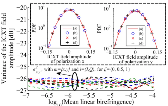
Thus, hXT i=σx,I2 +σ2x,Q+σ2y,I+σy,Q2 [12]. Fig. 2 shows σ2m,i for the two-core MCF and ζ = {0, 0.5, 1}, as a function of the mean linear birefringence, for a bending radius of 0.2 m. From Fig. 2, it is concluded that the variance of the ICXT field amplitude is similar for all polarization directions, I and Q components, mean linear birefringence and ζ, with discrepancy not exceeding 1 dB. It follows from these results that conditions (i) and (ii), introduced in section II, are valid, showing consistency for a wide range of mean linear birefringence. Similar conclusions were drawn for a 4-core MCF with a central core interfered by three outer cores. The PDFs of the I and Q components of the ICXT field amplitude of the two polarization directions are shown in Fig. 2 as insets, for ζ=1 and mean linear birefringence of 2×10⁻⁷. Those insets show that the PDFs of the I and Q components of the ICXT field amplitude of the two polarization directions are Gaussian distributed, as assumed in [7], [8], and that the DP-DCM provides estimates of the ICXT field amplitude in
−7 −6P5 −6 −5P5 −5 −4P5 −4 −27 −26 −25 −24 −23 −22 −21 −2F log 1FBMeanIlinearIbirefringence] VarianceIofItheIICXTIfield IamplitudeI[dB] σ2
m,i, withIm={x,y} andIi={I,Q}, forIζ={F,IFP5,I1}
−FP15 F FP15 1F−1 1FF 1F1 ICXTIfieldIamplitude PDF Ba]Bb] Bc] Bd] −FP15 F FP15 1F−1 1FF 1F1 ICXTIfieldIamplitude PDF Ba]Bb] Bc] Bd] ofIpolarizationIx ofIpolarizationIy
Fig. 2: Variance of the ICXT field amplitude, σm,i2 , as a function
of the base-10 logarithm of the mean linear birefringence, obtained by the CLMT. The PDFs of the I and Q components of the ICXT field amplitude of the two polarization directions, obtained through simulation, are shown as insets for ζ=1 and mean linear birefringence of 2×10⁻⁷. (a) I component (CLMT); (b) I component (DP-DCM); (c) Q component (CLMT); (d) Q component (DP-DCM).
good agreement with the CLMT. Similar conclusions were drawn for other bending radii, mean linear birefringences and ζ. It should be stressed that the DP-DCM proposed in this work allows evaluating the ICXT field amplitude of each polarization at the MCF output by using Eqs. (1), (2) and (7). In contrast, the analytical expressions reported in [7], [8] only allow to obtain the ICXT power. It was also observed that the in-phase and quadrature components of An,x(L) and
An,y(L), obtained with the CLMT, are Gaussian distributed
and uncorrelated, for different ζ, bending radii and mean linear birefringence. Thus, condition (iii) is validated.
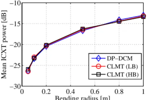
Fig. 3 shows the mean ICXT power as a function of the bending radius, for a two-core perfectly homogeneous MCF (nn = nm). The results of Fig. 3 show that the mean ICXT
powers obtained with the CLMT model for the LB and HB cases are similar, which agrees with the results of Fig. 2. More importantly, excellent agreement between the mean ICXT power estimates of the CLMT and DP-DCM is observed, with the discrepancy between the mean ICXT power estimates not exceeding 0.5 dB. This means that that the DP-DCM is applicable, in perfectly homogeneous MCFs, to a wide range of core birefringence and bending radii. Similar conclusions were also obtained for fiber twists of 0.01 and 0.05 turns/m.
Fig. 4 shows contours of the mean ICXT power, in decibel, for a two-core real homogeneous MCF [5], with nn= nm(1 + ∆n
(N ) nm). ∆n
(N )
nm is the normalized difference of
refractive indexes between the cores n and m, i.e. ∆n(N )nm =
(nn− nm)/nm. Very good agreement between the DP-DCM
(see Fig. 4(a)) and the CLMT (see Fig. 4(b)) occurs also for real homogeneous MCFs, with the discrepancy between the mean ICXT power obtained with the models not exceeding 0.6 dB. This small discrepancy is achieved for small variations of κnm along the longitudinal direction of propagation, z,
induced by fiber bending and twisting. Further investigation revealed that the discrepancy between the mean ICXT power estimates obtained from the DP-DCM and the CLMT can
0 0.2 0.4 0.6 0.8 1 −30 −25 −20 −15 −10 Bending radius [m]
Mean ICXT power [dB]
DP−DCM CLMT (LB) CLMT (HB)
Fig. 3: Mean ICXT power as a function of the bending radius, for homogeneous MCFs. Two cases of mean linear birefringence, 2×10⁻⁷ (LB) and 10−4 (HB), are considered, and ζ = 1.
0.01 0.05 0.1 0.15 −0.02 −0.01 0 0.01 0.02−32 −32 −32 −29 −29 −29 −26 −26 −26 −25 −25 −25 −24 −24 −24 −23 −23 −23 −22 −22 −22 −21 −21 −21 −20 −20 −18 −18 −16 Bending radius [m] ∆ n (N) nm [%]
(a) Obtained with the DP-DCM.
0.01 0.05 0.1 0.15 −0.02 −0.01 0 0.01 0.02 −32 −32 −32 −29 −29 −29 −26 −26 −26 −25 −25 −25 −24 −24 −24 −23 −23 −23 −22 −22 −22 −21 −21 −21 −20 −20 −18 −18 −16 Bending radius [m] ∆ n (N) nm [%]
(b) Obtained with the CLMT. Fig. 4: Contours of the mean ICXT power, in decibel, as a function of the normalized difference of refractive indexes between cores (∆n(N )nm), in percentage, and bending radius. A mean birefringence
of 2×10⁻⁷is considered and ζ = 1.
increase to 3-4 dB when the variation of κnm along z is
not negligible. In this case, the ICXT estimates of the DP-DCM are not accurate and generalization of the model to take into account the dependence of κnm on z is required.
This study is left for future work. It should be noted that the bending radii shown in Figs. 4(a) and 4(b) are smaller than the ones of Fig. 3 because the critical bending radius, Rth,
i.e. the maximum bending radius for which the DCM is valid, is smaller for larger |∆n(N )nm|, as Rth = Λnm/|∆n
(N ) nm| [3],
[5]. Thus, we have Rth = 0.15 m, for |∆n (N )
nm| = 0.02%
and Λnm = 30 µm. It was concluded that, if a 4-core MCF
with 3 interfering cores with small κnmvariations along z and
Rth= 0.25 m is considered, the discrepancy of mean ICXT
power estimates obtained with the CLMT and DP-DCM do not exceed 1 dB for bending radii not exceeding 0.21 m. For bending radii closer to Rth, the discrepancy may exceed 1 dB.
The results obtained with the CLMT model required solving numerically a system of differential equations with a small step. A maximum step of 10−4 m was considered in this paper, although it can be of the order of the wavelength if larger twisting rates are considered. In general, the number of steps is given by L/∆z, where ∆z is the step size. In comparison, the number of PMPs used in the DP-DCM, given by 2fTL, is much smaller. For example, with ∆z = 10−4 m,
fT = 0.1 turns/m and L = 200 m, 2×10⁷ steps are required.
The mean ICXT power estimates obtained with such a large number of steps may take several days to obtain. In contrast,
only 40 PMPs are used in the DP-DCM, under the same conditions, which allows for very fast estimates. Thus, the DP-DCM is much less computationally demanding, allowing for quick ICXT estimates without compromising accuracy.
IV. CONCLUSION
The DCM for ICXT estimation in weakly-coupled MCFs was generalized to a DP scheme and validated by comparison of the mean ICXT power and PDFs of the ICXT field amplitude estimates with the ones obtained with a more rigorous, yet much more computationally demanding, model based on the CLMT. Good agreement between the estimates of the mean ICXT power and of the PDFs of the ICXT field amplitude components of the polarization directions obtained from the DP-DCM and from the CLMT is observed for a small inter-core coupling coefficient variation along the MCF. The DP-DCM may be of particular interest for the performance analysis of MCF transmission systems employing direct-detection receivers, in which the time-varying photodetected ICXT results mainly from the beating between the ICXT field component of the interfering cores and the optical carrier field of the interfered core.
REFERENCES
[1] J. Sakaguchi, B. Puttnam, W. Klaus, Y. Awaji, N. Wada, A. Kanno, T. Kawanishi, K. Imamura, H. Inaba, K. Mukasa, R. Sugizaki, T. Kobayashi, and M. Watanabe, ”305 Tb/s space division multiplexed transmission using homogeneous 19-core fiber,” J. Lightw. Technol., vol. 31, no. 4, pp. 554-562, Feb. 2013.
[2] R. Lu´ıs, B. Puttnam , A. Cartaxo, W. Klaus, J. Mendinueta, Y. Awaji, N. Wada, T. Nakanishi, T. Hayashi, and T. Sasaki , ”Time and modulation frequency dependence of crosstalk in homogeneous multi-core fibers,” J. Lightw. Technol., vol. 34, no. 2, pp. 441-447, Jan. 2016.
[3] T. Hayashi, T. Taru, O. Shimakawa, T. Sasaki, and E. Sasaoka, ”Design and fabrication of ultra-low crosstalk and low-loss multi-core fiber,” Opt. Express, vol. 19, no. 17, pp. 16576-16592, 2011.
[4] A. Cartaxo, R. Lu´ıs, B. Puttnam, T. Hayashi, Y. Awaji, and N. Wada, ”Dispersion impact on the crosstalk amplitude response of homogeneous multi-core fibers,” Photon. Technol. Lett., vol. 28, no. 17, pp. 1858-1861, Sep. 2016.
[5] A. Cartaxo and T. Alves, ”Discrete changes model of inter-core crosstalk of real homogeneous multi-core fibers,” J. Lightw. Technol., vol. 35, no. 12, pp. 2398-2408, Jun. 2017.
[6] A. Macho, C. Garc´ıa-Meca, F. Fraile-Pel´aez, M. Morant, and R. Llorente, ”Birefringence effects in multi-core fiber: coupled local-mode theory,” Opt. Express, vol. 24, no. 19, pp. 21415-21434, Sep. 2016.
[7] M. Koshiba, K. Saitoh, K. Takenaga, and S. Matsuo, ”Analytical ex-pression of average power-coupling coefficients for estimating intercore crosstalk in multicore fibers,” Photonics Journal, vol. 4, no. 5, pp. 1987-1995, Sept. 2012.
[8] T. Hayashi, T. Sasaki, E. Sasaoka, K. Saitoh, and M. Koshiba, ”Physical interpretation of intercore crosstalk in multicore fiber: effects of mac-robend, structure fluctuation, and micmac-robend,” Opt. Express, vol. 21, no. 5, pp. 5401-5412, Mar. 2013.
[9] T. Alves, R. Lu´ıs, B. Puttnam, A. Cartaxo, Y. Awaji, and N. Wada, ”Performance of adaptive DD-OFDM multicore fiber links and its relation with intercore crosstalk,” Opt. Express, accepted for publication, 2017. [10] G. Agrawal, ”Nonlinear fiber optics,” third edition, Academic Press,
chapter 6, pp. 239-240.
[11] P. Wai, C. Menyuk, and H. Chen, ”Stability of solitons in randomly varying birefringent fibers,” Opt. Lett., vol. 16, no. 16, pp. 1231-1233, 1991.
[12] T. Hayashi, T. Taru, O. Shimakawa, T. Sasaki, and E. Sasaoka ”Charac-terization of crosstalk in ultra-low-crosstalk multi-core fiber,” J. Lightw. Technol., vol. 30, no. 4, Feb. 2012.