Miloš Slankamenac, Milan Nikolić, Kalman Babković, Goran Stojanović, Ivan Mezei, Mirjana Damjanović
AN EDUCATIONAL MULTI – USER MEASUREMENT
SYSTEM (EMUMS)
The goal of the project educational multi-user measurement system (emums) has been to produce specification, design and implementation of an educational measuring system that is used for measurement of non-electrical values, such as temperature, pressure, fluid movement, etc. In this paper we present overview of the project. We also present some design and implementation details, the features of the final product and experience with students.
1. Introduction
EMUMS is a measurement system that is used for learning pupils at Technical Secondary Schools and students at Technical Universities. The goals of learning students on EMUMS are: to help students to visualize the functionality of technical processes and measurement techniques of non-electrical values, such as temperat-ure, presstemperat-ure, fluid movement, humidity of fluid, frequency of motor rotation, etc., enable students ease understanding of the measurement system, its design and the functioning of some parts of industrial systems, to help students accept the knowledge about methods and techniques of automatic control systems. The ad-vantage of this approach is simple and quite cheap implementation solution be-cause EMUMS consists of one device for acquisition data from the process, which sends data to nine emulators at most and every student gets data at the same time, [1]. Using the EMUMS, teacher has the possibility of observing what students are doing on his/her monitor
ANALELE UNIVERSITĂŢII
“EFTIMIE MURGU” REŞIŢA
should be compatible, meaning that it must have the possibility for direct link over standard signals and connectors. The EMUMS system is implemented by means of micro controllers, programmable logic circuits and appropriate Windows/Dos based software support.
2. Implementation
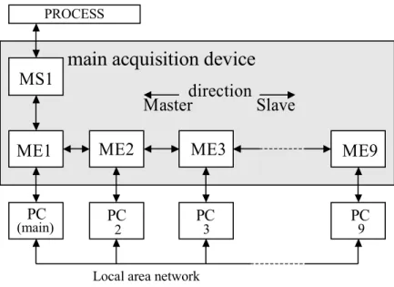
Figure 1 depicts the EMUMS that consists of main acquisition device – master (MS1) and nine measurement emulators at most.
PROCESS
MS1
PC
(main) 2 3 9
Local area network
main acquisition device
direction
Master
Slave
ME1
ME2
ME3
ME9
PC
PC
PC
Figure 1. Multi – user measurement system for educational purposes (EMUMS
)
3. Technical characteristics and overview of MS1
Main acquisition device MS1 converts input measurement signals to their digital form and sends them to measurement emulators by means of serial communication. Figure 2 represents a block diagram of the main acquisition device. Main acquisition unit is designed around Atmel AT89C52 microcontroller [2]. There are eight analog inputs that measure current or voltage, depending on what input connectors are used. Measuring range of current input is 0-20 mA, meaning that it is used for connection with a standard current sensor that have working voltages lower than 24V. The maximum value of current is limited to 26 mА. Voltage inputs measure the voltage that is supplied from adequate connector. This device can be configured to measure voltage in range of 0 - 10V or –10 - 10V. Pulse inputs enable connection with device that generates pulse signal. On the connector for these inputs, the voltage is set to 24V, which provides the power supply of device that generate pulse signal. The counter of pulses is sensitive to signal edges (changing signal from low to high level and vice versa) that are supplied to counter. Pulse inputs have protection from reverse voltage that is brought between input connections. This voltage should not exceed 24V.
Microcontroller convertor Serial communication Voltage or current segment 1 Voltage or current segment 2 Voltage or current segment 8 Pulse input segment Voltage or current signal Voltage or current signal Voltage or current signal Pulse signal . . . .
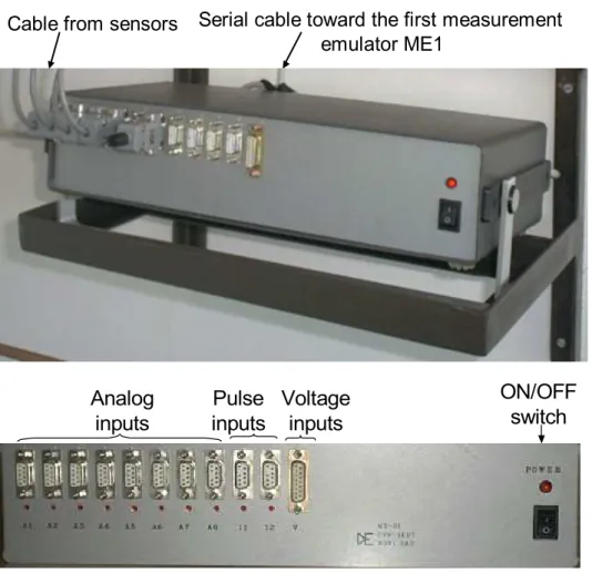
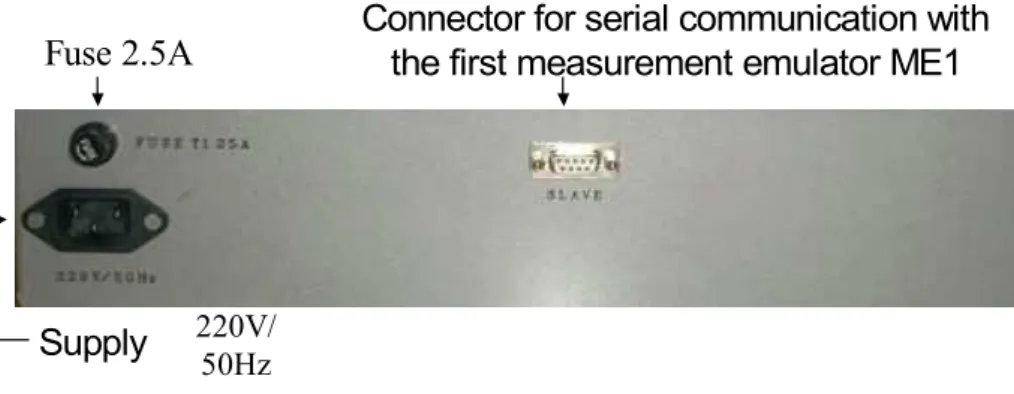
Figure 3 shows main acquisition device, front and back panel. The device is mounted on wall and connected with emulators. Signals from sensors are provided on front panel connectors. Front panel contains eight SUB D-9 connectors used as analog inputs, two as pulse inputs and one SUB D-25 as voltage inputs. Power led and switch on front panel, power supply cable and fuse on back panel supplies device with power. On back panel one SUB D-9 connector is mounted for connection with first emulator.
Cable from sensors
Serial cable toward the first measurement
emulator ME1
Analog
inputs
Voltage
inputs
Pulse
inputs
Fuse 2.5A
220V/ 50Hz
Connector for serial communication with
the first measurement emulator ME1
Supply
Figure 3. Appearance of the main acquisition device
4. Technical characteristics and overview of measurement emulator ME
PC receives data from a measurement emulator. Measurement emulators receive acquired data from MS1 via serial communication RS422, and then via parallel printer port of PC computer. ME1 provides computer and user’s program with measuring data. Combination of a measurement emulator and a parallel printer port of PC is similar to a complex measurement device designed for PC (both approaches use data and command registers for communication). Measurement emulators use three LEDs that indicate the configuration of the whole EMUMS and internal diagnostic and configuration. Applied method of automatic addressing provides simple servicing of measurement emulators or change of number of used MEs without any user intervention. Figure 4 shows block diagram of a measurement emulator.
Serial link in MS1
direction
Supply
220V≈/5VSerial
communication
segment
Serial link in ME
direction
Communication
microcontroller
Serial communication segment provides link to ME1 on one side and MS1 on the other. Link toward MS1 is master direction, and link toward ME is slave direction. Principal of communication with PC computer via parallel port is called handshaking. For this purpose, appropriate hardware is used, that provides synchronized set of signals.
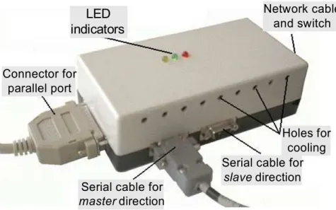
For indication of working process there are three LED indicators:
• Green LED – indication that ME is turned on and it has power supply
• Red LED – if it blinks with a period of 1 second, ME will be in initial phase, meaning it is not addressed. When properly configured, red LED is always on.
• Yellow LED – It blinks with a period of 1s, if identification is turned on ME using software for configuration system EMUMS. It is always on, if ME is configured to control analog and digital outputs. Otherwise this LED is off.
These LED indicators are showed on figure 5.
LED
indicators
Network cable and switch
Connector for parallel port
Serial cable for
master direction
Serial cable for
slave direction
Holes for cooling
Figure 5. Measurement emulator
5. Communication between MS1 and ME
communication. Using addressing MS1 knows which ME responded. All ME have unique addresses that are determined automatically. Input signals can be allocated to any number of measurement emulators. In this way, measurement of various values on different PC is possible, and because of that, this system is multi-user. For example, one student measures temperature on a PC, another measure pressure only, or fluid movement or any combination.
6. Configuration software
The configuration software is a part of measurement system. Software can be executed and accessed only from the teacher’s computer to which ME1 is connected. It is used for configuring the system, especially MS1. The configuration software is developed in two versions, DOS and Windows 95/98. The EMUMS saves last configuration set even after it is turned off, thus the configuration software is used only when configuration changes are to be done.
The adjustable parameters:
• Measurement range of the analog inputs, current 0(4)-20 mA and voltage 0-10 V or +/-10 V
• Two separate pulse inputs can be used in five configuration: two separate inputs, one input measure the direction while other measure speed, or as a quadrature input of incremental encoder in three possible resolutions. Besides, the measurement of position instead of speed is possible.
• The enable/disable and mapping of analog inputs on particular MEs.
• Locating MEs according to their address.
Configuration of the system should be done when associated sensors are changed. If mapping is not the same on all MEs, remapping inputs will be necessary when some ME is not in communication chain.
7. Conclusion
EMUMS has been used in teaching Measurement techniques at Mechanic Secondary School in Novi Sad. Two years of hands-on experience, and exam test results show that EMUMS is a good starting tool in teaching measurement and control fundamentals. Significant pupil approval and better test results were achieved compared with the results of pupils that did not use EMUMS in the lab exercises.
References
[1] Multi-user measurement system for electric power applications, M. Nikolić, K. Babković, I. Mezei, G. Stojanović, M. Slankamenac, M. Damnjanović, (in Serbian), Proc. Congress of Metrologists, Belgrade, Serbia and Montenegro, May 2003.
[2] Atmel Products CD Data Book, February 2000 [3] Texas Instruments, Data Acquisition Circuits, 1998.
Address: