i
Faculty of Engineering of University of Porto
Development of a Stimulator for Neuromuscular
Blockage Assessment
Carla Patrícia Nunes da Mota
iii
Faculty of Engineering of University of Porto
Development of a Stimulator for Neuromuscular
Blockage Assessment
Carla Patrícia Nunes da Mota
Dissertation developed in the context of the Integrated Master in
Bioengineering
Biomedical Engineering Branch
Supervisor: Joaquim Gabriel Magalhães Mendes (Prof.)
Co-supervisor: Rui Pedro Correia (MSc.)
iv
i
Resumo
Nos procedimentos cirúrgicos, as drogas de bloqueio neuromuscular são usadas para facilitar a intubação traqueal, proporcionar relaxamento muscular e imobilidade, e auxiliar a ventilação mecânica. Além disso, o anestesista deve assegurar-se que o paciente saia da sala de operações com a força muscular recuperada, especificamente nos músculos respiratórios e nas vias aéreas superiores, de modo a manter uma respiração autónoma. Para atingir este objetivo, duas estratégias podem ser adotadas: titular os agentes bloqueadores neuromusculares de modo a que nenhum efeito residual permaneça no final da cirurgia, ou pela administração de uma droga de ação inversa, que acelera a recuperação do paciente. Em ambos os casos deve ser efetuada uma monitorização cuidadosa para garantir uma avaliação correta da extensão do bloqueio neuromuscular. Entre os diferentes tipos de monitorização, o mais preciso baseia-se na avaliação quantitativa e objetiva das respostas evocadas mecanicamente, desencadeadas pela estimulação elétrica fornecida por um estimulador de nervos periféricos. Para o efeito, são aplicados padrões de estimulação e as respetivas respostas são registadas e avaliadas.
Mesmo não sendo habitualmente efetuado, monitorizar os efeitos das drogas de bloqueio neuromuscular precisa ser realizado rotineiramente. Está comprovado que a monitorização neuromuscular pode auxiliar no diagnóstico de relaxamento esquelético inadequado durante a cirurgia e recuperação insuficiente após a cirurgia. Além disso, pode reduzir a incidência de complicações na unidade de recuperação pós-anestésica causada pelo fenómeno da curarização residual pós-operatória. Esse bloqueio residual é de grande preocupação clínica, pois aumenta o risco de complicações pulmonares, levando a um aumento da morbidade e mortalidade.
Este projeto faz parte de uma abordagem inovadora de desenvolvimento de um estimulador capaz de fornecer informação mais segura e fiável do bloqueio neuromuscular, através da criação de padrões de estimulação personalizados, permitindo um bloqueio neuromuscular individualizado e mais adequado durante os procedimentos médicos. Para tal, foi desenvolvido um circuito eletrónico e uma interface feita em LabVIEW. A interface permite ao utilizador programar o sistema eletrónico de modo a obter-se um estímulo com os atributos pretendidos. O sistema corretamente transmite um sinal com corrente controlável e com as características de onda desejadas. A tensão do estímulo necessária para uma estimulação apropriada seria conseguida a partir do uso de uma fonte de corrente adequada.
Palavras-chave: bloqueio neuromuscular, estimulador de nervo periférico, resposta evocada,
ii
iii
Abstract
In surgical procedures, neuromuscular blocking drugs are used to facilitate tracheal intubation, to provide muscle relaxation and immobility, and to help mechanical ventilation. Furthermore, the anaesthetist should ensure that the patient leaves the operating room with unimpaired muscle strength, specifically respiratory and upper airway muscles recovery, in order to restore autonomous patient’s breathing. To achieve this goal, two strategies can be adopted: to titrate neuromuscular blocking agents so that no residual effect remains at the end of surgery or by administration of a reversal drug, accelerating recovery. In both cases, a precise monitoring should be undertaken to guarantee a correct assessment of neuromuscular blockade extent. Among different types of monitoring, the most accurate relies on a quantitative and objective evaluation of the mechanically evoked responses triggered by electrical stimulation, delivered from a peripheral nerve stimulator. For that, few stimulation patterns are applied and the mechanically evoked responses are recorded and evaluated.
Even though not consistently done, monitoring the effects of the neuromuscular blocking drugs need to be routinely performed. It is proved that neuromuscular monitoring can help in the diagnosis of inadequate skeletal relaxation during surgery and insufficient recovery after surgery. Also, it can reduce the incidence of complications in the post anaesthesia care unit caused by post-operative residual curarization phenomenon. This residual blockade is of great clinical concern since rises the risk of pulmonary complications leading to an increase in morbidity and mortality.
This project is an innovative approach of a stimulator able to provide a safer and more reliable evaluation of neuromuscular blockade by stimulating patients according to individual responses, allowing a personalized and more adequate neuromuscular blockade during medical procedures. For this purpose, it was created an electronic circuit and an interface developed in LabVIEW. The interface allows the user to programme the electronic system in order to obtain output stimulus with the intended attributes. The system successfully outputs a signal with controllable electric current, and with the chosen waveform characteristics. A correct voltage required for an appropriate stimulation could be achieved using a customized current source.
Keywords: Neuromuscular blockade, peripheral nerve stimulator, evoked response,
iv
v
Acknowledgements
First of all, I would like to thank to my closest family for all the support they gave me, and for being the reason why I love my life. I would also like to thank the help provided by my supervisor and co-supervisor, and Rui Fernandes from the electronics department for technical assistance.
Of course I would never forget to mention how amazing my friends are and how it is so important to me their friendship, love, and all the stupid conversations we constantly have, but most of all, how good they make me feel for letting me belong to their lives.
Last but not least, thank you Led Zeppelin, Pink Floyd and people that upload Jazz & Bossa Nova playlists on Youtube for feeding my ears while I was working.
vi
vii
Contents
Resumo ... i
Abstract ... iii
Acknowledgements ... v
Contents ... vii
List of figures ... ix
List of tables ... xi
Abbreviations ... xiii
Chapter 1: Introduction ... 1
1.1 - Background: Neuromuscular Transmission ... 1
1.2 - Mechanism of Action of Neuromuscular Blocking Drugs ... 3
1.3 - Nerve Stimulation ... 4
1.4 - Assessment of Stimulatory Response ... 11
1.5 - Stimulator devices ... 13
Chapter 2: Proposed device ... 17
2.1 – Electronic circuit ... 19 2.1.1 - Voltage regulator ... 19 2.1.2 - Current source ... 20 2.1.3 - Digital potentiometer ... 21 2.1.4 - Digital switch ... 22 2.2 - Practical considerations ... 23 2.2.1 - Test equipments ... 23 2.2.2 - Voltage regulator ... 23 2.2.3 - Digital potentiometer ... 24 2.2.4 - Current source ... 24
Chapter 3: Software development ... 27
3.1 – LabVIEW interface ... 27
3.2 – Arduino programming... 39
viii
Chapter 5: Conclusions ... 53
References ... 55
Annexes ... 59
ix
List of figures
Figure 1.1 - Physiology of neuromuscular transmission. (a) At the NMJ, where calcium influx
causes release of ACh. ACh then binds to the postsynaptic nAChR at the motor endplate. (b) Binding of two ACh molecules opens up the ion channel leading to an
action potential, which causes muscle contraction.. ... 2
Figure 1.2 - Single twitch pattern... 6
Figure 1.3 - TOF pattern... ... 7
Figure 1.4 - DBS 3-3 pattern... ... 7
Figure 1.5 - DBS 2-3 pattern... ... 8
Figure 1.6 - DBS 3-2 pattern... ... 8
Figure 1.7 - Tetanus pattern... ... 9
Figure 1.8 - PTC pattern... ... 9
Figure 1.9 - TOF-Watch monitor. (1) Stimulating electrodes applied over ulnar nerve; (2) accelerometer taped to thumb; (3) display screen... ... 14
Figure 1.10 - Datex–Ohmeda M-NMT neuromuscular transmission module with kinemyographic mechanosensor. (1) Stimulating electrodes applied over ulnar nerve; (2) piezoelectric mechanosensor.... ... 15
Figure 2.1 - Diagram of the developed system... ... 18
Figure 2.2 - Functional diagram of the LT3092 as a current source... ... 20
Figure 2.3 - Potentiometer's behaviour as a rheostat.... ... 21
Figure 2.4 - Functional diagram of the AD5241... 22
Figure 2.5 - Functional diagram of the TS12A44513.... ... 23
Figure 2.6 - Circuit of the TS12A44513... ... 23
Figure 2.7 - Eagle schematic of the voltage regulator circuit... ... 24
x
Figure 2.9 - Output current using load resistances of 1,2 kΩ and 3,3 kΩ.... ... 25
Figure 3.1 - User interface... ... 28
Figure 3.2 - General diagram of interface functioning... 29
Figure 3.3 - User interface. The chosen stimulus pattern is Single twitch... ... 30
Figure 3.4 - User interface. After selecting the stimulation pattern, the corresponding parameters can be adapted... ... 31
Figure 3.5 - User interface. When pressed the “Confirm settings” button, the “Start stimulation” button becomes enabled... ... 32
Figure 3.6 - User interface. When the stimulation starts, the LED placed in the selected stimulation button is turned on... ... 33
Figure 3.7 - User interface. Since the previous selected pattern was Single twitch, other pattern can interrupt the transmission of the stimulus, e.g. Tetanus... ... 34
Figure 3.8 - User interface. While a Tetanus stimulus is transmitted, the remaining stimulation pattern buttons are disabled. The same happens for PTC, DBS 3:3, DBS 2:3 and DBS 3:2... ... 35
Figure 3.9 - Structure of the message sent from LabVIEW to Arduino... ... 36
Figure 3.10 - Scheme of the Arduino code structure.... ... 40
Figure 4.1 - Electronic circuit.... ... 43
Figure 4.2 - Eagle schematic of the electronic circuit.... ... 44
Figure 4.3 - Single twitch signal.... ... 45
Figure 4.4 - TOF signal... ... 46
Figure 4.5 - Measurement of the temporal distance between two TOFs.... ... 46
Figure 4.6 - Tetanus signal.... ... 47
Figure 4.7 - Measurement of the tetanus stimulus duration.... ... 47
Figure 4.8 - PTC signal.... ... 48
Figure 4.9 - DBS 3-3 signal.... ... 49
Figure 4.10 - Measurement of the temporal distance between the first and second bursts in the DBS 3-3 signal... ... 49
Figure 4.11 - DBS 2-3 signal.... ... 50
Figure 4.12 - Measurement of the temporal distance between the first and second bursts in the DBS 2-3.... ... 50
Figure 4.13 - DBS 3-2 signal.... ... 51
Figure 4.14 - Measurement of the temporal distance between the first and second bursts in the DBS 3-2 signal.... ... 51
xi
List of tables
Table 2.1 — Device specifications. ... 17
Table 2.2 — Expected and measured resistance values. ... 24
Table 3.1 — Setting parameters and corresponding options... 37
Table 3.2 — Serial communication settings... 39
xii
xiii
Abbreviations
ACh Acetylcholine
AChE Acetylcholinesterase DBS Double-burst stimulation EMI Electromagnetic interference nAChR Nicotinic acetylcholine receptor NMB Neuromuscular blockade
NMBA Neuromuscular Blocking Agent NMBD Neuromuscular Blocking Drug NMJ Neuromuscular junction
OR Operating room
PORC Post-operative residual curarization PTC Post-tetanic twitch count
xiv
1
Chapter 1: Introduction
1.1 - Background: Neuromuscular Transmission
The central nervous system is the part of the nervous system that comprises the brain and the spinal cord. Its primary component is the neuron, or nerve cell. A neuron is an electrically excitable cell able to be stimulated and to transmit information through electrical and chemical signals by conducting impulses. The typical structure of a neurons consists of a cell body, dendrites and an axon. Impulses are carried along one or more dendrites to the cell body and is the axon that carries the impulse away from the cell body. It is in the synapse that a neuron communicates electrical or chemically with another neuron or target efferent cell through a phenomenon called neuromuscular transmission [1].
Motor neurons are nerve cells that are responsible for transmitting signals from the spinal cord to an effector (muscle or glandular) tissue [2]. They innervate the body muscles and thus are involved in all voluntary and involuntary movements such as speaking, walking, breathing and swallowing [3]. Motor neuron cell bodies lie in the anterior horn of the spinal cord or in the corresponding motor nuclei of cranial nerves, and axons are projected to or outside of the spinal cord. Somatic motor neurons are motor neurons originated in the central nervous system whose axons are projected to skeletal muscles, enabling its contraction [2].
Skeletal muscle fibres are fast conducting fibres since are innervated by somatic motor neurons – generally myelinated – which provides better insulation and more rapid conduction of impulses.
A motor unit comprises all muscle fibres that are innervated by a single motor neuron and the motor neuron itself. Each individual motor neuron innervates several muscle fibres by its axonal terminals. It is the neuromuscular junction (NMJ) the specialized synapse that connects the motor neuron with the target skeletal muscle fibre [4].
The anatomy of the NMJ consists of a prejunctional motor nerve ending – presynaptic region – separated from the highly folded postjunctional membrane of the skeletal muscle – motor endplate – by a synaptic cleft. In the pre and postjunctional sites are located the nicotinic acetylcholine receptors (nAChRs). The nAChR has a rosette shape made up of five subunits (2-α, 1-β, 1-ɣ and 1-δ) arranged such that a channel is formed, and allows the flow of ions along a concentration gradient across cell membranes – the basis of normal neuromuscular transmission [5].
The neuromuscular transmission is initiated by arrival of an impulse at the motor nerve terminal. In the motor nerve terminal is synthesized, stored in vesicles and released the neurotransmitter molecules – acetylcholine (ACh). Vesicles spontaneously empty into the synaptic gap. However, this spontaneous release is not sufficient to trigger muscle contraction,
2
until the arrival of action potentials at the motor neuron. In this case, an influx of Ca2+ is
triggered into the nerve ending and several hundred vesicles synchronously release their ACh into the synaptic cleft. If ACh binds to both of the nAChR α-subunits on postjunctional membranes, the nAChR ion channel opens, allowing the passage of Na+ and Ca2+ into and K+
ions out of the muscle cell. This change in permeability due to ionic changes causes a decrease in the transmembrane potential from about -90mV to -45mV, at which point a propagated action potential spreads over the surfaces of skeletal muscle fibres and leads to muscular contraction. To prevent sustained depolarization, the membrane permeability is restored (repolarization) by the action of the enzyme acetylcholinesterase (AChE) which rapidly hydrolyses ACh.
The mechanism of neuromuscular transmission is represented in Figure 1.1.
Figure 1.1 - Physiology of neuromuscular transmission. (a) At the NMJ, where calcium influx causes
release of ACh. ACh then binds to the postsynaptic nAChR at the motor endplate. (b) Binding of two ACh olecules opens up the ion channel leading to an action potential, which causes muscle contraction [6].
One of the primary anaesthetic goals for the intraoperative management of surgical patients is akinesia (loss of ability to move muscles voluntarily). When patients are pharmacologically unable to move, surgical exposure is improved. There are a number of medications and combinations of medications that can cause akinesia. The most common drugs used in the operating room are the muscle relaxants or neuromuscular blockers.
3
1.2 - Mechanism of Action of Neuromuscular Blocking Drugs
Neuromuscular blockers induce a state of pharmacologic paralysis by interfering with the normal processes of neurotransmitter–receptor interaction at the NMJ [6]. There are two main types of neuromuscular blockers: depolarizing and nondepolarizing.
1.3.1 - Depolarizing neuromuscular blocking agents
Depolarizing NMBDs mimic the effect of ACh and therefore can be considered agonists, although they block neurotransmission after an initial stimulation [7]. In fact, the only depolarizing NMBD clinically used – succinylcholine – is composed by two ACh molecules bounded together. Succinylcholine molecule binds to the two α-subunits of a nAChR, and depolarization occurs, inducing the same effect as ACh at the nAChR. When succinylcholine binds to nAChR, the voltage-sensitive sodium channels sense membrane depolarization and open, passing the current. It leads to endplate depolarization. The channels thereafter close and remain inactivated [8]. To reactivate these channels, the membrane potential must be reset. The response to ACh takes only milliseconds due to its rapid hydrolysis by AChE within the synaptic cleft, reverting the endplate to its resting state. However, succinylcholine is not metabolised by the AChE, so the ACh receptors activation is prolonged [8]. Depolarizing NMBDs are not removed from the synaptic cleft until they are eliminated from the plasma, being the duration of block determined by the time required to clear them from the body. Since depolarizing NMBDs cause continuous depolarization of the endplate, a quick change from excitation and muscle contraction to block of transmission is observed.
1.3.2 - Non-depolarizing neuromuscular blocking agents
Non-depolarizing NMBDs antagonize the action of ACh by competitively preventing the binding of ACh to the postsynaptic nAChR. Unlike depolarizing NMBDs, non-depolarizing NMBDs do not produce conformational changes in the receptor [8]. If a single molecule of non-depolarizing NMBD binds to one α-subunit of a nAChR, the voltage-sensitive sodium channel cannot open, preventing the depolarization of the channel [7]. The binding of antagonists to the receptors is dynamic, that is, if the concentration of ACh is increased, it has a higher chance of occupying the two α-subunits of the receptors rather than the antagonist. With non-depolarizing NMBD, there is a gradual reduction in endplate potential until it is below the threshold to trigger a propagation action potential to produce muscle contraction. Neuromuscular blockade (NMB) only becomes evident when 70-80% of receptors are occupied by non-depolarizing NMBD molecules [8]. To achieve a complete NMB, at least 92% of receptors must be occupied. Non-depolarizing NMBDs - Pancuronim, Vecuronium, Rocuronium, Atracurium, Cisatracurium and Mivacurium – are clinically chosen according to factors such as the difference in onset, duration of action, rate of recovery, metabolism and clearance [9] [10].
An adequate recovery from NMB is crucial to restore motor laryngeal reflexes, respiratory response and motor function [10][11].
However, patients receiving NMBDs may be at risk of postoperative residual curarization (PORC). This residual blockade related phenomenon is of great clinical concern and might occur due to an excessive neuromuscular blocking drugs dosage, early administration of reversal
4
drugs, or abnormal response of the patient. PORC is associated to impairment of the respiratory response, and dysfunction of the pharynx and upper oesophagus resulting in an increased risk of postoperative pulmonary complications, and consequently an increased postoperative morbidity and mortality.
There are several ways to reduce the risk of developing residual blockade when using NMBDs. One approach is to wait for spontaneous recovery by diffusion of NMBDs away from NMJ, combined with clinical evaluation of neuromuscular function recovery. Other method is the acceleration of recovery through a systematic pharmacologic reversal of the NMB by use of reversal agents [10][12].
1.3.3 - Neuromuscular blockade reversal agents
Non-depolarizing NMB is reversed by using cholinesterase inhibitors. These agents act indirectly by inactivating the AChE in the synaptic cleft of NMJ, increasing the competitive position of ACh [11]. This position is majorly influenced by two factors: the concentration of ACh and the period of time ACh remains in the cleft. Increasing the number of ACh molecules in the synaptic cleft raises the probability of ACh to occupy the recognition sites of the receptor, restoring NMJ transmission. It also enables unoccupied receptors to become occupied with ACh because only about 500,000 of 5 million existing receptors are activated by a single nerve impulse, remaining a considerable number of unused receptors. The second factor, length of time ACh remains in the cleft, is essential because prolonging the time during which ACh is in the synaptic junction allows ACh to more effectively bind to the receptor after the non-depolarizing NMBA dissociate from it. That is, the AChE acts so quickly on ACh that most of molecules are destroyed before any substantial amount of non-depolarizing neuromuscular blocking agents (NMBAs) have dissociated from the receptors so that ACh molecules can bind to them [7].
Since depolarizing NMBAs are eliminated from the NMJ by diffusion, reversal agents do not exert any effect on the NMB provoked by these drugs [6]. Sugammadex, Neostigmine and Edrophonium are the most clinically used AChE inhibitors, which reversibly attach to AChEs [13].
The most reliable method to monitor the pharmacologic effects of NMBDs is by evaluation of the mechanically evoked responses produced by electrical stimulation delivered from a peripheral nerve stimulator [9].
1.3 - Nerve Stimulation
The clinical basis of nerve stimulation involves applying an electrical stimulus directly over a motor nerve and monitoring the associated response. This motor response can be used to determine the degree of NMB, to judge spontaneous recovery from an NMBD-induced blockade, to ensure ideal intubating conditions, to maintain adequate paralysis during critical operative periods, and to monitor the return of function so that extubating criteria can be met [6][9].
5 1.4.1 – Physiological Principles of Nerve Stimulation
Neuromuscular function, influenced by the effects of NMBAs, is monitored by assessing the mechanically evoked responses of the muscle to a supramaximal stimulation (i.e. one in which all axons in the nerve are made to discharge) [14]. The stimulation of a muscle fibre obeys to the all-or-none law which states that a muscle fibre responses to a stimulus when it exceeds the threshold potential. However, when the whole muscle is stimulated, the response is determined by the number of muscle fibres stimulated. That is, if the nerve is stimulated with an appropriate intensity, all the muscle fibres, innervated by that nerve, contract and a maximal response is generated [15].
After the administration of NMBDs, the response of muscles decreases attending to the number of nerve fibres blocked. When a continuous stimulation is applied, the degree of reduction in response discloses the extent of NMB.
To monitor the effects of NMBDs, mechanically evoked responses are assessed, being obtained after the application of patterns of nerve stimulation.
1.4.2 - Patterns of Nerve Stimulation
For evaluation of neuromuscular function the most commonly used patterns of electrical nerve stimulation are Single twitch, Train-of-four, Tetanic, Post-tetanic count and Double burst stimulation.
a) Single Twitch
The Single twitch is a single supramaximal electrical stimulus applied to the target motor nerve; the subsequent motor response is evaluated. The frequency range with which single stimulus is applied is 0.1-1 Hz. The fatigue of muscle response – fade – can be observed after high-frequency stimulation (higher than 0.15 Hz). The fade phenomenon occurring in non-depolarizing NMB is due to the inhibition of presynaptic ACh release [16]. The higher the stimulation frequency is, the more pronounced is the fade, overemphasizing NMB. Therefore, the most common frequency applied is 0.1 Hz [3]. The ratio of the evoked response and the response before muscle relaxation – T1% - gives an indication of the NMB extent [17]. In both depolarizing and non-depolarizing NMBs there is a progressive decay in twitch height. This stimulation mode only presents clinical relevance when used as a component of TOF or PTC.
6
b) Train-of-four stimulation
The Train-of-four stimulation (TOF) is based on the concept that ACh is depleted by successive stimulations. This method relies on four electrical stimuli given at a frequency of 2Hz. These four twitches are sufficient because following stimulation fails to promote the release of additional ACh. Repeated TOF stimulation can lead to a progressive fade of the motor response, existing or not muscle blockade (i.e. 2Hz is above the threshold of 0.15 Hz, as previously explained in Single twitch method). To avoid this phenomenon from happening and falsifying the analysis of the NMB, an interval between two TOF series must be established to allow the regeneration of the neuromuscular endplate. The optimal interval between two successive TOF series is 10-20s [9].
The degree of fade, or TOF ratio, indicates the extent of the NMB and is given by the quotient of the amplitude of the fourth response (T4) and the amplitude of the first response (T1) [18].
Once applied TOF stimulation in an unrelaxed patient, all four responses are detected and have the same intensity (TOF ratio equal to 1) [3].
As the administration of non-depolarizing NMBDs takes effect on the NMJ, is produced a decrease in magnitude of the first twitch compared with a pre-relaxant stimulus. Also, all four stimulatory responses exhibit fade (due to muscle fatigue) starting with the fourth twitch until no responses are detected [9]. The degree of receptor occupancy is indicated by the number of provoked twitches, making it easier to set the proper time for intubation. The loss of T4, T3, T2 and T1 responses corresponds to 75%, 80%, 90% and 100% receptors occupancy, respectively. During recovery of neuromuscular function, twitches appear in the reverse order [17].
Intraoperatively, the extent of NMB can be accessed by counting the detectable responses after TOF stimulation – TOF count. If one or two of the four responses are detectable, the degree of relaxation will be acceptable for the majority of surgical procedures. As the depth of NMB is related with the TOF count, the reappearance of responses is an indicator to evaluate the time point for NMBD reinjection. Nonetheless, TOF count allows to infer whether the spontaneous recovery from NMB is sufficient to reverse the residual blockade with reversal drugs. The recovery begins as soon as all the four responses become discernible again [3].
Since depolarizing drugs have a different acting mode in NMB, there is no fade in response to TOF stimulation (TOF ratio equal to 1), and all four responses are equally reduced. Moreover,
0,2 ms
1 s
7 all TOF responses vanish at the same time, meaning that TOF count is equal to zero or four. In this way, TOF is not suitable for describing a depolarization blockade [16].
Figure 1.3 contains a representation of the TOF pattern at a frequency of 1 Hz.
c) Double-burst stimulation
The Double burst stimulation (DBS) consists of two short bursts of three stimulus (DBS 3-3), or one burst of two stimulus followed by one of three stimulus (DBS 2-3), or one burst of three stimulus followed by one of two stimulus (DBS 3-2), both bursts at 50 Hz, separated by 750 ms [9][17]. When DBS is applied to the unblocked NMJ, this stimulation pattern induces two short muscle contractions. In a patient with a non-depolarizing NMB, DBS induces a weaker second response. A good correlation between the ratio of second burst to first burst and TOF ratio has been reported [19]. Moreover, has been demonstrated that DBS is more sensitive than TOF in the manual detection of residual NMB. That is, manual detection of fade is improved with DBS stimulation when TOF ratio is less than 0.4. However, for a TOF ratio greater than 0.7 it is not ensured that a manual assessment of DBS allows a reliable detection of fade [20]. For monitoring depolarizing blockade, DBS offers no advantages over TOF [3].
Figures 1.4, 1.5 and 1.6 displays a representation of DBS 3-3, DBS 2-3 and DBS 3-2 patterns, respectively, all three at 50 Hz.
0,2 ms
1 s
0,2 ms
20 ms 750 ms
Figure 1.3 – TOF pattern.
8
d) Tetanic stimulation
The Tetanic stimulation is accomplished by applying an intense stimulus for 5 s at 50-120 Hz to promote the release of ACh at the NMJ. The result is a detectable fade in muscle contraction whose extent is related to the NMB extent [17]. In the presence of non-depolarizing NMBDs at the NMJ, the response to tetanus fades [9]. The higher the frequency of tetanic stimulation, the more evident is the fade [3]. High frequency stimulation of the motor nerve produces a great discharge of ACh in the synaptic cleft. This leads to a decrease in ACh release until the equilibrium between mobilization and synthesis is reached. To produce a full muscular response in a normal muscular contraction, the nerve is stimulated with a high frequency stimulus for a higher release of ACh above the necessary (margin of safety). However, in the presence of non-depolarizing NMB, the number of available nAChR is reduced. This reduces the margin of safety of neuromuscular transmission, decreasing the force of muscle contraction – fade [21]. At the end of tetanus, another reaction occurs – post-tetanic facilitation – characterized by a transient excessive release of ACh at the NMJ. The effect of this phenomenon depends on the duration and intensity of the stimulus. It can last 3-5 minutes after a 5 s stimulation at 50 Hz. Therefore, to avoid an overestimation of the extent of neuromuscular recovery, the monitoring is not recommended during this period.
Tetanic stimulation is painful, and the higher the stimulation frequency is, the more the patient feels pain. For that reason, this stimulation mode may only be employed on anesthetized patients. For current clinical applications, tetanic stimulation is not as relevant
0,2 ms 20 ms 750 ms 0,2 ms 20 ms 750 ms Figure 1.5 – DBS 2-3 pattern. Figure 1.6 – DBS 3-2 pattern.
9 as an individual stimulation pattern, being only used as a component in the post-tetanic count [3].
Figure 1.7 demonstrates the tetanus pattern at 50 Hz.
e) Post-tetanic twitch count
The Post-tetanic twitch count (PTC) consists of a sequence of events, beginning with a tetanic stimulus, followed 3 s later by 10 or 20 single supramaximal stimuli at a frequency of 1 Hz. As previously mentioned, the optimal interval between two PTC stimulations is 3 minutes. In this stimulation mode, the assessment of response do not include the tetanus because it is only used to promote the post-tetanic potentiation phenomenon [3].
Figure 1.8 represents the PTC pattern in which the tetanus stimulus is at 50 Hz, followed 3 s later by 10 single twitches at 1 Hz.
PTC is important to monitor deep NMB after administration of non-depolarizing NMBAs. In deep NMB, TOF or Single Twitch stimulation evokes no response, and so the extent of block cannot be evaluated. However, post-tetanic potentiation may induce muscle contraction in response to further stimuli, informing about the degree of NMB. The extent of NMB is inversely proportional to the number of detected responses [22].
Figure 1.7 – Tetanus pattern.
0,2 ms 20 ms 5 s 0,2 ms 1 s 0,2 ms 20 ms 5 s 3 s Figure 1.8 – PTC pattern.
10
Depolarizing NMBAs react differently to the peripheral nervous system modes of stimulation. They produce equal bit reduced twitches in response to single twitch and TOF stimulation (the T4:T1 ratio is 1), reduced but sustained contraction with tetanic stimulation, and do not demonstrate neither tetanic fade or post-tetanic potentiation [17].
1.4.3 - Deep Blockade
The proper depth of intraoperative NMB depends on the type and phase of the surgical procedure, and also on the anaesthetic method. The block should not be deeper than the necessary and for most of the surgical procedures a TOF count of 1-2 is sufficient. However, when a deep NMB is required, no evoked response should be detected with TOF stimulation [23].
It is verified that after an intubation dose of a non-depolarizing NMBD, it takes 20-40 min until the first TOF response is once more discernible. During this period, TOF mode do not give additional information about the NMB extent. Therefore, neuromuscular monitoring must provide information regarding the depth of NMB for the anaesthetist to reinject NMBDs in a controlled way, preventing an overdose and cumulative effects [3]. So, if the NMB is too deep for TOF monitoring, i.e., no responses in after TOF stimulation, then PTC should be used to provide a better monitoring. A PTC of 1-2 reveals a very deep blockade, virtually ensuring muscles immobility. After the assessment of PTC stimulation results, it is possible to ensure total paralysis of the diaphragm, while total elimination of the response to TOF stimulation does not exclude the possibility of movement of diaphragm, such as hiccupping and coughing [24]. This is very important in certain procedures, namely neurosurgical, open eye surgical procedures and laparoscopic surgeries [23][25].
1.4.4 - Sites of Stimulation
The site of neuromuscular stimulation depends on many factors, being the most important one the accessibility to a superficial nerve. In clinical anaesthesia, the ulnar nerve at the wrist is the most common site for nerve stimulation, and the response at the adductor pollicis muscle is assessed by the thumb adduction [23]. During many surgical procedures, the patient’s arm may not be accessible due to the procedure and to the positioning of the arms [24]. When this muscle is not available bilaterally, the next best site for the evaluation is the great toe with stimulation of the posterior tibial nerve [26].
Muscle groups differ in their sensitivity to muscle relaxants. Therefore, the results obtained in monitoring one muscle group may not accurately reflect the state of relaxation at another muscle group. Possible causes may be differences in ACh receptor density, ACh release, ACh activity, fibre composition, innervation ratio, blood flow, and muscle temperature [24]. For example, the diaphragm is the most resistant of all muscles to both depolarizing and non-depolarizing NMBDs. In general, the diaphragm requires 1.4-2 times more muscle relaxant than the adductor pollicis muscle for an identical degree of blockade [27]. Also of clinical significance is the fact that onset time is normally shorter for the diaphragm than for the adductor pollicis muscle, recovering from paralysis more quickly than the peripheral muscles [28]. The other respiratory muscles are less resistant than the diaphragm, as are the larynx and the corrugator supercilii muscle [29]. Most sensitive are the abdominal muscles, the orbicularis
11 oculi muscle, the peripheral muscles of the limbs, and the geniohoyd, masseter, and upper airways muscles [24].
During recovery, when the adductor pollicis has recovered sufficiently, it can be assumed that no residual NMB exists in the diaphragm or in other resistant muscles [24].
Optimal nerve stimulation occurs when the negative electrode is placed directly over the nerve. The positive electrode is placed proximal to the negative electrode to avoid depolarizing a different nerve. For ulnar nerve stimulation, electrodes are best applied on the volar side of wrist [24]. Direct muscle stimulation must be avoided, as it may result in an enhanced response and underestimation of the degree of overall blockade [30].
1.4.5 - Nerve Stimulator Requirements
A nerve stimulator delivers stimuli to electrodes. Although many nerve stimulators are commercially available, not all meet the optimal standards for clinical use. Ideally, a nerve stimulator should admit the following properties:
1. The waveform signal must be monophasic and rectangular [14].
2. It should provide different modes of stimulation (Single twitch, TOF, Tetanic stimulation, PTC and DBS), satisfying the physiological requirements associated to each mode. Nonetheless, the device must give the clinician the opportunity to change certain parameters such as frequency, current and duration of stimuli.
3. It must deliver a constant current because current is the determinant of nerve stimulation. In case the unit cannot deliver the specified current to the nerve, an alarm should be displayed [31].
4. For safety reasons, the nerve stimulator should not generate currents higher than 80 mA [24].
5. It must be battery operated, and include a battery check. 6. It should have polarity indicators for electrodes.
7. It must allow a quantitative measurement of the evoked responses. 8. It must present a user-friendly interface.
Many commercially available stimulators deliver just 25-50 mA and provide a constant current only when skin resistance ranges from 0 to 2.5 kΩ. However, during cooling, skin resistance may increase to approximately 5 kΩ, which may cause the current delivered to the nerve to fall below the supramaximal level, causing a decrease in the response to stimulation. This may lead to a misjudging of the degree of NMB [24].
A quantitative measurement of the evoked responses was mentioned because it has been proven that a quantitative monitoring should be used routinely for patients receiving nondepolarizing NMBDs [32].
1.4 - Assessment of Stimulatory Response
Many anaesthetists continue to determine whether the patient has undergone adequate neuromuscular recovery at the end of surgery relying on clinical tests such as head and leg lift, and hand grip [12][32]. Such clinical evaluation is not always accurate in predicting neuromuscular recovery because provide insensitive indicators of residual skeletal muscle
12
weakness, being only applicable to awake patients. For example, it has been shown that 12% of patients who had a good response to clinical tests were still at risk for residual block [12][32]. Along with these qualitative assessment methods, there are conventional nerve stimulators, also referred as subjective or qualitative which rely on subjective visual or tactile assessment of the relative strength of the twitches after electrical stimulation of ulnar nerve using TOF. A major limitation of a qualitative stimulation monitor is that it cannot confirm that reversal is successful, i.e., the absence of residual paralysis, which is currently defined as a TOF ratio minor than 0.9 at adductor pollicis muscle [33]. This qualitative tests do not provide an objective, quantitative assessment of the amplitudes of the twitch heights. Therefore, a nerve stimulator capable of reliably and quantitatively measure TOF ratios throughout the entire range would be of great clinical interest [23]. Quantitative nerve stimulators provide to the anaesthetist an objective measurement of the stimulatory response, allowing an accurate determination of the degree of neuromuscular recovery. The major methods rely on measurement of: evoked mechanical response of the muscle (mechanomyography), evoked electrical response of the muscle (electromyography), acceleration of the muscle response (acceleromyography), and evoked electrical response in a piezoelectric film sensor attached to the muscle (kinemyography) [24].
1.5.1 - Mechanomyography
Mechanomyography measures the isometric contraction of adductor pollicis muscle response after supramaximal stimulation of the ulnar nerve. This is the only method that directly measures the muscle force. With the hand supinated, the thumb is abducted at a preload of 200-300g attached to the thumb and restrained in this position. A force transducer is used for this purpose and must be aligned with the direction of movement of the thumb, for accurate measurements. Moreover, the hand must be immobilized since a slight change in the hand’s position can significantly alter the degree of abduction [3][24].
For clinical use, mechanomyography remains the “gold standard”, but these devices are bulky. It has been used as a research tool and restricted to the adductor pollicis muscle [29].
1.5.2 - Electromyography
Electromyography records the electrical activity of the stimulated muscle, which has a behavior similar to the change in muscle strength. This method records the compound action potentials produced by stimulation of individual muscles and/or muscle groups in the supply area of a nerve [3]. Most commonly, three electrodes are positioned to give the most consistent electromyography signals: one electrode is placed over the mid-portion of the muscle and the other is placed over the muscle tendon or finger; the placement of the third electrode (neutral) is variable. Clinically, electromyography is most often recorded from the hypothenar region of the hand, in response to supramaximal ulnar nerve stimulation at the wrist [34].
After stimulation of the associated motor nerve, the amplitude of the evoked electrical response can be recorded, and represents either the sum of the individual compound muscle action potentials or the area under the electromyography curve [35]. Data collected by electromyography shows a good correlation with those obtained by mechanomyography [36]. Comparing both methods, electromyography is less bulky and easy to set up, can be recorded from a wider group of muscles, gives information about spontaneous muscle activity such as
13 breathing and does not require immobilization of the arm. Nonetheless, it is more expensive and the quality of electromyography signal is undesirably affected by electrical interference, incorrect electrodes placement, direct muscle stimulation and hypothermia [24][34].
1.5.3 - Acceleromyography
Acceleromyography measures the isotonic acceleration of the stimulated muscle. It is based on Newton’s law, which states that force equals mass times acceleration. As mass is held constant, the muscle contraction in response to nerve stimulation is directly proportional to acceleration. Acceleromyography can be performed on muscles whose movement can be easily measured namely the adductor pollicis (thumb), the flexor halluces brevis (foot), orbicularis occuli and corrugator supercilii (face) muscles. Typically, the ulnar nerve is stimulated and the acceleration is measured with a piezoelectric transducer fixed to the thumb [3]. That is, whenever the thumb moves, a voltage is generated which is proportional to the angular acceleration.
The accuracy of measurement reduces with interferences of free thumb movement, so the hand must be restrained in a supinated position [3]. However, accelerometers are less bulky and easier to use than force transducers. Also, as isotonic contraction is measured, acceleration transducer do not require preload and can be used in more sites than those used in mechanomyography. In addition, there is a good correlation between acceleromyography data and those obtained in mechanomyography [37].
1.5.4 - Kinemyography
Kinemyography is based upon the detection of bending and deformation of a piezoelectric sensor wafer strip by movement of the thumb, which is caused by contraction of the adductor pollicis muscle [38]. This method measures the electrical current generated after deformation of the mechanosensor. It consists of a moulded plastic device which is placed into the groove of the thumb and forefinger by use of adhesive tape. Angular velocity of the thumb, after ulnar nerve electrical stimulation, depends on the force of muscle contractions, which varies accordingly to the level of NMB.
The hand can be placed in any position as long as it does not interfere with the movement of the thumb and therefore, deform the mechanosensor. A disadvantage of this method it that the device only measures the NMB at the adductor pollicis muscle [3].
1.5 - Stimulator devices
The two main methods used for NMB degree assessment are acceleromyography and kinemyography. Both methods are used in Centro Hospitalar do Porto operating rooms, being applied on a daily basis.
14
TOF-Watch and Datex-Ohmeda M-NMT are the most used neuromuscular transmitters in operating rooms [39]. Yet, surveys have shown that TOF-Watch is the most frequently used nerve stimulator for clinical monitoring of NMB.
1.6.1 – TOF-Watch
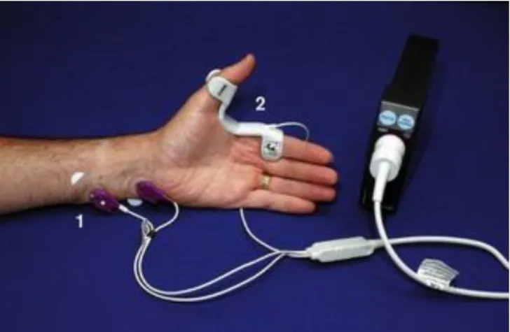
The TOF-Watch module (Figure 1.9) provides quantitative and automatic measurement of muscle response to a stimulus by the acceleromyography method. The TOF-Watch monitor was the last NMB monitor in the market that was validated for clinical research. The stimulator in the TOF-Watch is of constant current type; pulse current can be set in a range of 0-60 mA, being the default value of 50 mA. Calibration is a crucial topic as the size of responses varies from patient to patient. So, the control twitch height (i.e. twitch height when the patient is not relaxed) is set to 100% after a stimulus at 1Hz or 0.1 Hz. Available stimulation modes are TOF, PTC stimulation, DBS, Single twitch at 1Hz or 0.1 Hz, DBS and Tetanic stimulation at 50 Hz or 100 Hz. The unit displays TOF ratio %, count of number of responses after TOF, twitch height % of the last response after 1 Hz or 0.1 Hz stimulation, and PTC of detected responses. With DBS and Tetanic stimulation, only tactile evaluation can be performed to evaluate the patient’s relaxation; the display do not show response [40].
Figure 1.9 - TOF-Watch monitor. (1) Stimulating electrodes applied over ulnar nerve; (2) accelerometer
taped to thumb; (3) display screen [39].
1.6.2 – Datex-Ohmeda M-NMT
The Datex-Ohmeda M-NMT module (Figure 1.10) provides quantitative and automatic measurement of muscle response to a stimulus by the kinemyography method. The kinemyographic mechanosensor is available for adults and for paediatric use. This sensor can be detached from the device and substituted by an electrosensor which provides an
15 electromyographic evaluation of muscle response. The latter sensor is essential for the module to obtain PTC of the first electromyographic responses. This module provides a constant current supramaximal stimulus. The unit displays TOF ratio %, T1% (i.e. T1 in relation to baseline), and the number of responses after TOF and PTC. Other stimulation patterns can also be used, such as DBS and single-twitch [41]. The unit displays TOF ratio numerically on the monitor, and a bar graph of all four responses so that this ratio may be verified visually [42]. It was proven that the recovery from NMB is overestimated with kinemyography method when compared with electromyography method [43]. The lack of technical details regarding Datex-Ohmeda M-NMT module impairs the analysis of module electrical settings.
Figure 1.10 - Datex–Ohmeda M-NMT neuromuscular transmission module with kinemyographic
mechanosensor. (1) Stimulating electrodes applied over ulnar nerve; (2) piezoelectric mechanosensor [39].
Since nerve stimulation can be painful for a conscious patient, the patient should be anaesthetized before operating the stimulator [40].
In both devices, TOF is used as a standard stimulation mode. Moreover, the display screen indicates TOF ratio when the four responses are detected; in case the fourth response is not sensed, TOF ratio cannot be calculated and is only indicated the number of responses [39].
Among the available methods for objective neuromuscular monitoring acceleromyography is the most widely distributed method [44]. It is an easier monitoring method to apply comparing with the other two quantitative neuromuscular monitoring methods, i.e., kinemyography and electromyography [3].
In a study focused on comparing the TOF-ratio measured with acceleromyography (TOF-Watch) and electromyography (Datex-Ohmeda M-NMT), was verified that the first method was able to detect residual neuromuscular blockade with higher precision [45].
Recent studies carried out by Mafalda Couto (Doctoral Student in Leaders for Technological Industries – EDA, FEUP) have shown interesting data regarding limitations of current neuromuscular transmission monitors. Such drawbacks impair a correct assessment of NMB extent which has been proven to be of great value for anaesthetists; also, motivated the development of the proposed system – the goal of this project.
Preliminary clinical testing took place in Centro Hospitalar do Porto. The non-depolarizing NMD Rocuronium and the reversal drug Sugammadex were administered to patients. TOF-Watch
16
was used as monitor. Collected data is still under analysis but by far, some consistent facts were verified:
For the same patient, PTC stimulation at 50Hz induces different evoked responses that the ones found at 100Hz. It proves that patient’s evoked responses vary according to stimuli frequency. Therefore, patients may not be stimulated at the frequency that evokes the best representative responses of actual NMB extent.
The used monitor do not interpret the output. After administration of a non-depolarizing NMD, the magnitude of responses decrease from T1 to T4, sequentially. However, this fade, which represents muscle fatigue, is not always observed (e.g., T2>T1), leading to an erroneous calculation of TOF ratio and representation of muscle responses, which was not communicated to the anaesthetist.The proposed system is a neuromuscular stimulator that aims to change the paradigm of NMB assessment by providing a personalized stimulation attending to initial responses of each patient.
17
Chapter 2: Proposed device
A neuromuscular stimulator is a device used by anaesthetists for NMB monitoring. Circuits of neuromuscular stimulators were found, though those stimulators were for transcutaneous electrical nerve stimulation (TENS). TENS is used as a nonpharmacologic and noninvasive treatment for pain [46]. Therefore, the output voltage and current are much lower than the neuromuscular stimulators used in operating rooms. Most of the found circuits were analog, which is a deprecated feature for a medical device. In this sense, the presented device was designed from scratch and according to the specifications of an ideal stimulator prototype (see Table 2.1).
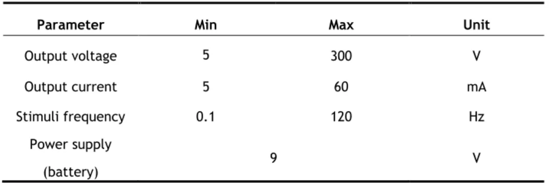
Table 2.1 – Device specifications.
The output voltage may range between 5 and 300 V to be able to provide 5-60 mA over a skin resistance that may range between 1-5 kΩ.
This device must be portable and able to connect to a tablet or computer through a USB cable. Wireless communication allows the transference of information over a distance without the use of wires, and so wireless technologies in the operating room (OR) present a lot of advantages, namely:
May minimize the electrical connections necessary for safe patient care, and enhance wireless transmission of critical medical alarms and real-time control of medical devices [47];
Reduces OR clutter by eliminating traditional cables;
Decreases risk of contamination (cables are often exposed to contamination);
Decrease repair costs (monitors are frequently damaged due to misuse of cable by OR staff; cables are damaged by wear and tear) [48];
Increase the free space in OR for a better mobility of the surgical team.
Parameter Min Max Unit
Output voltage 5 300 V
Output current 5 60 mA
Stimuli frequency 0.1 120 Hz Power supply
18
However, many studies have reported findings of electromagnetic interference (EMI) in several medical devices (e.g. defibrillators, ventilators, brain stimulators, pumps and ophthalmic equipment) caused by different types of wireless devices operating on a variety of transmission technologies including Bluetooth [49][50]. The recorded levels of EMI did not pose significant risk to life supporting medical devices. Though, have been observed EMIs described as hazardous in 12-lead ECG machines, anaesthesia monitors and echocardiogram/ultrasound machines [51].
Current instruments for monitoring the neuromuscular transmission during surgery are not wireless, and in this sense the presented device will have the same characteristic, although being now relatively easy to include this feature.
Standard Arduino boards, e.g. Uno, do not offer any wireless connection, such as Bluetooth or Wi-Fi. Yet, there are modules that enable the microcontroller board to communicate wirelessly.
The developed system main concept tackles a circuit in which is guaranteed a correctly controlled current signal - since over current can severely damage body tissues – whose waveform is according to the intended stimulation pattern chosen in a user interface. The presented circuit is composed by a 9V alkaline battery, a voltage regulator, a current source, a digital potentiometer, and a digital switch. Figure 2.1 is a representation of the developed system.
The current source integrates the circuit to yield a constant output current, whose value is controlled by the digital potentiometer. The signal from the current source is the input for the digital switch. The aim of the digital switch on the circuit is to control the output signal, being programmed to open (no signal) and to close (conducting) accordingly to the
Figure 2.1 - Diagram of the developed system.
Electrical signal Control Data transmission Legend: Current source Digital potentiometer Microcontroller Digital switch PC Electrodes Device I2C Distal electrode Proximal electrode
19 characteristics for each stimulation pattern. A voltage regulator provides the proper input voltage for the digital potentiometer since its maximum VDD is 5.5 V; it also powers the current
source and the digital switch. The microcontroller controls both digital potentiometer (via I2C
protocol) and digital switch, and communicate with an interface developed in LabVIEW. The user interface is a simple way to the anaesthetist manipulate the device to achieve the intended output. Although the output signal should be transmitted to the patient by the use of electrodes both located in the ulnar nerve, no stimulation was applied to the any human at this stage of development.
Certain components present electronic limitations that impair, a priori, the correct functioning of the device. The ideal current source should output a voltage such that the stimulator could provide the current defined by the anaesthetist regardless the skin resistance, with an input voltage of 9 V from the battery. In this sense, the signal output voltage is a parameter that will not be taken into account in the results since it is known that the desired values will not be achieved due to voltage limitations of the used current source.
Moreover, the maximum electronic current allowed by the digital switch is 30 mA, when the desired range of output current is 0-60 mA.
A theoretical explanation about each component is presented below, as well as a few practical considerations and proofs about their functioning.
2.1 – Electronic circuit
2.1.1 - Voltage regulator
A voltage regulator generates a fixed output voltage that remains steady regardless of changes to its input voltage or load conditions. There are mainly two types of voltage regulators: linear and switching [52]. The chosen voltage regulator is the L7805 fixed linear IC voltage regulator that generates fixed voltage of 5V when the load is less than 1.5 A. This voltage regulator is accompanied by a 0.33 µF electrolytic input and a 0.1 µF ceramic output decoupling capacitors. They provide a low-impedance path at the input and output of the L7805, suppress high frequency noise from the source and/or from the load (e.g. peak currents caused by rapid changes in current), reduce voltage transients on the input of the L7805, and reach electromagnetic compatibility (EMC). As the power source is a battery, the input capacitor is not a must, yet recommended. Although no output capacitor is needed for stability, the output capacitor is used to improve transient response [53].
According to datasheet, for values of output capacitance ≤ 10 µF no protection diode is required. A protection diode is used to protect the circuit from reverse voltage and current by only allowing current to flow in the forward direction and blocking current in the reverse direction. It is normally placed reverse biased in parallel with the component so if current flows through the circuit in reverse, the current flows through the diode, bypassing the L7805 [54].
20
2.1.2 - Current source
A current source is an active circuit element capable of supplying a constant current regardless of the voltage across its terminals. Ideally, a constant current source provides a constant current independently of the load connected to it [55]. The LT3092 is the chosen programmable 2-terminal current source. It needs only two external resistors; no external bypass capacitors are needed for stability [56] (see Figure 2.2). It was preferred once the output current can be set between 0.5 mA and 200mA, an adequate range of current for this project. Since this current is to be applied to the human body, the device must output the shortest range of current, yet complying the required interval of values (5-60 mA).
Figure 2.2 - Functional diagram of the LT3092 as a current source [56].
The LT3092 requires only two resistors to set a constant current. It uses a precision 10 µA reference current source and a voltage-follower circuit. This current connects to the noninverting input of an operational amplifier which provides a low impedance buffered output of the voltage on the noninverting input (see Figure 2.2). The SET node is also the input to the voltage follower, which is set up so that the voltage on the OUT pin is the same as on the SET pin [57]. A small voltage in the range of 100 mV to 1 V is generated by the reference current from the SET pin, with the RSET resistor. Such voltage is applied across ROUT. The equation (2.1)
determines the output current.
𝐼𝑂𝑈𝑇 = 𝑉𝑆𝐸𝑇 𝑅𝑂𝑈𝑇 =10 𝜇𝐴 ∙ 𝑅𝑆𝐸𝑇 𝑅𝑂𝑈𝑇 (𝑚𝐴) (2.1) Where:
IOUT is the OUT pin current;
VSET is the SET pin voltage;
ROUT is the value of the resistance connected to OUT pin;
RSET is the value of the resistance connected to SET pin.
According to equation (2.1), the output current is set by the ratio of both RSET and ROUT. So,
it is crucial to calculate the resistors. The RSET must be such that generates a voltage across
RSET between 100 mV to 1 V as mentioned above. Therefore, RSET may assume values from 10
21 errors generated in the internal constant current source and any errors in the offset voltage in the amplifier circuit are cancelled out. So, the desired RSET is 20 kΩ.
As it is necessary to obtain a variable current, RSET must be programmable to vary, such as
a digital potentiometer does. It should be chosen a 20 kΩ digital potentiometer, but attending to the available material, in this project it is used a 10 kΩ.
So, once defined the output current and the value of the potentiometer, ROUT is quickly
calculated. For the project, it was chosen a Rout equal to 1Ω so that a range of 0.5 – 100 mA could be achieved once the voltage on the OUT pin is 100mV due to RSET being equal to 10 kΩ.
2.1.3 - Digital potentiometer
The AD5241 is a 256-position digitally controlled variable resistor device with a 10 kΩ nominal resistance. A digital potentiometer is a variable resistor which is controlled by digital signals.
A potentiometer is an adjustable variable resistor with three terminals: two terminals are connected to a resistive element and the third terminal is connected to an adjustable wiper.
According to Figure 2.3, pins 1, 2 and 3 represent pins A1, wiper and B1 in AD5241. By connecting only two pins – the wiper and A1 or B1 – to the current source, the AD5142 turns a rheostat, which is its purpose on the circuit.
Figure 2.3 - Potentiometer's behaviour as a rheostat [58].
A rheostat is a two-terminal variable resistor that by changing the value of the wiper, the amount of resistance linearly increases or decreases. It is commonly used to control current by changing the value of its resistance.
As can be seen from Figure 2.3, the effective resistance is between pin B1 and the wiper. As A1 is not connected, the resistance between A1 and the wiper is open-circuited and has no effect on the load current. If both pins are connected, than that part of the resistive track is short-circuited, and so has no effect on load current.
After a brief explanation about how a potentiometer works, becomes easier to interpret the scheme of a digital potentiometer (see Figure 2.4). The digital potentiometer configuration contains CMOS (complementary metal-oxide-semiconductor) switches placed between terminals A and B. The switch selected by the digital input connects the wiper to the
22
corresponding value on the resistor string – the end-to-end potentiometer resistance. The number of resistors in the sting determines the resolution of the potentiometer [59].
Figure 2.4 - Functional diagram of the AD5241 [60].
The nominal resistance (RAB) of the AD5241 has 256 (8-bit data) contact points accessed by
the wiper terminal plus the B terminal contact. There is a minimum of 60 Ω resistance between terminal W and B due to a 60 Ω wiper contact resistance contributed by the on resistance of the internal switch. The increase of the least-significant bit (LSB) data value moves the wiper up the “resistor ladder” until the last step is reached [60]. The equation (2.2) determines the digitally programmed resistance between W and B.
𝑅𝑊𝐵(𝐷) = 𝐷
256× 𝑅𝐴𝐵+ 𝑅𝑊 (𝛺) (2.2) where:
D is the decimal equivalent of the binary code between 0 and 255 which is loaded in the 8-bit register;
RAB is the nominal end-to-end resistance;
RW is the wiper resistance.
2.1.4 - Digital switch
The chosen digital switch is the TS12A44513, a device that contains four bidirectional single-pole single-throw (SPST) single-supply CMOS analog switches. A SPST switch can control only one circuit (single pole) and the switch’s pole is connected to only one position (single throw). Two of the switches are normally closed (NC) switches and two normally open (NO) [61]. As the switches are bidirectional, NO, NC and COM pins can be used as inputs or outputs. Figure 2.5 shows the functional diagram of the device.
23 Figure 2.5 - Functional diagram of the TS12A44513 [61].
It is recommended that the digital control pin (IN) be pulled up to VCC or down to GND to
avoid undesired switch positions (see Figure 2.6). According to Figure 2.6, the pre-set values of the resistor and capacitor connected to COM pin result in a switching time of about 10 ns.
Figure 2.6 - Circuit of the TS12A44513 [61].
2.2 - Practical considerations
2.2.1 - Test equipments
The test equipments used during the development of the project were: the Velleman LABPS23023 Dual DC Lab Power Supply, the Kaise MY-64 multimeter, the Tenma 72-1020 bench digital multimeter, and the Rigol DS1054Z digital oscilloscope 50 Mhz DSO 4 Channels.
2.2.2 - Voltage regulator
The voltage regulator circuit converts the 9V from the power supply (alkaline battery) to 5V. Figure 2.7 shows the schematic drawn in Eagle.
24
2.2.3 - Digital potentiometer
To test the digital potentiometer wiring, a test setup was performed. In this matter, it was measured the resistance with a multimeter, for different values set for the wiper. Using the equation (2.2), it is possible to compare the experimental and the expected resistance. Table 2.2 shows the obtained results.
Table 2.2 - Expected and measured resistance values.
Expected resistance value (Ω) Measured resistance values (Ω)
60 42 99 75 451 427 2013 1990 3966 3940 5919 5900 7873 7860 9826 9800 10021 10002 Mean error (%) 6,81
This test was performed to ensure the correct input voltage to the current source component. Therefore, after demonstrating the AD5241 was operational, it could be connected to the current source.
2.2.4 - Current source
As previously mentioned, the current source regulates the output current based on two resistors. In this project, those resistors are a 1 Ω resistor and a 10 kΩ digital potentiometer. Attending to equation 2.1, varying the resistance provided by the digital potentiometer, output current may range from 0 up 100 mA, ideally. Figure 2.8 shows how the output current changes with the digital potentiometer when using an ROUT equal to 1 Ω.
25 The tendency curve presented on Figure 2.8 was used to predict the wiper value when the user selects a specific stimulation current. Its equation is showed below:
𝑂𝑢𝑡𝑝𝑢𝑡 𝑐𝑢𝑟𝑟𝑒𝑛𝑡 = 0,3861 ∙ 𝑤𝑖𝑝𝑒𝑟 𝑣𝑎𝑙𝑢𝑒 + 0,482 (𝑚𝐴) (2.3)
where:
Output current is the current value selected by the user on the interface; Wiper value varies between 0 and 255.
The stimulation current is correctly programmed since a small mean error of 1,67% between the expected and experimental values was calculated.
To predict the current behaviour when the signal is applied on the human skin, was placed a load in the output of the current source. The load is a resistor with a value in the range of the skin resistance. The tested resistance values were 1,2 kΩ and 3,3 kΩ. As the voltage is limited, when a load is added, the maximum output current decreases as the load resistance increases, according to Ohm’s law (see Figure 2.9).
0 20 40 60 80 100 120 0 50 100 150 200 250 300 O ut put cur rent ( m A ) Wiper value
Figure 2.8 - Output current according to the wiper value.
0 0,5 1 1,5 2 2,5 3 3,5 0 50 100 150 200 250 300 O utp ut cu rr ent (m A ) Wiper value R = 1,2 kΩ R = 3,3 kΩ
26


![Figure 1.9 - TOF-Watch monitor. (1) Stimulating electrodes applied over ulnar nerve; (2) accelerometer taped to thumb; (3) display screen [39]](https://thumb-eu.123doks.com/thumbv2/123dok_br/15711268.1069052/32.892.263.582.530.921/figure-watch-monitor-stimulating-electrodes-applied-accelerometer-display.webp)

![Figure 2.3 - Potentiometer's behaviour as a rheostat [58].](https://thumb-eu.123doks.com/thumbv2/123dok_br/15711268.1069052/39.892.204.679.574.809/figure-potentiometer-s-behaviour-rheostat.webp)
![Figure 2.4 - Functional diagram of the AD5241 [60].](https://thumb-eu.123doks.com/thumbv2/123dok_br/15711268.1069052/40.892.261.605.146.513/figure-functional-diagram-ad.webp)

