978-1-4799-5743-9/14/$31.00 ©2014 IEEE
FFC NMR Relaxometers on Education
Topologies, control techniques and electromagnetic devices
António Roque and José Maia
Department of Electrical Engineering
ESTSetúbal - Instituto Politécnico de Setúbal & INESC-ID Setúbal, Portugal
[email protected], [email protected]
Duarte M. Sousa and Gil Marques
Department of Electrical and Computer Engineering INESC-ID
Instituto Superior Técnico – Universidade de Lisboa Lisboa, Portugal
[email protected], [email protected]
Elmano Margato
Centro de Electrotecnia e Electrónica Industrial ISEL &INESC-ID
Lisboa, Portugal [email protected]
Pedro José Sebastião
Dep. de Fisica & Condensed Matter Physics Center (IST site) Técnico Lisboa – University of Lisbon
Lisboa, Portugal
Abstract—The Fast Field Cycling (FFC) Nuclear Magnetic
Resonance (NMR) equipment has been mainly developed by engineers with a strong background in power electronics, control and physics. This technique has been widely used by physicists, chemists, biologists, pharmacists and food analysts. During the last decades, the development of this type of apparatus has been taking advantage of the power semiconductors, topologies of the power electronic converters, control techniques, computational tools and materials, among other aspects. In this paper, teaching aspects of using this type of equipment and technique in courses of physics and electrical engineering is described.
Keywords—power electronics; control; semiconductors; experiment; computational tools
I. INTRODUCTION
Fast Field Cycling (FFC) Nuclear Magnetic Resonance (NMR) is an experimental and powerful technique used to study the molecular dynamics of different types of compounds [1-4]. The main modules of a FFC NMR apparatus, represented in Fig. 1, are:
- Power supply/Current source; - Magnet;
- Control;
- Radio frequency system; - Computer/Software; - Temperature controller.
During the last decades, different solutions for each module have been developed. If during the early days of the technique this equipment was operated manually and was constituted by mechanical parts, the most recent solutions incorporate advanced electronic circuits and can also be digitally controlled. Furthermore, efficient and portable solutions have been developed [5-8].
Fig. 1. Main modules of a FFC NMR apparatus.
As main requirement of FFC NMR equipment, the magnet current (iM) needs to be controlled in order to cycle as shown in
Fig. 2. Typical current cycle of a FFC NMR equipment.
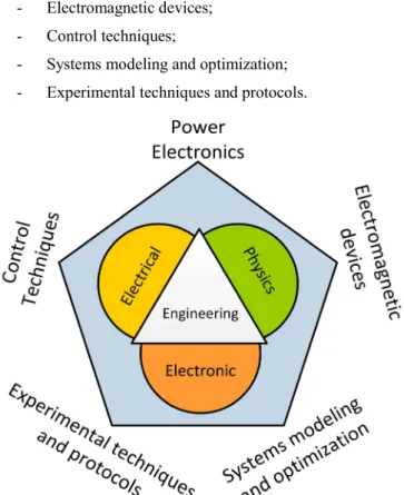
This type of equipment has been designed by teams joining Electrical, Electronic and Physics Engineers, which should have skills in the following topics (Fig. 3):
- Power electronics; - Electromagnetic devices; - Control techniques;
- Systems modeling and optimization; - Experimental techniques and protocols.
Fig. 3. Main topics related with FFC NMR equipment.
In general, the Electrical and Electronic Engineers are very active during the design and optimization phases. The Physics Engineers have an important role defining the specifications of the equipment, testing and validation phases.
The developed prototypes are, in general, installed in NMR laboratories and have been used by master and PhD students’ and senior researchers from different areas, as for instance, physics, chemistry, biology, medical sciences and food industry. Furthermore, it has been also used as a platform to teach electric circuits equipment in Electrical Engineering and Physics Engineering courses.
II. ELECTRIC CIRCUITS
One of the core elements of the FFC NMR equipment are the power supplies, which have been improved taking advantage of several technological aspects. Starting with the topologies used at the early days of the technique and crossing the different known solutions [5-11], the FFC NMR power supplies are an effective tool to teach:
- Electric circuits design and analysis (RL, RLC, …); - Semiconductors (Bipolar transistor, GTO, IGBT,
MOSFETS, …). - Protection circuits.
A circuit implemented in the early days of the FFC NMR technique is shown in Fig. 4. This circuit uses variable resistors to change the magnet current and a switch (S) in order to commute the magnet current.
Fig. 4. Electric circuit with variable resistors and a switch.
The electric equation corresponding to the Fig. 4 circuit is:
(1) Being,
0
1 (2)
Other circuits and topologies used as power circuits of FFC NMR apparatus are represented in Fig. 5, Fig. 6 and Fig. 7.
Fig. 5. Electric circuit with semiconductors in parallel.
The solution shown in Fig. 5 is an interesting solution since semiconductors (IGBTs) are placed in parallel. In this case the collector-emitter voltage (VCE) of the IGBT is proportional to
the gate-emitter voltage (VGE) in order to c
current. The corresponding electric equation i
Where vAK is the drop voltage in the diod
number of IGBTs in parallel.
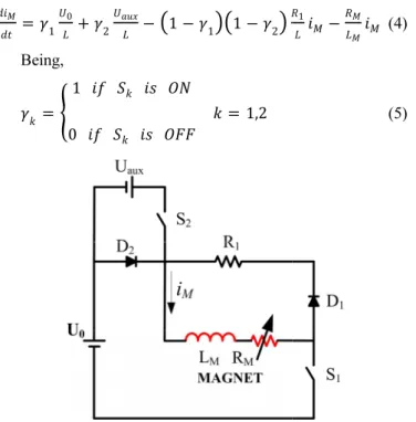
In Fig. 6, a topology based on a chopp solution had allowed reducing the volum solutions. This topology was implemented NMR equipment.
In this case, the dynamics of the magnet c the states γ1 and γ2 of the switches S1 and S2, r
1 0 2 1 1 1 2 Being, 1 0 1,2
Fig. 6. Solution based on the chopper circuit.
Fig. 7. Solution that can have IGBTs or MOSFETs. In Fig. 7 is shown the circuit impleme recent prototype. This solution is very simil requires only a power semiconductor (S) (thi either an IGBT or a MOSFET).
control the magnet is:
(3) de D1 and n is the
per is shown. This me of the existing d in portable FFC current depends on respectively: 1 (4) (5)
ented in the most ar to Fig. 5, but it is solution can use
In addition to the referred supplies that use GTOs and developed [3].
The solutions based on p relevant since the power semi commutation and protection ci circuit in Fig. 7 but including diode is shown in Fig. 8.
Fig. 8. Solution that can have IGBTs III. ELECTROMAGNETIC TECHN Other important issue r equipment is the magnet desi cored solenoids manufactured [10-11] or can be electromagne Usually, the design of knowledge of optimization tech Two examples of FFC magn Fig. 10. These solutions are c been taking advantage of mater as for instance, the iron or the c
Fig. 9. FFC NMR electromagnet.
d solutions, FFC NMR power power bipolar transistors were
power semiconductors are also iconductors require, in general, ircuits. A solution based on the a snubber, a filter and a Zener
or MOSFETs with protection circuits. DEVICES AND OPTIMIZATION NIQUES
related with the FFC NMR gn. These magnets can be air-with aluminum or copper [1-4], ets [5-7].
these magnets requires the hniques and programming skills. nets are shown in Fig. 9 and conceptually different and have rials with distinct characteristics, copper.
Fig. 10. FFC NMR air cored magnet (solenoid type). As example of the continuous evolution a FFC NMR magnets, the configuration of a r includes superconducting parts, is shown, in F
Fig. 11. Electromagnet with superconductors. About the design of FFC NMR magnets refer that this topic can be a useful tool tea optimization techniques and electromagn addition, it is used as an example of a rea incorporates different materials, which h electromagnetic properties.
IV. CONTROL To control the current as required by the 12), different control techniques have been be Using as reference the topologies referred following types of controllers were implemen
- PI (proportional and integral actions) - PD2I (proportional, derivative a
actions);
- Two levels hysteretic controller; - Three level hysteretic controller. As first approach, for the tuning of th generic block diagram represented in Fig. 12
Where C(s) represents the controller tran G(s) represents the transfer function of analysis (in general, a 2nd or 3rd order system)
To control the current of the circuit repre PI controller was used.
and optimization of recent solution that
Fig. 11.
, it is important to aching algorithms, netic devices. In
al application that have also distinct
e application (Fig. e used [12-14]:
d in section II, the nted:
;
and two integral
he controllers, the can be used. nsfer function and
the circuit under ).
esented in Fig. 5, a
Fig. 12. General control diagram. Since the Fig. 7 circuit is m is required. In this case, the cir order optimized transfer functio
The transfer function of the
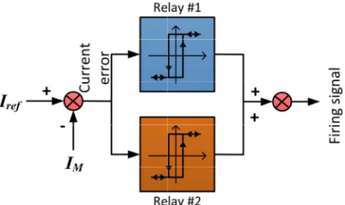
The parameters of the PI a using ITAE criteria and root loc For other hand hysteretic co to control the current of the top level hysteretic controller is us depend on the current error as r
Fig. 13. Block diagram of a three level For the design of the hyster fulfil the requirements of the considers the effect of changing
- the maximum swi
semiconductors; - the current ripple allow - the natural time con imposed by the magnet About the controllers, it is solutions can be found in the during the courses, the students the analog solutions by dig microcontrollers.
V. CONCLUSIONS In this paper are summarize in graduation courses of Elec Engineering based on the evolu
more complex, a PD2I controller rcuit can be represented by a 3rd
on:
(6) PD2I controller is:
(7) and PD2I controllers can be set
ci methods.
ontrollers, in Fig. 13, were used pology in Fig. 6. In this case, a 3 sed, which joins two relays that represented in Fig. 13.
hysteretic controller.
retic controllers, and in order to e application, the methodology g:
itching frequency of the
wed; and
nstant of the system (usually t).
s important to refer that analog e existing prototypes. Anyway, s have the opportunity to replace gital ones based on low cost
S AND FINAL REMARKS
ed some aspects and topics used ctrical Engineering and Physics ution of FFC NMR equipment.
Other aspects could be referred, as software used to control the equipment and experimental protocols, experimental proced and data fitting.
Other important aspects addressed in t Physics courses are the modeling, simulat behavior analysis of electric circuits. In Fig electric circuits that are studied and compare represented in Fig. 4 and Fig. 6, respectively,
Fig. 14. Electric circuit with variable resistors, a capacit When analyzing electric circuits, for the c is interesting to design the capacitor CS and
influence of CS in the running of this circu
with the solution in Fig. 4.
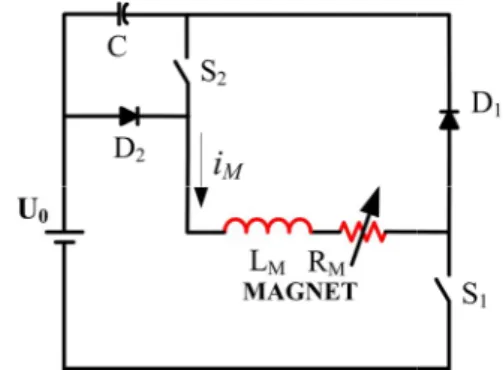
Fig. 15. Solution based on the chopper circuit and energ Another important topic that can be taug NMR power supplies is the energy recovery. energy that can be used to charge capacitor circuit in Fig. 6, for instance) when the c down. The stored energy can be reused when up, improving the global efficiency of the sys
As remark, it is important to point o elements of the FFC NMR equipment, the ma power supply, has been used in Electr Engineering courses of different levels following topics:
- Electric circuits theory;
- Semiconductors types and operating p - Protection and commutation circuits; - Electromagnetic devices design; - Optimization techniques; - Programming;
- Electromagnetic properties of materia
for instance, the d to implement the dures, data analysis
the Electrical and tion and dynamic g. 14 and Fig. 15, ed with the circuits
are shown.
tor and a switch. circuit in Fig. 14 it
to characterize the uit when compared
gy recovery.
ght using the FFC The magnet stores rs or batteries (see current is stepping n the current steps stem.
out that the core agnet and the main rical and Physics s addressing the
principles;
als;
- Control techniques; - Modelization and simu
As final remark, in Table I researchers involved with the F equipment available at Instituto average per year from 2008 should be referred that the Ele been mainly involved in th improvement of the equipme people have been performing F contributing to improve this te been only getting experimental TABLE I. NUMBER OF PEOPLE
DEVELOPMENT OF THE EQUIPMENT (
MSc students Electrical Engineering 4 Physics Engineering 5 Other 4
For example, the Physics opportunity to measure parame dynamics of different compo context, a typical experiment is lattice relaxation time (T1) of
aging of wines produced in sim soils, for instance), as represent
Fig. 16. Spin-lattice relaxation time (T1
ACKNOWL This work was supported b Fundação para a Ciência e a OE/EEI/LA0021/2013.
REFER [1] F. Noack, “NMR Field-Cyc Applications”, Prog. NMR Spectr [2] R. Seitter, R. O. Kimmich, “
Encyclopedia of Spectroscopy
London, pp. 2000-2008, 1999. [3] E. Anoardo, G. Galli, G.
Applications and Instrumentatio 20, pp. 365-404, 2001.
lation.
I are summarized the number of FFC NMR technique (using the o Superior Técnico – Lisbon) in to 2013. About these figures, ectrical Engineering people have he development and technical
ent. The Physics Engineering FFC NMR experiments and also echnique. The other people have
results.
E PERFORMING EXPERIMENTS AND/OR
(IN AVERAGE PER YEAR –2008-2013)
PhD students Researchers Senior
1 2 2 2 2 3
Engineering students have the eters related with the molecular ounds. Within the Portuguese s performed measuring the spin-f wines, allowing to check the
milar conditions (as grapes and ted in Fig. 16 [15].
1) of wines.
LEDGMENT
by national funds through FCT – Tecnologia, under project PEst-RENCES
cling Spectroscopy: Principles and
rosc., vol. 18, pp. 171-276, 1986.
“Magnetic Resonance: Relaxometers”,
and Spectrometry, Academic Press,
Ferrante, “Fast-Field-Cycling NMR: on”, Applied Magnetic Resonance, vol.
[4] R. Kimmich and E. Anoardo, “Field-Cycling NMR relaxometry”,
Progress in NMR Spectroscopy, 44, pp. 257-320, 2004.
[5] J. Constantin, J. Zajicek, F. Brown, “Fast Field-Cycling Nuclear Magnetic Resonance Spectrometer”, Rev. Sci. Instrum., vol. 67, pp. 2113-2122, 1996.
[6] D. M. Sousa, P. A. L. Fernandes, G. D. Marques, A. C. Ribeiro, P. J. Sebastião, “Novel Pulsed Switched Power Supply for a Fast Field Cycling NMR Spectrometer”, Solid State Nuclear Magnetic Resonance, vol. 25, pp. 160-166, 2004.
[7] D. M. Sousa, G. D. Marques, J. M. Cascais, P. J. Sebastião, “Desktop Fast-Field Cycling Nuclear Magnetic Resonance Relaxometer”, Solid
State Nuclear Magnetic Resonance, vol. 38, pp. 36-43, 2010.
[8] A. Roque, S. F. Pinto, J. Santana, Duarte M. Sousa, E. Margato, J. Maia, “Dynamic Behavior of Two Power Supplies for FFC NMR Relaxometers”, IEEE International Conference on Industrial Technology – ICIT 2012, Athens - Greece, 2012.
[9] A. G. Redfield, W. Fite, H. E. Bleich, “Precision High Speed Current Regulators for Occasionally Switched Inductive Loads”, Review of
Scientific Instruments, vol. 39, pp. 710-715, 1968.
[10] D. M. Sousa, E. Rommel, J. Santana, J. Fernando Silva, P. J. Sebastião, A. C. Ribeiro, “Power Supply for a Fast Field Cycling NMR Spectrometer Using IGBTs Operating in the Active Zone”, 7th European Conference on POWER ELECTRONICS AND APPLICATIONS, , Trondheim, Norway, pp. 2.285-2.290, 1997.
[11] D. M. Sousa, G. Marques and P. J. Sebastião, “Reducing the size of Fast Field Cycling NMR Spectrometers based on the use of IGBTs”, “IEEE ICIT 2009 - International Conference on Industrial Technology”, Churchill - Australia, February 2009.
[12] A. Roque, D. M. Sousa, E. Margato, J. Maia and Gil Marques, “Control and Dynamic Behaviour of a FFC NMR Power Supply - Power Consumption and Power Losses”, IECON 2013 – 39th Annual Conference of the IEEE Industrial Electronics Society, Vienna, Austria, 2013.
[13] K. Ogata, “Modern Control Engineering”, 5th Edition, Prentice-Hall, 2010.
[14] J. J. D'Azzo and C. H. Houpis, “Linear Control System Analysis and Design: Conventional and Modern”, 4th Edition, McGraw-Hill, 1995. [15] A. Roque, Duarte M. Sousa, P. J. Sebastião, “Fast Field Cycling NMR
Relaxometer: Featuring Wines”, 7th Conference on Field Cycling NMR Relaxometry, Torino - Italy, June 2011.