Repositório ISCTE-IUL
Deposited in Repositório ISCTE-IUL:
2019-01-08Deposited version:
Publisher VersionPeer-review status of attached file:
Peer-reviewedCitation for published item:
Matos, S. A., Naseri, P., Teixeira, J. M., Costa, J. R. & Fernandes, C. A. (2018). New concept for multibeam antennas based on two cascaded Ka-band transmit-array. In 39th ESA Antenna Workshop on Innovative Antenna Systems and Technologies for Future Space Missions. Noordwijk
Further information on publisher's website:
--Publisher's copyright statement:
This is the peer reviewed version of the following article: Matos, S. A., Naseri, P., Teixeira, J. M., Costa, J. R. & Fernandes, C. A. (2018). New concept for multibeam antennas based on two cascaded Ka-band transmit-array. In 39th ESA Antenna Workshop on Innovative Antenna Systems and
Technologies for Future Space Missions. Noordwijk. This article may be used for non-commercial purposes in accordance with the Publisher's Terms and Conditions for self-archiving.
Use policy
Creative Commons CC BY 4.0
The full-text may be used and/or reproduced, and given to third parties in any format or medium, without prior permission or charge, for personal research or study, educational, or not-for-profit purposes provided that:
• a full bibliographic reference is made to the original source • a link is made to the metadata record in the Repository • the full-text is not changed in any way
The full-text must not be sold in any format or medium without the formal permission of the copyright holders.
Serviços de Informação e Documentação, Instituto Universitário de Lisboa (ISCTE-IUL) Av. das Forças Armadas, Edifício II, 1649-026 Lisboa Portugal
Phone: +(351) 217 903 024 | e-mail: [email protected] https://repositorio.iscte-iul.pt
NEW CONCEPT FOR MULTIBEAM ANTENNAS BASED ON TWO CASCADED
KA-BAND TRANSMIT-ARRAYS
S. A. Matos (1), P. Naseri (2), J. M. Teixeira(1) , J R. Costa(1), C. A. Fernandes(2)
(1) Instituto Universitário de Lisboa, (ISCTE-IUL), Lisbon, Portugal, [email protected] (2) Instituto de Telecomunicações, Instituto Superior Técnico, IT/IST, Lisbon, Portugal
Abstract – The paper presents a new two-beam per-feed approach for Ka-band multi spot-beam satellites. It is based on a dual-stacked transmit array (TA) arrangement, fed by a 3×3 standard waveguide array. The TAs are co-designed so that the first performs a beam collimation and tilting; whereas the second splits the incoming beam into two orthogonal circular polarizations, with symmetrical output angles relative to the incident angle. Therefore, the number of feeds is half the number of output beams, and the linearly polarized feed reduces significantly the antenna complexity. As a proof-of-concept, we design an antenna for the 30 GHz up-link band. The focal length of the first TA is 50 mm, and the aperture size of both TAs is 196×148 mm. A new type of phase correction, the multifocal approach, is used to minimize aberrations for all beams, which would be otherwise impossible with such low F/D. Using full-wave simulations, we confirm that the 18 beams present low SLL (~15 dB), pure circular polarization and good crossover (~3 dB) with gains between 21 and 22 dBi.
I. I
NTRODUCTIONWith the advent of new broadband communication systems envisaging massive constellations of LEO small satellites [1], multibeam antennas assume a central role. The antenna design, already a challenging process, must be further bounded by cost and size requirements. The typical single feed per beam strategy for high-density beam systems [2], usually implies that adjacent beam crossover level falls well below −3 dB, creating blind coverage regions. This is due to the minimum spacing required between feeding elements imposed by their physical dimensions. On the other hand, multi-feed-per beam arrays use very complex beamforming networks that affect the cost and efficiency of the antenna, especially at Ka-band [3]. Another important limiting factor for the antenna performance is the mutual coupling between feeds.
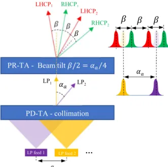
In this work we present a new configuration operating in the Ka-band, that offers two beams per feed, with orthogonal circular polarization. The working principle is presented schematically in Figure 1. A set of linear polarized primary feeds, that form the antenna feeding
network, illuminates a transmit-array formed by phase-delay cells, that produces collimated beams pointing at different directions 𝛼 . The linear to circular polarization conversion is achieved by using a second TA, formed by phase rotation cells, that splits the incoming beam into two beams with orthogonal circular polarization. This TA is designed to introduce an angular offset of 𝛽 2⁄ in the elevation plane. Because this TA uses phase rotation unit cells, [5], the right- and left-polarization components of the incident wave undergo the same angular shift but in symmetric directions, thus providing the aforementioned beam splitting. By choosing 𝛽 = 𝛼 2⁄ we get a uniform spacing between adjacent beams (equal to 𝛽) with orthogonal circular polarizations, as represented in the inset of Figure 1.
The angular separation between beams depends on the relative distance 𝑎 of the corresponding primary feeds, Figure 1b. In [4], we show that it is possible to estimate the angular separation of the beam as function of the 𝑎/𝐹 ratio for an offset Fresnel correction. The collimated beams are expected to present similar shape for all feed elements. However, for the usual Fresnel phase correction [4], aberrations build-up as the corresponding feed position increases relative to the TA focal point. This effect is more noticeable for lower focal distances.
The proper choice of the focal distance depends on several factors. First, it must be low enough to avoid excessive spillover from the feeding network. We should stress that, the aperture size of each primary feed (and consequently it’s directivity) is limited by the physical space required to juxtapose the elements in the feeding network. Secondly, the focal distance also affects the beam tilt angle, thus affecting the crossover performance. One should keep in mind that for a given displacement 𝑎 between adjacent feeds, different angular shifts are obtained as the focal distance varies [4]. Finally, the focal distance must be kept as low as possible to provide a compact antenna solution. Herein, we present a new method for designing the transmit-array – the multifocal approach – that allows extremely low focal distances. The designed TA has an 𝐹/𝐷 = 0.34, where 𝐷 = 145 𝑚𝑚 is the smallest aperture dimension.
The proposed configuration allows greatly reducing the complexity of the feeding network and coping with the limited space for the feeds: first, the number of feeds is reduced by half; secondly, each element has linear polarization. The feeding system simplicity also paves the way to achieve good port isolation. Herein, we use a
39th ESA Antenna Workshop on Innovative Antenna Systems and Technologies for Future Space Missions 02-05 October 2018, Noordwijk, The Netherlands
standard Ka-band waveguide (WR28) as the primary feed element. As a proof-of-concept we considered the feeding network to be 3x3 matrix, which corresponds to a 18-beam system with orthogonal circular polarization between adjacent cells. The assessment of the antenna performance is based on full-wave simulations.
This document is organized as follows: in Section II we describe the design of the multifocal TA; in Section III we focus on the design of the PR-TA for linear to circular polarization beam splitting; in Section IV we present the performance of the complete system; Finally the conclusions are outlined in Section V.
Figure 1: Working principle of the proposed multibeam antenna.
II.
M
ULTIFOCALP
HASED
ELAYTA
A. Desing
A TA is composed by a collection of local spatial filters (the unit cells) properly assembled according to a prescribe phase shift function, Φ , usually forming a planar aperture. Throughout this work, we consider that the 𝑥𝑦 − plane contains the TA aperture. The traditional spherical-to-plane wave conversion that provides boresight beam collimation is set by the phase shift function
Φ = 𝑘 (𝑥 − 𝑥 ) + 𝑦 + 𝐹 (1) where 𝑘 is the free-space wave number, 𝑥 is x-position of the TA focus and 𝐹 is the focal distance. This design can be generalized to produce an off-axis outgoing beam that points to the zenithal angle 𝛼 as
Φ =Φ𝑙𝑒𝑛𝑠 𝑏𝑜𝑟𝑒𝑠𝑖𝑔ℎ𝑡
−𝑘 sin 𝛼 𝑥 (2) Additional zenithal beam tilt results from moving along 𝑥 the primary feed that illuminates the TA. However, this displacement also introduces other aberrations. In [4] we present general design rules for finding the proper TA dimensions that favor low beam distortions within the scanning region. Furthermore, in [4] we show that the offset Fresnel correction (2) enables quite wide beam
scanning: [-50º,50º] scanning range within a 3dB scan loss for 𝐹/𝐷 = 0.7 at Ka-band.
Herein, we presented a new phase correction function (that we designate as the multifocal design) for further reducing the focal distance while keeping the same aperture size and scanning range. In the multifocal approach, instead of having only a well-defined focus, the TA has several pseudo-foci. In this way, the intrinsic phase error caused by feed displacement can be smeared among all beams rendering a more uniform TA performance within the scanning range. The corresponding phase shift function is defined as a weighted sum of 𝑁 offset Fresnel corrections with different foci 𝑥 and exit angles 𝛼
Φ = 𝑊 Φ (3)
The weight factors are Gaussian functions centered in the pseudo-focus positions to account for the non-uniform illumination of the feed
W = 𝑒
The standard deviation 𝜎 is adjusted to best fit the illumination intensity in the TA imposed by the primary feed. The number of foci, the focus positions 𝑥 and the corresponding exit angles 𝛼 , with 𝑖 = 1, . . 𝑁 are all unknowns that need to be optimized. A systematic way to define these parameters will be presented elsewhere.
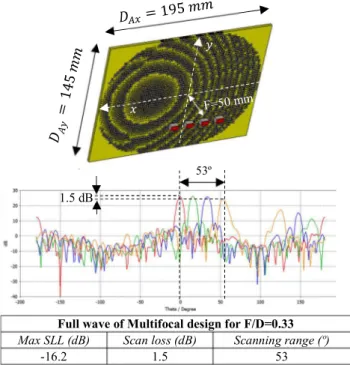
We compare in Figure 2 the TA scanning performance with unifocal Fresnel correction and multifocal correction, for a 𝐹/𝐷 = 0.34 and aperture size a 195 × 145 𝑚𝑚 (the same as in [4]). At this point we use an analytical phase representation, and PO/GO analysis. It is clear that the multifocal approach provides the best overall performance of the TA within the 50º scanning range.
PO/GO analysis of Unifocal design for F/D=0.34 Max SLL (dB) Scan loss (dB) Scanning range (º)
-3.2 6.2 52 0 5 10 15 20 25 30 35 -20 0 20 40 60 80 D ire ct iv vi ty (d Bi ) Theta [deg]
PR-TA - Beam tilt 𝛽/2 = 𝛼 4⁄
Escreva uma equação aqui.
LP feed 1 LP feed 2 PD-TA - collimation 𝑎 𝛼 𝛽 𝛽 LHCP1 RHCP1 RHCP2 LHCP2 LP1 LP2 … 𝛼𝑎
𝛽
𝛽𝛽
𝛽
PO/GO analysis of multifocal design for F/D=0.34 Max SLL (dB) Scan loss (dB) Scanning range (º)
-11.8 2.6 51
Figure 2: Comparison of the scanning performance of the multifocal and the unifocal Fresnel designs, considering the same aperture size
(195x148 mm2) and focal distance (50 mm) using PO/GO.
The performance of a TA with real PD cells and multifocal phase correction was analyzed by full-wave. The TA has the same aperture size and the same unit cells and as in [4]. The results are presented in Figure 3. The overall performance of the TA behaves as expected. However, when comparing with the PO/GO analysis, the directivity is lower, which can be explained by the local details of the real unit cells behavior that are not captured in the PO/GO analysis. These effects are particularly important as we are working with an extremely low F/D ratio (0.34). On the one hand, the low F/D ratio implies that a significant portion of the cells are required to operate for high angles of incidence (that were not initially considered for the unit cell design). Furthermore, the used F/D imposes fast phase variations and several 360º phase transitions, which degrade the TA performance. We should stress that in principle better results could be obtained with a new unit cell design. Nevertheless, the provided example is enough as a proof of concept.
Figure 3: Full-wave analysis of a multifocal TA for a focal distance of 50 mm and considering the same unit cells and aperture size (195x148
mm2) as in [4].
B. Multibeam configuration
In this section we assess the mutifocal TA performance in the context of a multibeam antenna by illuminating the aperture with a 3x3 matrix of WR28 waveguides (see Figure 4). A 26 dBi gain is achieved for all beams (±0.5 𝑑𝐵). The isolation between ports is below -15 dB. The vertical elements of the feeding matrix produce a set of beams with a suitable crossover level (-3dB). Nevertheless, the horizontal elements correspond to beams that have a crossover level well below this value (-6 dB). In this direction, the feeding elements are separated by 𝑎 = 9.112 𝑚𝑚 which lead to an angular shift of 𝛼 = 10° between adjacent beams. Thus, this configuration cannot provide continuous coverage. In the next section, we will show that by adding an additional TR it is possible to solve two problems: get orthogonal circular polarizations between adjacent beams and have crossover level below 3dB in both planes.
Figure 4: a) Multibeam configuration of the TA illuminated by a 3x3 matrix of WR28 waveguides. b) radiation pattern (gain) for 𝜑 = 0°
considering the 3 feeding elements in the central line . c) radiation pattern (gain) for 𝜃 = 34° considering the vertical central line of the
feeding matrix.
III.
P
HASER
OTATION-TA
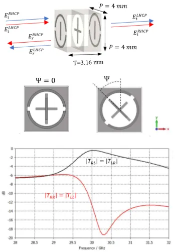
TA unit cells can be grouped in two main categories: phase rotation (PR) and phase delay (PD). A thorough comparison between these two designs can be found in [5]. Herein, we adopted a similar unit cell geometry as in [5], see Figure 6. The transmission characteristics for circular polarization of the designed PR unit cell are also presented in Figure 6 according to 0 5 10 15 20 25 30 35 -20 0 20 40 60 80 D ire ct iv ity (d Bi ) Theta (deg) 53º 1.5 dB
Full wave of Multifocal design for F/D=0.33 Max SLL (dB) Scan loss (dB) Scanning range (º)
-16.2 1.5 53 𝑦 𝑥 3x3 WR28 waveguide matrix a) 6 𝑑𝐵 b) 3 𝑑𝐵 c) 𝛼 = 10° 𝜃 = 34° 𝜑 = 0°
39th ESA Antenna Workshop on Innovative Antenna Systems and Technologies for Future Space Missions 02-05 October 2018, Noordwijk, The Netherlands
𝐸 𝐸 = 𝑻 ∙ 𝐸 𝐸 where 𝑻 = 𝑇𝑇 𝑇𝑇 ~𝑇 0 𝑒 𝑒 0
The rotation angle of the unit cell, defined as Ψ (see Figure 6) is responsible for controlling the phase of transmitted circular polarization wave. One particularity of this approach is that the phase shifts provided by the unit cell for the RHCP and LHCP are symmetric. This property allows creating a PR-TA that acts as a beam splitter, converting a linear polarization into two circular polarized beams through the phase shift function
Φ =−𝑘 sin𝛽 2𝑥 =
−𝑘 sin(𝛽 2⁄ )𝑥 for RHCP 𝑘 sin(𝛽 2⁄ )𝑥 for LHCP (4) As explained previously, the PR-TA beam tilt (𝛽 2⁄ ) should be 𝛼 ⁄4 . According to Figure 4 we need to design this transmit-array for an angular shift of 2.5 degrees. A similar aperture size to the PD-TA was considered for the PR-TA, see Figure 6.
Figure 5: PR unit cell and corresponding transmission coefficients.
Figure 6: Designed PR-TA for Φ = −𝑘 sin(𝛽 2⁄ )𝑥 with 𝛽 2⁄ = 2.5°.
IV. C
OMPLETEM
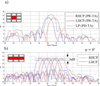
ULTIBEAM ANTENNA CONCEPTThe complete system of the two TA and feeding network is depicted in Figure 7. We choose the distance between the two TA to be 20 mm which was sufficient to decouple these two structures. Nevertheless, further studies can be conducted to find the optimal distance. In Figure 8 a) we can compare the radiation pattern of beam coming from the PD-TA with the final radiation pattern after beam splitting. The results agree with the design values. We should stress that the 4 dBi gain drop from the PD-TA to the PR-TA (from 26 dBi to 22 dBi) is also expected. Ideally, the energy is splitted in half (-3dB), the remain 1 dB difference can be justified by the insertion losses of the PR-TA and residual coupling between the two TAs. In Figure 8 b) we confirm that the crossover level that was -6 dB is now kept within the acceptable margin of 3dB. The coverage in this plane ranges from 22 to 46 degrees but can be easily extended by simply increasing the number of feeding elements.
Figure 7: Proposed multibeam configuration 𝑃 = 4 𝑚𝑚 𝑃 = 4 𝑚𝑚 |𝑇 | = |𝑇 | |𝑇 | = |𝑇 | 𝐸 𝐸 𝐸 𝐸 𝐸 𝐸 Ψ Ψ = 0 𝐷 = 1 4 8 𝑚 𝑚 𝑑 = 20 𝑚𝑚 𝐹 = 50 𝑚𝑚 PD-TA PR-TA
Figure 8: Radiation pattern (gain) of the multibeam antenna: a) comparison of the split circular beams with the original LP beam for the
central element of the feeding network; b) cross over level considering all element of the central line of the feeding network.
V. C
ONCLUSIONSWe have successfully demonstrated that using a cascade of appropriately designed phase delay and phase rotation TAs it is possible to achieve a dual-beam per feed antenna system for multi-spot satellites. An array of linearly polarized waveguide feeds used with this TA arrangement produces twice more beams than the number of feeds, the adjacent beams presenting orthogonal polarization. A large burden associated with the design of the feeding network is removed, thus introducing a great deal of simplicity in the design of this antenna, which translates into low cost and high radiation efficiency.
In the presented example, we test a system fed by 9 waveguides WR28 arranged in a 3x3 matrix. The antenna produces 18 beams with continuous coverage between 22º and 46º in elevation plane with a gain of 21 dBi relative to the power provided to each feeding element. The proposed concept is very attractive for low-cost LEO and MEO satellites. The design has potential to accommodate other specifications suitable for the next generation of the satellite communications.
VI. R
EFERENCES
[1] B. Leahy, “SpaceX seeks permission for 4,425-satellite internet constellation”, Splaceflight Insider webarticle November 19, 2016.
[2] N. Llombart, A. Neto, G. Gerini, M. Bonnedal, and P. De Maagt, “Leaky wave enhanced feed arrays for the improvement of the edge of coverage gain in multibeam reflector antennas,” IEEE Trans. Antennas Propag., vol. 56, no. 5, pp. 1280–1291, May 2008.
[3] N. Ratkorn et al., “MEDUSA – A multiple feeds per beam multi spot beam antenna project,” in Proc. 30th ESA Antenna Workshop Antennas Earth Observation, Sci.,
Telecommun. Navig. Space Missions, Noordwijk, The Netherlands, May 27–30, 2008, pp. 59–62.
[4] E. B. Lima, S. A. Matos, J. R. Costa, C. A. Fernandes and N. Fonsenca, “Circular Polarization Wide-angle Beam Steering at Ka-band by In-plane Translation of a Plate Lens Antenna,” IEEE Trans. Antennas and Propag., vol. 63, No. 12, pp. 5443-5455, Dec. 2015.
[5] P. Naseri, S.A. Matos, J.R. Costa, C. A. Fernandes, “Phase-Delay Versus Phase-Rotation Cells for Circular Polarization Transmit Arrays—Application to Satellite Ka-Band Beam Steering,” IEEE Trans. on Antennas and Propagation, Vol. 66, No. 3, pp. 1236 - 1247, March, 2018.
VII.
A
CKNOLGEMENTThis work was supported in part by the European Space Agency under contract no. 4000109111/13/NL/AD, by the Fundação para a Ciência e Tecnologia under Projects PEstOE/EEI/LA/0008/2013 and UID/EEA/50008/2013 and .by the grant ISTA-BM-2016.
3𝑑𝐵 𝜑 = 0° RHCP LHCP b) a) RHCP (PR-TA) LHCP (PR-TA) LP (PD-TA)