An overview of hydrogen as a vehicle fuel
H. Fayaz
a,b,n, R. Saidur
a,b, N. Razali
a, F.S. Anuar
a,b, A.R. Saleman
a,b, M.R. Islam
b aDepartment of Mechanical Engineering, University of Malaya, Kuala Lumpur 50603, MalaysiabCentre of Research UMPEDAC, Level 4, Engineering Tower, Faculty of Engineering, University of Malaya, Kuala Lumpur 50603, Malaysia
a r t i c l e
i n f o
Article history:
Received 24 December 2010 Received in revised form 1 June 2012
Accepted 4 June 2012
Keywords: Hydrogen Vehicle fuel Engine Emissions Combustion
a b s t r a c t
As hydrogen fuel cell vehicles move from manifestation to commercialization, the users expect safe, convenient and customer-friendly fuelling. Hydrogen quality affects fuel cell stack performance and lifetime, as well as other factors such as valve operation. In this paper, previous researcher’s development on hydrogen as a possible major fuel of the future has been studied thoroughly. Hydrogen is one of the energy carriers which can replace fossil fuel and can be used as fuel in an internal combustion engines and as a fuel cell in vehicles. To use hydrogen as a fuel of internal combustion engine, engine design should be considered for avoiding abnormal combustion. As a result it can improve engine efficiency, power output and reduce NOxemissions. The emission of fuel cell is low as compared to conventional vehicles but as
penalty, fuel cell vehicles need additional space and weight to install the battery and storage tank, thus increases it production cost. The production of hydrogen can be ‘carbon-free’ only if it is generated by employing genuinely carbon-free renewable energy sources. The acceptability of hydrogen technology depends on the knowledge and awareness of the hydrogen benefits towards environment and human life. Recent study shows that people still do not have the sufficient information of hydrogen.
&2012 Elsevier Ltd. All rights reserved.
Contents
1. Introduction . . . 5512
2. Hydrogen as a fuel in internal combustion engines . . . 5512
2.1. Engine concept . . . 5512
2.2. Combustive properties of hydrogen . . . 5513
2.2.1. Flammability limit . . . 5513
2.2.2. Minimum ignition energy . . . 5514
2.2.3. Small quenching distance . . . 5514
2.2.4. High auto—Ignition temperature. . . 5514
2.2.5. High flame speed, high diffusivity and low density . . . 5514
2.3. Abnormal combustion . . . 5514
2.3.1. Pre ignition . . . 5514
2.3.2. Backfire . . . 5515
2.3.3. Knock . . . 5515
2.3.4. Avoiding abnormal combustion. . . 5516
2.4. Engine components . . . 5516
2.4.1. Spark plugs . . . 5516
2.4.2. Injection systems . . . 5516
2.4.3. Hot spots . . . 5516
2.4.4. Piston rings and crevice volumes . . . 5517
2.4.5. Lubrication . . . 5517
2.4.6. Crankcase ventilation . . . 5517
2.4.7. Compression ratio . . . 5517
2.4.8. In-cylinder turbulence . . . 5517
2.4.9. Materials. . . 5517 Contents lists available atSciVerse ScienceDirect
journal homepage:www.elsevier.com/locate/rser
Renewable and Sustainable Energy Reviews
1364-0321/$ - see front matter&2012 Elsevier Ltd. All rights reserved. http://dx.doi.org/10.1016/j.rser.2012.06.012
n
2.5. Thermal efficiency . . . 5517
2.5.1. Thermodynamic analysis . . . 5517
2.6. Emission production . . . 5518
2.7. Power output . . . 5519
2.8. Emissions and cost. . . 5519
2.9. Hydrogen production plant . . . 5520
2.10. Public acceptability of hydrogen fuelling station . . . 5521
2.11. Life cycle of hydrogen . . . 5522
3. Hydrogen production. . . 5524
3.1. Natural gas to Hydrogen . . . 5524
3.2. Coal gasification . . . 5525
3.3. Electrolysis . . . 5525
3.4. Biomass gasification. . . 5526
3.5. Photolytic processes. . . 5526
3.5.1. Photobiological water splitting . . . 5526
3.5.2. Photoelectrochemical water splitting . . . 5526
4. Conclusion . . . 5526
Acknowledement . . . 5526
References . . . 5527
1. Introduction
The main sources at present, to satisfy world’s energy demand, are mainly fossil fuels, which are going to be depleted very fast. Fossil fuel resources are now clearly run through and their prices have become unstable presently. That is due to, first, influential economic acceleration mostly in China and India and, second, by economic recession. In pursuit of energy security, the challenges of controlling prices and the uncertain reserves are strong incen-tives[1]. Significant environmental and societal problems, such as global warming and local pollution are directly associated with excessive usage of fossil fuels. Such problems strongly stimulate the research, development and demonstrations of clean energy resources, energy carriers, and in the case of transportation and power trains. In recent study, hydrogen is one of the energy carriers that can replace fossil fuels, but further research is needed to expose its advantages and disadvantages before this alternative fuel can be commercialised. Hydrogen is the cleanest fuel having a heating value three times higher than petroleum. However, being man-made fuel the hydrogen is not natural source of energy, therefore, it involves production cost, which is responsible for it is three times more cost than petroleum products. There are still problems in the realization of the renewed hydrogen from water, but the market supply and the cost of hydrogen do not constitute the bottleneck of hydrogen vehicles today although the hydrogen used presently may not be renewed. But, hydrogen’s excellent characters, studying the availability of H2 in internal combustion (IC) engines, and
investi-gating the performance of hydrogen fuelled engines, become one of the utmost important research directions for researchers. That is why in this study, we are going to review previous developments and studies that have been done by other researchers on hydrogen as a possible major fuel of the future, used as in an internal combustion engines and as a fuel cell in vehicles. The aim of this study is to review hydrogen as a fuel for internal combus-tion engines for the vehicle propulsion in terms of advantages, disadvantages and fundamentals of hydrogen engines. Whereas for vehicle fuel cells the study focuses on performances, cost, infrastructure, type of storage and type of productions in hydrogen
[1–3].
2. Hydrogen as a fuel in internal combustion engines
In the following sub-sections several aspects that are related to the use of hydrogen as a fuel in internal combustion engine will
be discussed further[4]. The discussion includes properties of combustive hydrogen, abnormal combustion in hydrogen engine, engine components, thermal efficiency, emission production, power output, emissions and cost, hydrogen production plant, people acceptability of hydrogen fuelling station and life cycle of hydrogen[5,6].
2.1. Engine concept
Hydrogen can be used in SI engine by three methods[7]:
(i) By manifold induction
Cold hydrogen is introduced through a valve controlled passage into the manifold.
(ii) By direct introduction of hydrogen into the cylinder
Hydrogen is stored in the liquid form, in a cryogenic cylinder. A pump sends this liquid through a small heat exchanger where it is converted into cold hydrogen gas. The metering of hydrogen is also done in this unit. The cold hydrogen helps to prevent pre-ignition and also reduces NOx formation.
The arrangement of liquid hydrogen storage and details of hydrogen induction into the SI engine cylinder can be seen in
Figs. 1 and 2, respectively[8,9]. (iii) By supplementing gasoline
Hydrogen can also be used as an add-on fuel to gasoline in SI engine. In this system, hydrogen is inducted along with gasoline, compressed and ignited by a spark.
2.2. Combustive properties of hydrogen
A brief summary of previous literatures are reviewed and discussed based on fundamentals of hydrogen combustion, flammability, ignition energy and octane number. Details of these characteristics to hydrogen engines based on recent studies as well as on-going efforts in the development of H2ICEs and H2ICE
vehicles will be discussed later[11].
Some properties of hydrogen are listed inTable 1in compar-ison with iso-octane and methane, which are representing as the natural gas and gasoline, respectively [12]. Table 2 shows the mixture properties of hydrogen–air when operated at lean and stoichiometric mixture in comparison with iso-octane–air and methane–air at stoichiometric mixture[13].
2.2.1. Flammability limit
Flammability limit gives the proportion of combustible gases in a mixture; between these limits, this mixture is flammable. FromTable 1it is seen that the flammability of hydrogen in air (mixture) is at 4–75% which gives hydrogen wide range of flammability as compared to other fuels[14]. It is clear that 4%
of hydrogen in air is still flammable but non-coherently and burns incompletely. The 4% value relates to configuration of one particular experiment. Therefore, the limit may vary being below 4% or above, (depending on condition), in real-world situations. For safety considerations this limit is important where it is less important for engine combustion[15]. Wide ranges of mixture of hydrogen permit extremely lean or rich mixture that combust with air. This makes the hydrogen engine operate at lean mixture resulting in greater fuel economy and more complete combustion reaction [16]. Final combustion temperature will also generally lower due to lower laminar burning velocity as can be seen in
Table 2.The burning velocity for hydrogen engine that operates at lean mixture is rapidly lowered as compared to hydrogen engine that runs on stoichiometric mixture which is 12 cm/s (at
j
¼0.25) and 290 cm/s (atj
¼1). This absolutely will reduce amount of pollutants such as NOx[17].Fig. 2.Hydrogen induction in spark-ignition engine[10].
Table 1
Hydrogen properties compared with methane and iso-octane properties. Data given at 300 K and 1 atm, taken from[12].
Property Hydrogen Methane Iso-octane
Molecular weight (g/mol) 2.016 16.043 114.236
Density (kg/m3) 0.08 0.65 692
Mass diffusivity in air (cm2/s) 0.61 0.16 0.07 Minimum ignition energy (mJ) 0.02 0.28 0.28 Minimum quenching distance (mm) 0.64 2.03 3.5 Flammability limits in air (vol%) 4.75 5-15 1.1–6 Flammability limits (l) 10–0.14 2–0.6 1.51–0.26 Flammability limits (c) 0.1–7.1 0.5–1.67 0.66–3.85 Lower heating value (MJ/kg) 120 50 44.3 Auto-ignition temperature in air (K) 858 723 550 Flame velocity (ms1) 1.85 0.38 0.37–0.43 Higher heating value (MJ/kg) 142 55.5 47.8 Stoichiometric air-to-fuel ratio (kg/kg) 34.2 17.1 15 Stoichiometric air-to-fuel ratio
(kmol/kmol)
2.387 9.547 59.666
Table 2
Mixture properties of hydrogen–air, methane–air, and iso-octane–air. Data given at 300 K and 1 atm (with the exception of the laminar burning velocity, given at 360 K and 1 atm)[12].
Property H2–air H2–air CH4–air C8H18–air
l¼1 l¼4 l¼1 l¼1
j¼1 j¼0.25 j¼1 j¼1
Volume fraction fuel (%) 29.5 9.5 9.5 1.65 Mixture density (kg/m3) 0.85 1.068 1.123 1.229 Kinematic viscosity (mm2/s) 21.6 17.4 16 15.2 Auto-ignition temperature (K) 858 4858 813 690
Adiabatic flame temperature (K) 2390 1061 2226 2276 Thermal conductivity
(102W/mK)
4.97 3.17 2.42 2.36
Thermal diffusivity (mm2/s) 42.1 26.8 20.1 18.3 Ratio of specific heats 1.401 1.4 1.354 1.389 Speed of sound (m/s) 408.6 364.3 353.9 334 Air-to-fuel ratio (kg/kg) 34.2 136.6 17.1 15.1 Mole ratio before/after
combustion
0.86 0.95 1.01 1.07
Laminar burning velocity,
360 K (cm/s)
290 12 48 45
Gravimetric energy content (kJ/kg)
3758 959 3028 3013
Volumetric energy content (kJ/m3)
2.2.2. Minimum ignition energy
Minimum ignition energy is the minimum amount of energy required to ignite a combustible vapour or gas mixture. At atmospheric conditions, the minimum ignition energy of a hydrogen–air mixture is an order of magnitude lower than for the mixtures of iso-octane–air and methane–air. For hydrogen concentrations of 22–26% only 0.017 MJ is obtained. Normally, capacitive spark discharge is used to measure minimum ignition energy, and thus is dependent on the spark gap[12].The values quoted inTable 1are for a 0.5 mm gap. The minimum ignition energy can increase about 0.05 MJ and more or less constant for hydrogen concentrations between 10% and 50% when using a gap of 2 mm. The benefits for having minimum ignition energy to enable hydrogen engine to ignite lean mixture and ensure prompt ignition[18]. But having minimum ignition energy will increase possibility for hydrogen air mixture in the combustion chamber to be ignited by any other source (hot spot) rather than spark plug[13].
2.2.3. Small quenching distance
As compared to gasoline and other fuels, hydrogen has small quenching distance. InTable 1the quenching distance for hydro-gen is about 0.64 mm compare to methane which is 2.03 mm and Iso-octane 3.5 mm. This parameter measures how close hydrogen flames can travel closer to the cylinder wall before they extin-guish. The smaller the distance, more difficult to quench the flame and this will increase the tendency for backfire. Experimentally, from the relation between minimum ignitions energy and the spark gap size quenching distance can be derived or can be measured directly[12].
2.2.4. High auto—Ignition temperature
Referring toTable 1, taken from[18]hydrogen has relatively high auto-ignition temperature as compared to methane and iso-octane which is 858 K. This high auto-ignition is important parameter to determine engine compression ratio, since during compression, the temperature rise is pertained to the compres-sion ratio when considering Otto cycle [19] as shown in the Eq. (1) below.
T2¼T1 rck1
ð1Þ
From this equation it can be seen that compression ratio is dependent onT2which is temperature during compression. This
T2 is limited by auto-ignition temperature to prevent fuel air
mixture to auto ignite before the spark, given from spark plug. Higher auto-ignition temperature will increase T2 and
simulta-neously increase compression ratio. As relating to thermal effi-ciency of the system, higher compression ratio is important[20].
2.2.5. High flame speed, high diffusivity and low density
At stoichiometric ratios, hydrogen acquires high flame speed as shown in Table 1, which is about 1.85 ms1 compared to
methane and iso-octane which is 0.38 ms1
and 0.37–0.43 ms1
, respectively. Having high flame speed, hydrogen engines can more be similar to the thermodynamically ideal engine cycle. However, the flame velocity goes to decreases significantly at leaner mixture, [18]. Hydrogen also possesses remarkably high diffusivity, which is its capability to disperse in air more than methane and iso-octane. This shows that hydrogen can form uniform mixture of fuel and air, and if hydrogen leaks, it will disperse rapidly and leaking hydrogen is not a pollutant to the environment. Low density of hydrogen will result in two pro-blems of IC engine. Large volume needs to store more hydrogen to provide sufficient driving range and reduce power output due to low energy density[21].
2.3. Abnormal combustion
The main problem to use hydrogen as a fuel in internal combustion engine, is to control the undesired combustion phenomena due to low ignition energy, wide flammability range and rapid combustion speed of hydrogen that causes mixture of hydrogen and air to combust easily[22]. In this section the main abnormal combustion in hydrogen engine which are pre-ignition, backfire, and knock in terms of cause and method to avoid will be discussed.
2.3.1. Pre ignition
Pre-ignition is one of the undesired combustion that needs to be avoided in hydrogen engine. During the engine compression stroke, these abnormal combustion events occur inside the combustion chamber, with actual start of combustion prior to spark timing [23]. Pre-ignition event will advance the start of combustion and produce an increased chemical heat-release rate. In turn, the increased heat-release rate results in a rapid pressure rise, higher peak cylinder pressure, acoustic oscillations and higher heat rejection that leads to rise in-cylinder surface tem-perature. The start of combustion can further be advanced by latter effect, which in turn can be led to runaway effect, and will cause the engine failure if unchecked[24]. It is observed from
Fig. 3, that as the stoichiometric condition (
j
¼1) is approached from the lean side (j
o1), the minimum ignition energy for hydrogen is a strongly decreasing function of the equivalence ratio with the minimum atj
E1 This trend shows that it is extremely difficult to operate an H2ICE at or near thestoichio-metric condition in the absence of frequent pre-ignition events. Therefore, the maximum
j
and, consequently, peak power output can be limited by the pre-ignition limit for practical application. Stockhausen et al.[25]report a pre-ignition limit ofj
E0.6 for a 4-cylinder 2.0-lengine at an engine speed of 5000 rpm. Although the pre-ignition limit is engine specific, the consistent trends with variations in engine properties and operational conditions have been found: the pre-ignition limitedj
decreasemonotonically with increased compression ratio (CR) [25,26] and increase mixture temperature [25]. An effect on engine speed has also been shown[26]but due to the coupled effect of residual mass fraction the trend is more complicated.From above description, it is clearly seen that pre-ignition limit will border on the peak power output of hydrogen engine and this will decrease the performance of H2ICE powered vehicle
in comparison to its gasoline equivalent[27]. Therefore, deter-mining the mechanism of pre-ignition, practical operational limits, and control strategies has been a primary focus of many research studies. Unfortunately, there are still no guaranteed
preventive steps, but identification of pre-ignition source has provided the necessary minimizing steps.
Source of pre-ignition;
Hot spark plugs or spark plug electrodes. Hot exhaust valves or other hot spots in the combustion chamber. Residual gas or remaining hot oil particles from previous combustion events. Combustion in crevice volumes[18].As the minimum ignition energy is dependent on the equiva-lence ratio, the pre-ignition becomes more pronounced when the hydrogen–air mixture approach stoichiometric levels. At increased engine speed and load, operating conditions will also be prone to the occurrence of pre-ignition due to higher gas and components temperature[12].
Several steps have been taken to minimize the source of pre-ignition which are[12]:
Proper design of spark plug. Ignition system design with low residual charge. Specific design of crankcase ventilation. Sodium-filled exhaust valve[19]. Optimized design of the engine cooling passage to avoid hot spot. With the use of hydrogen direct injection systems. Variable valve timing for effective scavenging of exhaust residuals[18].Kondo et al. [18] used an ignition system specification, designed to prevent residual energy and a water-cooled spark plug. From the test conducted, variance of equivalence ratio based on advanced control strategies is shown inTable 3.
2.3.2. Backfire
Backfire is one of the main problems to run a hydrogen fuelled engine. Backfire or flashback is the uncontrolled combustion of fresh hydrogen–air mixture during the intake stroke in the combustion chamber and/or the intake manifold. The fresh hydrogen–air mixture is aspirated into the combustion chamber with the opening of the intake valves. Backfiring is caused when combustion chamber hot sopts, hot residue gas or remaining charge in the ignition system ignite the fresh charge as hydrogen has low ignition temperature [28]. This abnormal combustion occurs due to the same concept of pre-ignition. The difference is the timing at which the anomaly occurs. In pre-ignition, the uncontrolled combustion happens during compression stroke when the intake and exhaust valves close before spark plug fires in cylinder [22,27], while backfire occurs during intake stroke when the intake valve is opened. The backfire initiates from the pre-ignition during the compression stroke, and then proceeds to the ignition of the intake mixture[29].
Effect of backfire resulting in combustion and pressure rise in the intake manifold, is clearly audible as well as can also damage or destroy the intake system. When mixture approaches stoichiometry,
the occurrence of backfire is more likely due to the low ignition energy, and when using PFI-H2ICE, as the hydrogen is injected before
the intake valve opens, to mix with air in the intake manifold before entering combustion chamber. While in DI-H2ICE, the occurrence of
backfire can be neglected as hydrogen injection starts after the intake valve closes difference with external mixture formation concept[12]. Recently, many works have been carried out on optimizing the intake design and injection strategies to avoid backfiring. Conse-quently, the measures those help in avoiding pre-ignition also reduce the risk of backfiring. Some of the strategies that are used to avoid backfiring:
Injection strategies that allow pure air to flow into the combustion chamber to cool potential hot spots before aspir-ating the fuel-air mixture. The possibility of backfiring mainly depends on the concentra-tions of H2 residual at intake ports in a manifold injectionH2ICE, and the leaner the concentration of the residual, the
lower the possibility of the backfire.
Optimization of the fuel-injection strategy in combination with variable valve timing for both intake and exhaust valves allow operation of a port injected hydrogen engine at stoichio-metric mixtures over the entire speed range.2.3.3. Knock
Knock, or spark knock [24] is defined as auto-ignition of the hydrogen–air end-gas ahead of the flame front that has originates from the spark. This follows a rapid release of the remaining energy generating high-amplitude pressure waves, mostly referred to as engine knock. Engine damage can be caused by the amplitude of the pressure waves of heavy engine knock due to increased mechanical and thermal stress [1]. The knocking tendency of an engine is dependent on the engine design along with the fuel-air mixture properties. The high auto-ignition temperature, finite ignition delay and the high flame velocity of hydrogen mean that knock, as defined is less likely for hydrogen relative to gasoline, and hence the higher research octane number (RON) for hydrogen (RON4120) in com-parison with gasoline[18].
Following are the effects of knock to engine operation[25]:
Increased heat transfer to the cylinder wall. Excessively high cylinder pressure and temperature levels and increased emissions. Undesirable engine performance and the potential damage to engine components.It is critically important not only to avoid knocking but also to know the limiting conditions for its incidence under any set of operating and designing conditions. Effective means for extending knock-free operation need to be developed. Several tests have been done to understand knock behaviour and detection in hydrogen engine. From [30] knock is influenced by parameters including the engine compression ratio, the type of fuel, ignition timing, and the fuel-air-dilution mixture. Several results are drawn based upon the observation and analysis in this work:
It is rational to say that hydrogen knock can be treated similar to gasoline knock for practical engine applications. As a result, gasoline knock detection and potential engine control techni-ques can be extended for use with hydrogen without signifi-cant changes. The combustion knocks level probability distributions for both hydrogen and gasoline changes as the knock level increases. The skewness of the distribution reduces as the overall knock level increases.Table 3
Effect of advance control strategies to the equivalence ratio limit to the pre-ignition occurrence[18].
Equivalence ratio Advance control strategies
jE0.35 Without any advanced control
Fig. 4 [26]shows the effect of compression ratio and equiva-lence ratio on the engine power, at optimum spark timing for best torque and 25 rps engine speed. The figure shows that the high useful compression ratio (HUCR), which gives the highest power, occurred at the compression ratio (CR) of 11:1. With further increase in compression ratio, the engine power decreases due to unstable combustion [23,31]. However, the loss of combustion control, which is pre-ignition, limits the maximum power output of a hydrogen engine. As referred to Fig. 4, it is observed that operating at lean or rich mixtures tends to decrease the engine power for all compression ratios. Air-to-fuel ratios rich of stoi-chiometric decrease engine power due to decreasing combustion efficiency. Air-to-fuel ratios lean of stoichiometric decrease engine power due to a reduction in the volumetric lower heating value of the intake mixture, despite increasing combustion efficiency. Fig. 5 [26] show the effect of engine speed on the engine power, at optimum spark timing for best torque and HUCR. It is clearly seen that as the engine power increases engine speed increases[32].
2.3.4. Avoiding abnormal combustion
It is an effective measure to limit maximum fuel-to-air equivalence ratio to avoid abnormal combustion in hydrogen
operation. By operation, employing a lean-burn strategy, the excess air in lean operation acts as an inert gas and reduces combustion temperature effectively and components tempera-tures consequently. Although lean operation is very effective, it does limit the power output of hydrogen engine. Using thermal dilution technique, pre-ignition conditions can also be curbed, such as water injection or exhaust gas recirculation (EGR). A portion of the exhaust gases is re-circulated back into the intake manifold by EGR system. It helps to reduce the tem-perature of hot spots by introducing the exhaust gases, hence reducing the possibility of pre-ignition. Additionally, peak combustion temperature is reduced by recirculation of exhaust gases, which also reduces NOx emissions. Typically, a 25% to
30% recirculation of exhaust gases is effective in elimination of back fire[34].
Injection of water is the other technique for thermally diluting the fuel mixture. Injecting water into the hydrogen stream prior to mixing with air has produced better results than injecting it into the hydrogen–air mixture within the in-take manifold. A potential problem of mixing of water with oil exists with this type of system, so care must be taken ensuring that seals do not leak.
2.4. Engine components
Some features of engines designed for or converted to hydro-gen operation, will be discussed in this section. As discussed in the previous section, the occurrence of combustion anomalies, or more particularly, the desire to prevent it, has led to most of the countermeasures, which were put forwarded in the early work on H2ICEs[35].
2.4.1. Spark plugs
To avoid spark plug electrode temperature that exceeds the auto-ignition limit and causing backfire, cold-rated spark plugs are recommended[36]. This cold spark plug can be used since there are no carbon deposits to burn off. Since spark plugs with platinum electrodes can be catalyst to hydrogen oxidation, there-fore these are to be avoided.
2.4.2. Injection systems
In hydrogen engine, there are two types of injection systems, which can be used, one is port fuel injection (PFI) and other is direct injection (DI). In PFI-H2ICE, time injection is a prerequisite
as what has already been discussed previously that the main problem in PFI-H2ICE is to avoid backfire. Therefore, PFI needs the
programming of the injection timing such that an air cooling period is created in the initial phase of the intake stroke, and the end of injection is such that all hydrogen is inducted, leaving no hydrogen in the manifold when the intake valve closes. The advantage of using PFI system is the pressure tank for injector, which is lower as compared to DI system.
In DI-H2ICE, hydrogen is injected directly into the combustion
chamber during compression stroke. Hydrogen injection at com-pression stroke prevents knock and gives an increase in thermal efficiency and maximum output power[37].
2.4.3. Hot spots
Minimizing the hot spot in combustion chamber of hydrogen engine is important to avoid abnormal combustion which is the major problem in burning hydrogen well because it will reduce power output and engine efficiency. Hot spot can act like ignition source as hydrogen needs minimum ignition energy to be ignited. There are several steps to minimize hot spots in combustion Fig. 4.Typical variations in spark timing for optimum efficiency and avoidance of
knock for lean mixture operation with hydrogen[33].
chamber as few are given as following[12,38]:
Using cooled exhaust valve; multi-valve engine leads to further bringing the temperature of exhaust valve down. Additional engine coolant passages around valves and other area with high thermal loads. Adequate scavenging to decrease residual gas temperature.2.4.4. Piston rings and crevice volumes
Previously, many experiments[12] have been conducted to eliminate all hot spots (e.g., careful cleaning of the engine, enhanced oil control or even, scavenging of the residual gases, cold spark plugs, cooled exhaust valves, etc.), where, backfire and uncontrolled spark-induced ignition still occurred. On the other hand, hydrogen engines have been demonstrated, run on stoi-chiometric mixture without any occurrence of backfire, by careful selection of crevice volumes and piston rings, without any need for timed injection or cooled exhaust valve. Therefore, it needs careful selection of piston rings and crevice volumes in order to prevent hydrogen flame from propagating into the top land[39].
2.4.5. Lubrication
Lubrication is an important aspect that needs to be considered when switching over to hydrogen as fuel in internal combustion engine. During engine operation, blow will always occur due to the rapid pressure rise and the low density of hydrogen gas. The exhaust gases, entering crankcase can condense, when there is no provision of proper ventilation. Water mixing into the crankcase oil (lubrication oil) reduces its lubrication ability and as a result, there occurs a higher degree of engine wear[12]. Measurement of the composition of the gases in the crankcase at Ghent University
[40] showed a very high percentage of hydrogen arising from blow by. The investigation of the lubricating oil is carried out and is compared to that of the unused oil. The oil properties severely changed with a strong decrease in the lubricating qualities[41].
Engine lubrication oil having compatibility with increased water concentration in the crankcase, has to be chosen. Engine specific oil, which is developed for hydrogen engines, is probably the best solution but currently is not available[42].
2.4.6. Crankcase ventilation
Using hydrogen as a fuel for spark-ignited internal combustion engines, especial attention has to be given to the crankcase ventilation as compared to gasoline engines. Carbon based depos-its from the engine’s lubricating oil, in the combustion chamber, on the top of the piston, in the ring grooves, and in the cylinder’s squish areas are potential hot spots waiting to happen. Blow by effect can cause unburned hydrogen entering the crankcase and at certain concentration, hydrogen can combust in the crankcase due to lower energy ignition and wide flammability limits. Hydrogen should be prevented from accumulating through ven-tilation[12,43].
2.4.7. Compression ratio
It is the similar choice of the optimal compression ratio to that for any fuel; for increasing engine efficiency it should be chosen as high as possible, with the limit given by increased heat losses or the occurrence of abnormal combustion (in the case of hydrogen, primarily surface ignition). The choice may be depen-dent on the application, as the optimum compression ratio for highest engine efficiency might be different from the optimum compression ratio for highest power output. Compression ratios used in H2ICEs range from 7.5:1 to 14.5:1[12,44].
2.4.8. In-cylinder turbulence
Low turbulence combustion chamber can be used due to high flame speeds of hydrogen. Low radial and tangential velocity components can be reduced by the use of disk-shaped combus-tion chamber (flat piston and chamber ceiling) can help produce and does not amplify inlet swirl during compression. This will be beneficial for engine efficiency by increase in the volumetric efficiency and decrease heat loses [42]. The overall trends are such that turbulence increases auto-ignition delay times and accordingly the ignition length and pressure further contribute to this delay[45].
2.4.9. Materials
Hydrogen effects on the mechanical properties of iron as embrittlement, such as decrease in true stress of fracture and ductility[46].
Types of hydrogen embrittlement of steels[12]:
As concentrations of hydrogen occur on surface, the hydrogen reaction embrittlement is arisen, resulting in chemical reaction. Environmental embrittlement: in the atmosphere containing hydrogen, there happens adsorption of molecular hydrogen on the surface and its absorption within the lattice after dissocia-tion into atomic form. It happens in the absence of hydrogenated atmosphere and due to the hydrogen that enters the lattice during processing or fabrication of steel.Brass and copper alloys, aluminium and aluminium alloys, and copper beryllium are the materials which can be used for the applications of hydrogen. Nickel and high-nickel alloys, titanium and titanium alloys are very sensitive to hydrogen embrittlement. In the case of steel, for hydrogen embrittlement sensitivity, it depends on the exact chemical composition, heat or mechanical treatment, microstructure, impurities and strength[41].
2.5. Thermal efficiency
The theoretical thermodynamic efficiency of an Otto cycle engine is based on the compression ratio of the engine as shown in Eq. (2)
Z
th¼1 1rc
g1
ð2Þ
The higher compression ratiorcand/or the specific heat ratio
g
,indicated the thermodynamic efficiency of the engine. Hydrogen (
g
¼1.4) has much simpler molecular structure than gasoline and therefore its specific–heat ratio is higher than that of gasoline (g
¼1.1). As a result, theoretically, hydrogen engine can have higher thermal efficiency compared to gasoline engine[44]. The high RON and low-flammability limit of hydrogen provides the necessary elements to attain high thermal efficiencies in an internal combus-tion engine [18]. In DI-H2ICE, hydrogen injection at later stage of compression stroke can achieve the thermal efficiency higher than 38.9% and the brake mean effective pressure 0.95 MPa[37].2.5.1. Thermodynamic analysis
Using test data from different operating modes, the engine efficiencies and the losses of the working cycle can be calculated.
pressures of 2 bar and 6 bar. Table 4 shows summary of the analysis[47].
Comparative combustion characteristics of gasoline and hydro-gen fuel, in internal combustion engine have been done [48]. The ability of elucidating the potential performance and efficiency of a hydrogen fuelled ICE compared to a gasoline fuelled ICE was achieved in the analysis of the comparative combustion character-istics of hydrogen and gasoline fuelled internal combustion engine. It was noted that the hydrogen fuelled ICE had a higher thermal efficiency of approximately 6.42% due to the reasons as; less heat rejection during the exhaust stroke, less blow down during the exhaust stroke, combustion taking place closer to TDC and combus-tion taking place in an closer to isochoric environment. Thus, it was closer to an actual Otto cycle[49]. An important conclusion is that improvement in H2ICE efficiencies will require strategies to
mini-mize heat transfer losses to the cylinder walls as higher combustion temperatures and shorter quenching distance associated with hydrogen combustion are believed to cause the greater convective heat transfer to the cylinder walls[42] Table 5.
2.6. Emission production
Because of the reasons that hydrogen can be produced form any kind of energy source and it is combusted without emitting carbon dioxide or soot, it is considered as an ideal alternative fuel to conventional hydrocarbon fuels[50]. The only potential emis-sions are the nitrogen oxides (NOx) as pollutants from hydrogen
combustion, hence it becomes crucial to minimize the (NOx)
emissions from the combustion of hydrogen. Eqs. (3) and (4) show the exhaust gas emission from hydrogen which is water and NOx[38].
2H2þO2¼2H2O ð3Þ
H2þO2þN2¼H2OþN2þNOx ð4Þ
The formation of nitrogen oxides occurs, because the higher temperatures are generated within the combustion chamber Table 4
Result analysis of losses compared to the theoretical engine cycle at load 2 bar IMEP.
Efficiency/losses Cause
AT 2 bar IMEP
Efficiency of the ideal engine in gasoline operation is lower than in H2
Compression ratio and AF ratio higher in H2due to lean operation
Incomplete combustion losses Due to extremely lean condition in H2 operation
Actual combustion losses—in gasoline
around 3% lower than H2
Due to the lean combustion in H2
Wall heat losses in H2operation higher than gasoline
Higher pressure levels in H2operation resulting from unthrottled operation Wall heat losses in H2DI are higher
than PFI.
Due to higher in-cylinder charge motion
Gas exchange losses in H2operation are only fraction compared to gasoline
Since the engine is operated unthrottled
Overall indicated thermal efficiency for H2PFI is higher than gasoline & H2DI
Fig. 6.Analysis of losses compared to the theoretical engine cycle; gasoline versus hydrogen (PFI and DI), at two loads[12].
Table 5
Result analysis of losses compared to the theoretical engine cycle at load 6 bar IMEP.
Efficiency/losses Cause
AT 6 bar IMEP
Efficiency of the ideal engine in gasoline operation is lower than in H2
Compression ratio and AF ratio higher in H2due to lean operation PFI lower than DI due to the air displacement effect
Incomplete combustion losses in gasoline is more than 1%, H2PFI & H2DI less than 0.5%
Very complete combustion in H2due to the fast flame speed & small quenching distance
Actual combustion losses—in
gasoline around 2% and H2is lower
H2: unthrottled & lean mixture, the combustion still faster than gasoline Wall heat losses in H2operation
higher than gasoline
Due to higher flames speeds and the smaller quenching distance Wall heat losses in H2DI operation
higher than H2PFI operation
Due to higher level of in-cylinder charge motion and turbulence caused by DI event.
Gas exchange losses in H2operation are lower compared to gasoline
Due to engine operated unthrottled.
during combustion. These higher temperatures cause some of the nitrogen and oxygen to combine, present in the air [51]. The technique of rich-lean combustion or staged combustion is used to reduce NOxformation in continuous combustion burners such
as gas turbines and boilers [52]. Where, water injection in the compression ignition engine helps to control combustion tem-perature and pressure. Hence, it is beneficial in controlling unwanted emissions. Many researchers have demonstrated the effect with conventional hydrocarbon fuels[53].
The amount of NOxformed depends on;
The air/fuel ratio. The engine compression ratio. The engine speed. The ignition timing. Thermal dilution is utilized or not[54].2.7. Power output
Volumetric efficiency, fuel energy density and pre-ignition primarily determine the H2ICE peak power output. The
volu-metric efficiency has been proved to be the limiting factor for determining the peak power output for most of the practical applications. The displacement of intake air by the large volume of hydrogen in the intake mixture is the reason for PFI-H2ICEs to
inherently fusser from volumetric efficiency. For example, about 30% of hydrogen is possessed by mixture of hydrogen and air by volume, whereas a 2% gasoline is possessed by stoichiometric mixture of fully vaporized gasoline and air by volume. The higher energy content of hydrogen partially offsets the corresponding power density loss. The stoichiometric heat of combustion per standard kg of air is 3.37 MJ and 2.83 MJ for hydrogen and gasoline, respectively. It follow that approximately 83% is the maximum power density of a pre-mixed or PFI-H2CE, relative to
the power density of the gasoline operated identical engine[18]. For applications where peak power output is limited by pre-ignition, H2ICE power densities, relative to gasoline operation, can
significantly be below 83%. For direct injection systems, which mix the fuel with the air after the intake valve closes (and thus the combustion chamber has 100% air), the maximum output of the engine can be approximately 15% higher than that for gasoline engines. Therefore, depending on how the fuel is metered, the maximum output for a hydrogen engine can be either 15% higher
or 15% less than that of gasoline if a stoichiometric air/fuel ratio is used[55].
However, at a stoichiometric air/fuel ratio, the combustion temperature is very high and as a result it will form a large amount of nitrogen oxides (NOx), which is a criteria pollutant.
Since one of the reasons for using hydrogen is low exhaust emissions, therefore hydrogen engines are not normally designed to run at a stoichiometric air/fuel ratio. At this air/fuel ratio, the formation of NOxis reduced to near zero. Unfortunately, this also
reduces the power out-put. To make up the power loss, hydrogen engines are usually larger than gasoline engines, and/or are equipped with turbochargers or superchargers[47].
2.8. Emissions and cost
In future, main goal of development of energy is to get the best efficiency with the affordable cost. In order to achieve this goal, there are a few things, which should be considered. In terms of vehicles the production cost, the fuel cost, and the environmental impacts should be considered [38]. In the previous study, a comparison between conventional, hybrid, electric or battery, hybrid fuel cell and battery and fuel cell vehicle has been investigated in terms of fuel cost, production cost and air pollu-tion emission[47,56].
From the first study, it summarizes thatTables 6 and 7, the (1–3) represent types of considerations, and it is as:(1) electricity is produced from renewable energy sources including nuclear energy; (2) 50% of the electricity is produced from renewable energy sources and 50% from natural gas with an efficiency of 40%; (3) all electricity is produced from natural gas with an efficiency of 40% [57]. According to those results, hybrid and electric cars are competitive if nuclear and renewable energies account for about 50% of the energy to generate electricity. If fossil fuels (natural gas) are used for more than 50% of the energy to generate electricity, the hybrid car has significant advantages over the other three[58]. The fuel cell shows quite low efficiency due to the production of hydrogen generated high air pollution and also greenhouse gases emission that reduce its efficiency. The air pollution is analysed using the curb weight of the vehicle and that increases the fuel cell air pollution emission[38,56].
In other study the comparison is made between internal combustion engines (ICE), Fuel cell vehicle (FCEV), battery vehicle (BEV), and Fuel Cell & battery Hybrid vehicle (FCHEV). This study considers the cost of power train of the vehicle and also the fuel costs. It is estimated in terms of optimistic, pessimistic and
Table 6
Normalized and environmental indicators for four types of car[56].
Car Normalized indicators General indicator Normalized general indicator
Car Range Fuel cost Greenhouse gas emission Air pollution emission
1a
Conventional 1 0.581 0.307 0.108 0.126 0.00243 0.0651
Hybrid 0.733 1 0.528 0.174 0.205 0.0138 0.37
Electric 0.212 0.177 1 1 1 0.0374 1
Fuel cell 0.154 0.382 0.532 0.163 0.247 0.00126 0.0336
2
Conventional 1 0.581 0.307 0.336 0.436 0.0261 0.176
Hybrid 0.733 1 0.528 0.541 0.708 0.148 1
Electric 0.216 0.177 1 1 1 0.0374 0.252
Fuel cell 0.154 0.382 0.532 0.488 0.807 0.0123 0.0832
3
Conventional 1 0.581 0.307 0.599 0.628 0.067 0.197
Hybrid 0.733 1 0.528 0.911 0.967 0.341 0.341
Electric 0.212 0.177 1 1 0.824 0.0308 0.0908
average cost of the estimated power train costs and fuels in year 2030 [59]. From the study results, it shows that if the cost predictions for fuel cell, battery, hydrogen and electricity are correct, then for this scenario both the FCHEV and BEV options are the cheapest by 2030 in terms of lifecycle costs. The results also show that by 2030 the FCEV costs will have approached parity with the internal combustion engine costs as per
Tables 8 and 9 [60].
In term of capital cost, in 2010 FCEV and BEV and FCHEV are far more costly than conventional ICE power trains. But in year 2030 capital cost could drop significantly, with the FCHEV is the lowest followed by BEV and FCEV. In terms of fuel cost per miles, electric vehicles achieve the highest miles per GJ than hydrogen and gasoline vehicles. In 2030, BEVs and FCHEVs are relatively insensitive to fuel (electricity) cost changes, whereas FCEVs and ICEs exhibit marked sensitivity to hydrogen and gasoline costs, respectively. This is partly due to the differing power train efficiencies and lastly the total lifecycle costs over 100,000 miles. FCHEVs appear to be slightly cheaper than BEVs but exhibit a wider overall sensitivity to combine (capital and running) costs. Both ICEs and FCEVs have much greater lifecycle costs than FCHEVs and BEVs, around 1.75 times higher[56,60].
It is the source of electricity on which economics and environ-mental impact associated with use of an electric car are dependent
substantially. It will be advantageous for electric car to the hybrid vehicle, if electricity comes from renewable energy sources. It will be competitive for electric cars only if the electricity is generated on-board, when the electricity comes from fossil fuels. The initial cost for fuel cell and battery is higher compared to conventional but throughout the year of 2030 the price of both battery and also fuel cell is almost competitive with internal combustion engine, it is the impact of the improvement and availability increases throughout the year[56,60].
The summary of fuel cost and emissions is shown inTable 7. From table we can see that the most efficient and less emission car is the hybrid car. Hydrogen generates high cost in terms of production cost but it generates the lowest air pollution emis-sions and high in greenhouse gases compared to electric and hybrid vehicle[56,60]Tables 10 and 11.
2.9. Hydrogen production plant
The main challenge to develop hydrogen fuel cell vehicle is the infrastructure. In recent study in china the main technologies of producing hydrogen are natural gas steam reforming (NGSR), coal gasification, and water electrolysis. As for storage is concerned there are three ways in which it can be stored as; hydrogen gas, liquid hydrogen and hydride[61]. The development is considering the situations of resources, environment, energy supply and technical economy in China [41,62]. The problem is studied in view of ‘‘time’’ and ‘‘space’’. In terms of time, Coal dominates the energy structure in China; the infrastructure should change with the energy structure. Coal generates more CO emissions but produces low hydrogen. But the change of energy will reduce the usage of coal hence the usage and production of hydrogen via other primary source will increases. The technology progress will change the hydrogen infrastructure. In terms of space, the hydrogen infrastructure will probably be different in different region in China. In different region, the electricity is generated using different methods[63].
From Fig. 7, it is seen that plans 5 and 6 show the highest energy efficiency and plans 9 and 10 show the lowest energy efficiency. The conclusion for production is arranged from the best to the worst is coal gasification, NGSR, methanol reforming on-board and water electrolysis. And as for the storing and transporting methods, the ranking is done as hydrogen gas by Table 10
Summary of production cost, fuel cost, and emissions[56,60].
Production average cost in 2030 (RM)
Fuel costs (G/J) Greenhouse gas emissions (kg/100 km) Air pollution emission (kg/100 km)
Gasoline 2,465 28.5 21.4 0.0600
Hydrogen 10,530 35 15.2 0.0342
Electric or Battery
7,865 36 12.0 0.0448
Hybrid 5,665 – 13.3 0.0370
Table 7
Greenhouse gas and air pollution emissions related to the fuel utilization stage and total environmental impact for different types of cars[56].
Car type Fuel utilization stage General indicator
GHG emissions per 100 km of vehicle travel (kg per 100 km)
AP emissions per 100 km of vehicle travel (kg per 100 km)
GHG emissions per 100 km of vehicle travela (kg per 100 km)
AP emissions per 100 km of vehicle travel (kg per 100 km)
Conventional 19.9 0.0564 21.4 0.06
Hybrid 11.6 0.0328 13.3 0.037
1b
Electric 0.343 0.00131 2.31 0.00756 Fuel cell 10.2 0.0129 14.2 0.0306
2
Electric 5.21 0.0199 7.18 0.0262 Fuel cell 10.6 0.0147 14.7 0.0324
3
Electric 10.1 0.0385 12 0.0448
Fuel cell 11.1 0.0165 15.2 0.0342
Table 8
Summary of the capital cost input data[60].
2010 2030 optimistic 2030 pessimistic 2030 average
Power train cost
20 kW fuel cell 10,000 700 1,500 1,100 80 kW fuel cell 43,700 4900 10,030 7,465 6 kW h battery pack 6,000 1200 1,800 1,500 25 kW h battery
pack
25,000 5000 7,500 6,250
Electric motor and controller
1,700 1200 2,030 1,615
Hydrogen storage 2,000 900 2,000 1,450 Conventional (ICE) 2,200 2400 2,530 2,465
Total cost
ICE 2,200 2400 2,530 2,465
FCEV 47,400 7000 14,060 10,530
BEV 26,700 6200 9,530 7,865
FCHEV 19,700 4000 7,330 5,665
Table 9
Summary of the running cost input data[60].
Fuel cost 2010 (GJ) 2030 Optimistic (G/J) 2030 Pessimistic (G/J) 2030 Average (G/J) Miles (G/J) Typical units
pipeline, hydrogen gas by cylinder, liquid hydrogen, and Hydride
[6,63].
In terms of pollutant emission from the plant operation can be concluded as perFig. 8. The ranking of four methods of producing hydrogen in environmental performance is NGSR, methanol reforming on-board, coal gasification, and water electrolysis. And as for the rank of four methods of storing and transporting hydrogen in environmental performance is, hydrogen gas by pipeline, hydrogen gas by cylinder, liquid hydrogen, and hydride[63].
InFig. 9the ranking of four methods of producing hydrogen in economic performance is: methanol reforming on-board, coal gasification, NGSR, and water electrolysis. The four methods of storing and transporting hydrogen in economic performance are ranked as hydrogen gas by cylinder, liquid hydrogen, and hydrogen gas by pipeline, and hydride [59]. Plan 10 is more
advantageous than Plan 9 in economic performance because valley electricity is much cheaper than industrial electricity, although this will cause more equipment of water electrolysis to be needed in Plan 10 than that in Plan 9 owing to shorter work-hour in Plan 10[64].
Overall the best plant in terms of energy performance is the plant that uses the combination of coal gasification and pipeline with total efficiency 30%. From the environmental aspect, perfor-mance is the combination of the usage NGSR and pipeline emitted the lowest emission of dangerous gas pollutant and regarding economic aspect, performance is the usage of methanol reforming on-board, gives the lowest cost[66].
2.10. Public acceptability of hydrogen fuelling station
In development of hydrogen, the public acceptability and behaviour towards hydrogen fuelling station should also be considered. In previous study, a survey was conducted regarding hydrogen fuel stations and safety at three locations, which are in Back Yard, Greater Stavanger and London[67]. From the survey, it shows that most of people in Greater Stavanger support the fuelling station, whereas for London, it shows that people need more information about hydrogen but still has high percentage of people who support hydrogen fuelling station as compared to people who are opposed and indifferent to hydrogen fuelling stations[17,68].
The main point that helps people to accept hydrogen is the knowledge and awareness of hydrogen; that can be seen in
Fig. 10. Most of the people in London need more information Table 11
Summary of hydrogen plan[63,65].
Plan no
Production system Transportation subsystem Refueling subsystem
Utilization subsystem Efficiency, environmental & ecoomic performance
1 Central factory: NGSR Hydrogen gas cylinder by truck
Hydrogen gas cylinder
Hydrogen gas Low emission of air pollutant
2 Central factory: NGSR Hydrogen gas by pipeline Hydrogen gas tank Hydrogen gas Low emission of air pollutant
3 Central factory: NGSR Liquid hydrogen tank by truck
Liquid hydrogen tank
Liquid hydrogen Low emission of air pollutant
4 Central factory: NGSR Hydride cylinder by truck Hydride cylinder Hydride Low emission of air pollutant
5 Central factory: coal Gasification Hydrogen gas by truck Hydrogen gas cylinder
Hydrogen gas High energy efficiency
3rd lowest emission of air pollutant 2nd lowest cost
6 Central factory: coal Gasification Hydrogen gas by pipeline Hydrogen gas tank Hydrogen gas High energy efficiency
3rd lowest emission of air pollutant 2nd lowest in costs
7 Central factory: coal Gasification Liquid hydrogen tank by truck
Liquid hydrogen tank
Liquid hydrogen 3rd lowest emission of air pollutant 2nd lowest in costs
8 Central factory: coal Gasification Hydride cylinder by truck Hydride cylinder Hydride 3rd lowest emission of air pollutant 2nd lowest in costs
9 Refueling stations: water electrolysis (industrial electricity)
Hydrogen gas tank Hydrogen gas Low energy efficiency
Has high concentration of air pollutant emission
10 Refueling stations: water electrolysis (Valley electricity)
Hydrogen gas tank Hydrogen gas Low energy efficiency
Has high concentration of air pollutant emission
The highest cost
11 Central factory: methanol synthesis via natural gas
Methanol tank by truck Methanol tank Methanol Reforming on board
2nd lowest emission of air pollutant The lowest costs in term of material
regarding hydrogen, whereas for Greater Stavanger and Back Yard, they already have the knowledge about hydrogen and give high percentage of support. As for London the percentage may be changed if they know more about hydrogen[69]. These conclu-sions are supported by another study done by a survey that had been conducted before and after that people experienced with the hydrogen vehicle. Another part of the study is done by looking at peoples’ response towards how far they would travel for hydro-gen fuelling station? It also shows a positive feedback from people. In terms of fuelling station location people who live nearby the station give quite high support towards the hydrogen station implementations[70,71].
Overall, the media should play an important role in order to give the information regarding hydrogen in terms of environmental
aspect, technological progress and regional success. This factor may contribute to the acceptability of hydrogen vehicles people
[72]. In the development of hydrogen technology, safety measure-ment should also be considered, even though the society does not take it into their main consideration. Accidents may occur and will affect people judgments towards hydrogen vehicle[68,71].
Another study shows that in order to develop hydrogen technology, we should consider the usage of electricity needed for hydrogen production, to make sure that the hydrogen fuel can be competitive to other fuel options. Either than that, based on fuel price in certain country, hydrogen can compete with gasoline price under conditions of electricity price and fuel taxes. And lastly the storage of hydrogen is the main technical issue for hydrogen production, and the best solution maybe by developing inexpensive hydrogen storage tanks[71,73].
2.11. Life cycle of hydrogen
Life cycle is a process of a product or a service from its extraction of natural sources to its disposal. In previous study the life cycle of hydrogen is assessed through comparison, by comparing life cycle of gasoline from crude oil, hydrogen from natural gas and two types of renewable energies, which are solar and wind energies.Fig. 11shows the life cycle process for crude oil and natural gas whereas,
Fig. 12 shows the renewable energy life cycle to produce hydrogen[74]. FromFig. 11, the extraction from natural sources is fossil fuels. These then are transport to reforming plant by using pipeline. Reforming is the production process of gasoline and hydrogen from fossil fuels. This process produces gasoline and hydrogen, both fuels are then transported or distributed to fuelling station by using tank trucks, but as for hydrogen it needs Fig. 9.The constitution of hydrogen cost (Yuan RMB/kg H2)[63].
Fig. 10. People respond towards hydrogen vehicle[68].
additional pressure to be stored in tank, hence adding some additional energy and also material for the tanks. The final stage is the usage by the consumers and the emission of both fuels
[74,75]. As for renewable energy inFig. 12, its natural sources are wind and solar. Both solar and wind energies generate electricity via photovoltaic element and wind turbine, respectively. The electricity is transported directly to fuelling station to produce hydrogen using chemical reactions (electrolysis). The hydrogen produced then is compressed before it can be stored. And the final stage is same as fossil fuels, the utilization or the usage of the consumables[74,76].
Fig. 13shows that the energy consumption, to produce gaso-line, is less compared to hydrogen via natural gas team reforming. Whereas for renewable energy, wind energy uses low energy consumption to produce hydrogen and the solar is the less efficient due to the energy consumption needed to produce hydrogen fuels[62].Fig. 14 shows that hydrogen and gasoline produce almost the same amount of Carbon Dioxide. The hydro-gen emits high volume of CO2 during the production process.
As for gasoline, the high emission comes from the fuel utilization. For renewable energies both show low emission of CO2, but the
lowest is from wind energy[74].
The gasoline production from crude oil has better efficiency compared to production of hydrogen using natural gas from all of above methods in producing fuels. The emission of both, hydro-gen fuel from natural gas and gasoline from crude oil show no significant difference, both has high emissions of greenhouse gases compared to renewable energy source [62]. The high emission comes from the production process. In terms of cost to
produce hydrogen via natural gas is about five times less than the cost to produce hydrogen via wind energy, due to the construc-tion materials of the technology, but it can be reduced if further study is done in terms of reducing the material used in the construction of the wind turbine and also the improvement in terms of electricity generated by the turbine[74–76].
Overall, the advantages, disadvantages and improvements of hydrogen in internal combustion engine are tabulated inTable 12.
Fig. 12. Production of hydrogen from renewable energy[74]. Fig. 11.Production of gasoline and hydrogen from fossil fuel[74].
3. Hydrogen production
There are many ways to generate hydrogen as an energy carrier and the sources are so abundant in this world. The biggest part of today’s 500 billion cubic meters hydrogen sold worldwide is generated from fossil sources (natural gas, oil), or is obtained as by-product-hydrogen in chemical processes[77]. There are many processes of chemical processes for fuel cell vehicles such as small
reformer, steam reforming and partial oxidation; gasification. Besides those on-board hydrogen productions, hydrogen can also be produced by electrolysis. There are many types of electrolysis such as alkaline water electrolysis, Proton-Exchange-Membrane (PEM), water electrolysis and High Temperature Electrolysis[78]. Other than water electrolysis, the hydrogen can also be produced by biomass gasification, which is also one of the renewable resources. Different types of hydrogen productions have their own source and it varies in terms of system applications as well. The best method to produce hydrogen is the one which has simplest process, easily to get the main sources, low cost and environmentally safe[6].
3.1. Natural gas to Hydrogen
Natural gas is considered as a fossil fuel since it is formed from tiny sea animal and plants that died 200 to 400 million years ago. Raw natural gas consists of many different gases with the main gas is methane that is mixed with heavier hydrocarbon and carbon dioxide. Steam reforming is the process to convert natural gas to hydrogen. In high temperature steam, the hydrogen atoms separate from the carbons atoms in methane (CH4). The reactions
are reversible in nature, first is an endothermic reaction, which is the reaction that consumes heat to produce synthetic gases as H2
and CO. During the reaction process, the methane reacts with steam at 7501C to 8001C with the pressure 3 bar to 25 bar[79]. The second reaction which, known as a water gas shift reaction, is exothermic that mildly produces heat. This process occurs in two stages, consisting of a high temperature shift (HTS) at 3501C and a low temperature shift (LTS) at 190–2101C[79]. The chemical equations to produce hydrogen by natural gas reforming are shown as following[80,81]:
CH4þH2OðsteamÞ-3H2þCO ð5Þ
Table 12
Positive features, limitations and improving the operational of hydrogen for engine application[29].
Positive features of hydrogen for engine application Limitation associated with hydrogen engine applications
Improving the operational features of SI hydrogen engines
Less cyclic variations—This leads to a reduction in
emissions, improved efficiency, and quieter and smoother operation.
Engines fuelled with H2suffer from reduced power output, due mainly to the very low heating value of H2 on volume basis.
Employ lean mixtures with wide-open throttle. (To apply optimal variable partial throttling at extremely lean mixtures to effect better engine performance) H2engines are more amenable to high-speed engine
operation mainly due to the associated fast burning rates.
The mass of the intake air is reduced for any engine size because of the relatively high stoichiometric H2to air ratio.
Uniquely compatible and specially designed turbochargers need to be used for hydrogen engine applications.
Moderately high compression ratio operation is possible with lean mixtures of H2in air, which permits higher efficiencies and increased power output
There are serious potential operational problems associated with the uncontrolled pre-ignition and backfiring into the intake manifold of H2engines.
Higher compression ratios can be applied satisfactorily to increase the power output and efficiency, because of the relatively fast burning characteristics of the very lean H2–air mixtures. The reaction rates of H2are sensitive to the presence
of a wide range of catalysts. This feature helps to improve its combustion and the treatment of its exhaust emissions.
The high burning rates of H2produce high pressures and temperatures during combustion in engines when operating near stoichiometric mixtures. This may lead to high NOxemissions.
Carefully controlled cooling of EGR can be applied for knock avoidance and control. For lean mixture operation with H2suitably heated exhaust gas recirculation can be used.
The thermodynamic and heat transfer characteristics of H2tend to produce high compression temperatures that contribute to improvements in engine efficiency and lean mixture operation.
Hydrogen engine operation may be associated with increased noise and vibrations due mainly to the high rates of pressure rise resulting from fast burning.
Time injection of PFI or DI need to be optimized for injection duration, timing and pressure. This is important especially for the avoidance of pre-ignition and backfiring. Provision of some water injection when needed can be also made
H2high burning rates make the H2fuelled engine performance less sensitive to changes to the shape of the combustion chamber, level of turbulence and the intake charge swirling effect.
Great care is needed to avoid materials compatibility problems with hydrogen applications in engines.
Optimum spark ignition characteristics in terms energy, spark plug gap size and material, plug geometry, electrical insulation etc. need to be employed.
The gas is highly diffusive and buoyant which make fuel leaks disperse quickly, reducing the fire and explosion hazards associated with H2engine operation.
Hydrogen requires a very low ignition energy, which leads to uncontrolled pre-ignition problems.
Further improvement in performance can be obtained by having the design features of the combustion chamber and its surfaces suitably optimized for H2 operation.
There is an increased potential for undesirable corrosion and lubricating oil contamination due to exhaust water vapour condensation.
Variable valve timing needs to be incorporated and optimized to effect higher volumetric efficiency and better control of EGR.
COþH2OðsteamÞ-CO2þH2 ð6Þ
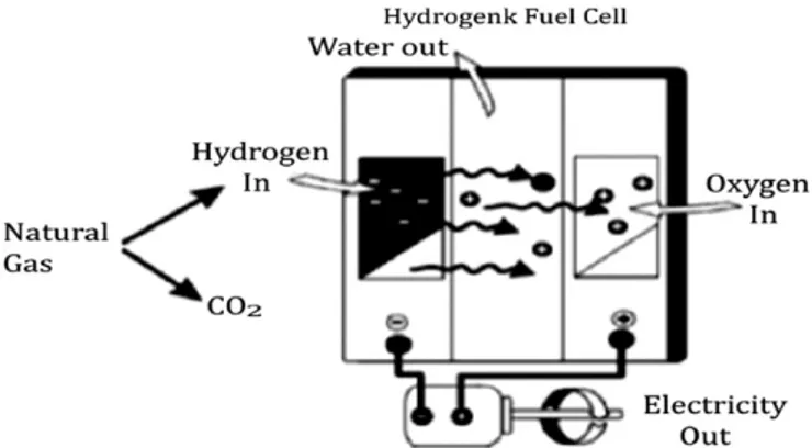
Nowadays, the majority of hydrogen produced worldwide is accomplished by steam methane reforming. The efficiency of steam reforming process is about 65–75% among the highest of current commercially available products[79]. Natural gas is the best method to produce hydrogen as it is convenient, easy to handle, and high hydrogen-to-carbon ratio.Fig. 15shows one of the hydrogen applications as reforming the natural gas. The hydrogen can be used in fuel cell in order to generate electricity.
3.2. Coal gasification
Through coal gasification with the addition of carbon capture technology, high volume stream of hydrogen can be produced. In gasification process, the mixing of pulverized coal with an oxidant, heated to about 18001C have a very hot synthesis (syngas). The syngas consists of hydrogen, carbon monoxide, carbon dioxide, other gases and particle. To remove the other gases and particle, the syngas is cooled and cleaning process is proceeded.
During the cleaning of syngas, any particulate such as mercury, sulphur, trace contaminants and foreign matter are removed. Then, the syngas reacts with steam by a process called water gas shift reaction to produce more hydrogen and carbon dioxide as final product as inFig. 16. The hydrogen then can be used as a vehicle fuel or to generate electricity for other purposes such as power plant and industry. Meanwhile, as carbon dioxide has also been produced at the end, a technology is needed to decrease or at least sustain the amount of carbon dioxide emissions in the atmosphere. Nowadays, carbon dioxide emissions can be reduced near to zero when applying carbon capture storage and seques-trations technologies [82,83]. By increasing the efficiency of operation in the gasification process, the pollutants can also be reduced significantly.
Carbon capture and storage concept is used for capturing and storing the carbon dioxide permanently that has been produced from coal gasification or any other industrial activity [84]. The carbon is stored naturally in the earth’s terrestrial biosphere (in forests, soil, and plants) and ocean reservoirs (via the ocean carbon cycle), from which it is cyclically released and absorbed
[82]. The percentage of carbon dioxide emissions to atmosphere can be reduced is about 90% by implementing the concept of carbon capture and storage in pulverized coal plant.
3.3. Electrolysis
Fossil fuel energy sources such as natural gas, coal and petroleum are not sustainable as these are depleting and there are severe damages to the environment because of the activities to produce hydrogen. In order to make a global sustainability and stability, renewable energy such as electrolysis and biomass gasification needs to be commercialized, and replaces the use of fossil fuel significantly[85].
To operate the electrolysis process, the electricity needed, can be generated either from fossil fuels or renewable energy such as solar power. In water electrolysis process, the hydrogen produced is clean, with high purity and is as simple as using electricity, generated by fossil fuels. Besides using electricity as the source, the hydrogen can also be produced by photo catalytic water splitting. This technology is still in experimental stage due to low efficiency and high cost [86]. At present, only about 5% of hydrogen in the world is produced by water electrolysis[87].
Currently, the best solution to the high cost of electrolysis process is by using sustainable sources such as solar, wind and or nuclear. In this paper, renewable energy as the source for electrolysis will be discussed. There are many types of electrolysis such as alkaline water electrolysis, polymer electrolyte membrane (PEM) electrolysis, solid oxide electrolysis, and photo-electrolysis
[87,88]. The difference among the electrolysis systems is the source of power to conduct the electrolysis, the constructions, conversion efficiency, and availability in industries.
Alkaline water electrolysis is one of the easiest methods for hydrogen production because of its simple construction. A basic water electrolysis unit consists of an anode, a cathode, power supply and an electrolyte[88]. The molecules of water (H2O) can
be split to form pure hydrogen and oxygen by using electricity. However, when the electricity used, is generated by burning fossil fuels, the pollutant emissions cannot be avoided. But producing hydrogen by using renewable energy source, the efficiency is around 68% [89]. For application in transportation sector, the electrolyzers, used in the electrolysis process, can be reduced in size to suit the fuel cell vehicles that give an important advantage in the development of FCV market.
Table 13shows the different electrolysers that can be used to produce hydrogen gas. The different electrolytes are used in
![Fig. 2. Hydrogen induction in spark-ignition engine [10].](https://thumb-eu.123doks.com/thumbv2/123dok_br/16423550.727540/3.892.161.750.87.429/fig-hydrogen-induction-in-spark-ignition-engine.webp)
![Fig. 3. Minimum ignition energies of ( K ) hydrogen–air, ( ’ ) methane–air and (m) heptane–air mixture in relation to at atmospheric pressure [18].](https://thumb-eu.123doks.com/thumbv2/123dok_br/16423550.727540/4.892.506.776.864.1085/minimum-ignition-energies-hydrogen-methane-relation-atmospheric-pressure.webp)
![Fig. 5. Typical variations in indicated power output and efficiency with changes in compression ratio when using optimum spark timing for borderline knock [33].](https://thumb-eu.123doks.com/thumbv2/123dok_br/16423550.727540/6.892.51.427.862.1080/typical-variations-indicated-efficiency-changes-compression-optimum-borderline.webp)
![Fig. 6. Analysis of losses compared to the theoretical engine cycle; gasoline versus hydrogen (PFI and DI), at two loads [12].](https://thumb-eu.123doks.com/thumbv2/123dok_br/16423550.727540/8.892.141.737.87.426/analysis-losses-compared-theoretical-engine-gasoline-versus-hydrogen.webp)
![Fig. 7. The total energy efficiency in percentage [63].](https://thumb-eu.123doks.com/thumbv2/123dok_br/16423550.727540/11.892.65.839.122.671/fig-total-energy-efficiency-percentage.webp)
![Fig. 12 shows the renewable energy life cycle to produce hydrogen [74]. From Fig. 11, the extraction from natural sources is fossil fuels](https://thumb-eu.123doks.com/thumbv2/123dok_br/16423550.727540/12.892.201.692.93.276/renewable-energy-produce-hydrogen-extraction-natural-sources-fossil.webp)
![Fig. 11. Production of gasoline and hydrogen from fossil fuel [74].](https://thumb-eu.123doks.com/thumbv2/123dok_br/16423550.727540/13.892.470.841.683.934/fig-production-gasoline-hydrogen-fossil-fuel.webp)
![Fig. 14. Greenhouse gases emitted by type of hydrogen production [74].](https://thumb-eu.123doks.com/thumbv2/123dok_br/16423550.727540/14.892.69.827.691.1118/fig-greenhouse-gases-emitted-type-hydrogen-production.webp)