Department of Information Science and Technology (DCTI)
IoT System for EV Charging at Shared Spaces
Jose Pedro Marques da Cruz de Sousa Martins
A Dissertation presented in partial fulfilment of the Requirements for the Degree of Master Computer Science Engineering
Supervisor:
PhD, Joao C Ferreira, Assistant Professor
ISCTE-IUL
i
Acknowledgements
It is hard to write a fair acknowledgment section, not by the lack of humbly, but by the general sense that all our achievements are due to the contribution of everyone with we have the benefit to interact and learn from, all the behaviours, all successes in where we were involved or observed, and in particular, as we learn by failing, all the failures that we experienced (which marks us) and all the failures that we learn from others.
While being influenced by all my previous live events and interactions, so I would need to thank everyone for allowing me to have this fantastic experience which is "learning", this journey, like every other journey, is strongly influenced by a smaller group of persons, that inspired to it, contributed to it, were affected for it, and sometimes without being allowed to choose, were “forced” to contribute. Those are persons to whom I would like to express my gratitude (taking the risk of missing some), without any particular order of importance.
To my small family, Sonia (wife) and kids (and dog), that living behind the same roof, contributed with reviews, critics and with their immense comprehension by the family activities and events missed, from the simple things like arriving to the dinner table (always) late, be absent in important activities (and sometimes forget them) and most of the times, although physically present, completely absent, lost in my thoughts, to them I need to thank for their patience and support. To my large family for their compression and firm support, although less involved, always present ready and available to help.
To my grandparents, in particular to my grandparent Rogério, that have been (and is, at the time of this writing) always present in all my life events, strongly influenced my personality and values, helped me follow my choices and objectives, supporting them in all possible ways, sometimes disagreeing (and advising against it) other times being negatively impacted by them, but always supporting them.
To all my previous employers and colleagues that, while working, allowed me to learn, to expand my knowledge, to tail my behaviour and allowed me to fail and helped to learn with it. A special thanks to everyone that, when joining the companies where I was working for, I (tried to) mentor and taught me, (boldly) challenging my beliefs.
To the ISCTE-IUL community from my colleagues with whom I paired in groups for working in course projects, to share and discuss ideas. To my professors (which I will not disclose the names as I may need to enumerate almost all), for the knowledge and experiences
shared, and mainly, for the inspiring behaviour and, in some cases, for the passion, enthusiasm, and energy transmitted while discussing a specific topic (genuinely inspiring).
Finally, I must express the most definite sense of gratitude, to my thesis coordinator, Professor João Carlos Ferreira, the achievements of this work are a direct consequence of his intense involvement, support and hardly would be reachable without his help. Apart from the coordination and guidance of the work, from the idea (conception) to its realization in the strict sense, Professor João has provided one incredible help, being present and available during the entire process, helping me to keep the focus, motivation, leading me to continue working towards the defined goals even when sometimes the demand on my professional activity started to push to the other direction. His inspiring and mentoring behaviour challenged me to progress further on my academic studies, and I am the most thankful for all the support closing this stage, for the inspiration to embrace a new challenge and help to continue further.
iii
Resumo
No presente trabalho, é aplicado um paradigma de Internet Of Things (IOT) para agilizar e controlar o processo de carregamento de Veículos Elétricos (VE) em espaços partilhados de menores dimensões, como por exemplo condomínios residenciais, sem que seja necessária a intervenção (a título de prestação de serviços) de uma entidade externa, sendo todo o processo controlado pela gestão de condomínio.
Uma aplicação móvel permite ao utilizador interagir com o sistema, permitindo a este autenticar-se no mesmo é condição necessária para que seja despoletado o processo de carregamento do VE. O sistema implementado com recurso a um microcontrolador encontra-se ligado a um conjunto de encontra-sensores e um atuador permitindo medir a energia que esta encontra-ser consumida para carregamento do VE e simultaneamente, ligar e desligar o dispositivo de carregamento do veículo (através do controlo de um interruptor que entrega a energia entregue a este). O processo é controlado por uma unidade de gestão centralizada, que gera a distribuição de energia pelas estações de carregamento de VEs de acordo com as limitações do condomínio através do ligar e desligar destas e em simultâneo regista e processas as medições da energia consumida para consolidar as informações que constituem a transação de carregamento de VE e respetiva contraparte financeira associada à mesma.
Adicionalmente, a unidade de gestão centralizada e a aplicação móvel, disponibilizam interfaces de utilizador mínimas para permitir funções como a consulta de transações, gestão e configuração da plataforma.
Complementarmente, é apresentado um modelo conceptual permitindo escalar a solução proposta para espaços partilhados de maior dimensão, com recurso à utilização de tecnologias
blockchain para gestão e registo das transações financeiras associadas à operação. Propondo
uma abordagem, que poderá ser replicável em cenários mais amplos de utilização como por exemplo, a infraestrutura publica de carregamento de VE de uma cidade.
O protótipo desenvolvido foi testado num espaço partilhado com três VE, usando uma infraestrutura de carregamento durante 3,5 meses.
Palavras-Chave: Veículos Elétricos, Carregamento de Veículos Elétricos, Blockchain, IoT, Aplicações Moveis.
Abstract
In current work, we apply the Internet of Things (IoT) paradigm to handle the electric vehicle (EV) charging process in small shared spaces, such as condominiums without requiring the intervention of an external supervision entity, being that role performed by the condominium management.
A Mobile App handles the user interaction with the system, authenticating the request to initiate the EV charging process, a microcontroller connected to set of sensors and an actuator is used for measuring energy consumption and for enabling the charging process and, a Management Unit controls the process end to end, providing the required services to the Mobile App and the microcontroller unit while manages the energy sharing between the EV charging stations accordingly the condominium limitations and processes the energy measures to consolidate the EV charging energy transaction. A minimal user interface allows the users to visualise transactions, manage users' preferences, and configure the platform.
Additionally, the conceptual model for a scaled solution is presented, supported on blockchain technologies to handle the financial transitions, allowing current approach to be replicated on broader EV charging scenarios, such as public charging systems in a city.
The developed system was tested in a shared space with three EVs using a charging infrastructure for 3.5 months.
v
Table of Contents
Chapter 1 – Introduction ... x
1.1. Context ... x
1.2. Motivation ... xi
1.3. Research Question and Work Objectives ... xi
1.4. Methodological Approach ... xii
1.5. Structure and Organization ... xii
1.6. Scientific Contribution ... xiii
Chapter 2 – State of Art ... 1
2.1. Power Limitations ... 1
2.2. Authentication ... 2
2.3. Blockchain ... 2
Chapter 3 – Proposed Approach & Conceptual Model ... 5
3.1. Problem Identification – Identification of Requirements ... 5
3.2. Conceptual Model ... 8
Chapter 4 – System Implementation ... 12
4.1. System Design ... 13
4.2. System Development ... 40
4.3. System Testing and Evaluation ... 44
4.4. System Deployment ... 49
Chapter 5 – Results at a Condo ... 51
Chapter 6 – Conceptual Model for EV Charging Stations Using IoT, Cloud, and Blockchain ... 56
6.1. Scaling Up ... 56
6.2. Blockchain / Cryptocurrency Integration ... 58
Chapter 7 – Conclusions and Further Work ... 61
7.1. Conclusions ... 61
7.2. Limitations ... 62
7.3. Future Work ... 63
Tables
Table 1.List of IoT hardware add-ons. ... 15 Table 2.Amperometric Clamp vs Sensor Reading ... 45 Table 3.Data collected during the case study. ... 51
vii
Figures
Figure 1.IoT System Architecture Reference Model (adapted). ... 5
Figure 2.Use case diagram of the Mobile App. ... 7
Figure 3.Use case diagram of the Management Application. ... 7
Figure 4.IoT Domain Model. ... 8
Figure 5.IoT Domain Model instantiation for the proposed solution. ... 9
Figure 6. Component architecture of the proposed EV charging platform: Server Application, IoT Units, and Mobile App. ... 11
Figure 7.Methodology for creating (IoT) system. ... 12
Figure 8.Overview of the proposed EV charging platform in shared spaces. ... 14
Figure 9.Hardware components used to build the IoT Unit for the proposed EV charging platform. ... 17
Figure 10. Non-Intrusive Sensor installed for calibration purposes. ... 19
Figure 11.Non-Intrusive Current and Temperature Humidity Sensor Wiring. ... 20
Figure 12.IoT Unit Lifecycle Activity Diagram ... 21
Figure 13.IoT Unit Initialise Activity Diagram ... 22
Figure 14.IoT Unit Work Cycle Activity Diagram. ... 24
Figure 15.Communication between the IoT Unit and Management Unit ... 25
Figure 16.Raspberry Pi Model 3+. ... 27
Figure 17.Software infrastructure and flows of information. ... 28
Figure 18.Self-generated API (to support interfacing with third-party applications). ... 30
Figure 19.SPA Architecture Diagram. ... 31
Figure 20.General software architecture pattern. ... 32
Figure 21.Management Unit services. ... 33
Figure 22.Mobile App functional and software architecture views. ... 35
Figure 23.MVVM Pattern Representation. ... 36
Figure 24.Communication between Mobile App and the Management Unit. ... 37
Figure 25.Mobile App User Registration. ... 38
Figure 26.Mobile App User Queue Charging Operation. ... 39
Figure 27. Implemented Prototype. ... 40
Figure 28.Mobile App screenshots. ... 41
Figure 29.Mobile App functionalities. ... 42
Figure 30.Mobile App interface for starting (a) and stop (b) the EV. ... 42
Figure 31.Web application: Users list (left) / Sensors list (right). ... 43
Figure 32. Calibration Process - Amperometric Clamp (14.63 A reading). ... 44
Figure 33.Sensor Calibration Data. ... 46
Figure 34.Management Unit Testing Strategy. ... 47
Figure 35.Setup diagram of the case study. ... 49
Figure 36.Developed prototypes. ... 50
Figure 37.Average charging power and charging duration during each charging event. ... 52
Figure 38.Simultaneous charging (during the test period). ... 52
Figure 39. Charging hours (Y-axis) per charging session event in 3.5 months for sensor 0, used to charge a Leaf with 24 kWh battery capacity. ... 53
Figure 40.Energy (kWh) per each EV charging session in a Leaf with 24 kWh battery capacity. ... 54
Figure 41. Charging windows (power limitation allows only two EVs to charge simultaneously). ... 54
Figure 42. Charging time (left) and energy (right). ... 55
Figure 44.Overview of an IoT/cloud model solution to handle the EV. ... 57 Figure 45.Blockchain interactions with an internal (local) ledger. ... 58 Figure 46.Blockchain interactions using an open cryptocurrency. ... 59
ix
Acronyms and Abbreviations
ADC – Analogic to Digital Converter BC – BlockChain
CS – Charging Station
DBMS – database management system
DSRM – Design Science Research Methodology
EEPROM – Electrically Erasable Programmable Read-Only Memory EV – Electric Vehicle
HTTP – HyperText Transfer Protocol
HTTPS – HyperText Transfer Protocol Secure IoT – Internet of Things
IoT ARM – IoT Architectural Reference Model IoT DM – IoT Domain Model
IP – Internet Protocol LAN – Local Area Network MVC – Model View Controller PKI – Public Key Infrastructure
REST – Representational State Transfer SPA – Single Page Application
SQL – Structured Query Language SOC – (EV’s) State of Charge TCP – Transfer Control Protocol UML – Unified Modeling Language URI – Uniform Request Locator WAN – Wide Area Network
Chapter 1 – Introduction
1.1.Context
One of the significant challenges related with electric vehicle (EV) market penetration is the charging process, where the main problems are associated with the lack of proper infrastructure in the existing residential buildings (condominiums) since they were not prepared to fulfil this new requirement.
Condominiums often have a problem with shared electricity, which fails to meet the EV owner’s requirements, another facet of this challenge is the associated with rental houses and the need for supporting EV charging during limited periods only, which due to elevated number for rental houses (‘Stat of the Week’, 2018) gives to this issue a new dimension.
In condominiums, unfortunately, there is a general reluctance regarding the installation of EV charging stations that will only be used by a few homeowners (‘Stat of the Week’, 2018). In addition, there is also an issue regarding the safety and limitations of the electrical installations, as they were not built upfront to support EV charging stations and, adapting the condominium electrical infrastructure will require that a consensus between the majority of the owners is reached, often hard to achieve, and eventually authorizations issued by the government building safety entities are also required.
Taking into consideration that most residential buildings have shared spaces with standard electrical installations, not prepared for the installation of new EV charging systems, this is considered a barrier to EV uptake (Axsen et al., 2015). A study by Lopez-Behar et al. (‘Putting electric vehicles on the map: A policy agenda for residential charging infrastructure in Canada’, 2019) identified four main problem domains in the context of sharing EV charging solutions in buildings:
• Unavailable charging infrastructure; • Building limitations;
• Regulation issues; • Parking availability.
xi 1.2. Motivation
Taking into consideration the issues exposed in the previous section, it urges to research, and evaluate the design of solutions that will allow to address the problems identified, aiming to contribute to the increase of adoption of the EV in the existing communities, as the replacement of the combustion vehicles by electric vehicles will increase the use of renewable energy sources reducing the environmental footprint.
The new advances in the Internet of Things (IoT) technologies (Al-Fuqaha, Guizani, Mohammadi, Aledhari, & Ayyash, 2015), associated sensing and acting devices, communication platforms and, information systems have the potential to create new solutions for the identified problems.
The presented problem and the (eventual) availability of technical means to solve it, lead us to the goal of this work, which is, to explore those new technologies and evaluate how can they be used to address and improve the stated problem.
1.3.Research Question and Work Objectives
Based on the exposed, the research performed on this work aims to devise an approach supported on the new IoT developments to solve the identified problems related to the EV charging in shared spaces.
It is the primary goal of this work to design and implement an IoT-based system for handling the EV charging process in a condominium, which can be used in the context of a shared energy infrastructure without requiring a formal supervision entity to control the process, to manage the EV charging processes accordingly the shared space power limitations, controlling the number of simultaneous EV charging.
To achieve this goal, an IoT System was developed, that connected to each power socket or charging device (i.e., between the power grid and the EV charging device), delivers energy only to an authenticated users, guaranteeing their identity and the non-repudiation of the associated energy transaction, while measuring the energy consumption to generate accounting or billing information, allowing each user to pay for their energy consumption.
1.4.Methodological Approach
The Design Science Research Methodology (DSRM), was followed as the methodological approach for developing this work.
Design Science (DS), is defined as the study of artificial, targeting the creation of new and innovative artefacts (Simon, 2008). The Design Science Research Methodology (DSRM) aims to systematise the application of the Design Science Research through the definition of an iterative Process Model composed by the sequence of steps or activities presented below (Peffers, Tuunanen, Rothenberger, & Chatterjee, 2007):
• Problem Identification and Motivation; • Define Objectives for a Solution; • Design and Development;
• Demonstration; • Evaluation; • Communication.
Aiming to document the current work using a standard graphical notation, the Unified Modeling Language (UML) is used due to its high acceptance under the development community (Fowler, 2004).
1.5.Structure and Organization
This document, structured in seven chapters, is organised as follows:
• Chapter 1 (the current chapter), introduces the current work, focuses context, motivation, and sets the objectives to be achieved.
• Chapter 2 presents the state of the art in related works.
• Chapter 3 describes the approach followed and introduced a conceptual model and establishes its mapping with the IoT Reference Model and Architecture (Bauer, Boussard, et al., 2013; Bauer, Bui, et al., 2013).
• Chapter 4 describes the System implementation flow. • Chapter 5 presents a case study at a condominium.
• Chapter 6 elaborates a conceptual model for extending the current work to Charging Stations using IoT and Blockchain.
• Chapter 7 closes the document, presenting the conclusions, and discusses future implications of the presented work.
xiii 1.6.Scientific Contribution
The work developed supported the writing of the following article for a Special Issue of the Journal Energies (ISSN 1996-1073), published in this Q1 journal in 2 of august 2019:
Martins, J. P., Ferreira, J. C., Monteiro, V., Afonso, J. A., & Afonso, J. L. (2019). IoT and Blockchain Paradigms for EV Charging System. Energies, 12(15), 2987. DOI:10.3390/en12152987
Chapter 2 – State of Art
The proposed approach explores a set of works in several domain areas to create a new approach to handle the EV charging process in shared spaces, including the use of IoT sensing devices to measure electricity consumed on the EV charging process and coordinate the power distribution between the EV charging nodes of the shared space, accordingly the shared space power limitation.
As EV charging payment process is more frequent than fossil fuel refuelling and more complicated due to the immaturity of the service, issues related to the following points are relatively common:
• Transparency and clarity of rates and costs before they are incurred;
• Ability to pick-and-choose best rates and location of available charging points on
the go;
• Ability to request priority charging and pay for it, when other EVs do not need priority;
• Ability to select a supplier or source of electricity, which would also enable greater competition and increase the trust of customers;
• Preferences for various types of payment, such as post-paid, pre-paid, or one-off payment.
This work complements previous works on an EV charging systems (Joao C. Ferreira, Monteiro, Afonso, & Silva, 2011; Joao Carlos Ferreira, da Silva, & Afonso, 2011) and IoT energy measurements using local sensors on (J. Ferreira, Afonso, Monteiro, & Afonso, 2018) while focusing new challenges for the energy markets discussed in (J. Ferreira & Martins, 2018). Together with mobile device authentication, local sensors, and a management unit, we developed a new approach applicable to shared EV charging spaces.
Another exciting output is to use of mobile devices to provide authentication and payment services in the context of the public EV charging systems, exploring recent advances in mobile device payment systems for public transportation (Baia, Ferreira, Filipe, & Cunha, 2013) and other application areas (Dahlberg, Guo, & Ondrus, 2015).
2.1.Power Limitations
Concerning driver profiles and EV charging with power limitations, several studies have been performed, and we apply a simple approach inspired on a previous work described in (J.
2
C. Ferreira, Monteiro, & Afonso, 2014). Another issue originated by the increase of the EV charging needs is the impact on the energy demands and the power limitation of the existing infrastructure (C. Liu, Chai, Zhang, Lau, & Chen, 2018), which may not only increase the operational costs to fulfil the required demand but also affects the voltage stability of the network. In (C. Liu et al., 2018), the authors introduced the AdBEV, which is an algorithm to optimise the EV charging schedule, maximising the voltage stability at the power grid side, and minimising the charging costs.
2.2.Authentication
In our implementation, it was also considered an implicit authentication mechanism (Bo, Zhang, Li, Huang, & Wang, 2013), applied on user’s mobile devices requests to the Management Unit, which confirms the user authentication based on actions that he had performed previously in a daily basis. This implicit authentication mechanism can be used to prevent fraudulent transactions on a mobile device, verifying that the user is who claims to be during the transaction. After researching systems that meet our criteria, we found some promising works (De Luca, Hang, Brudy, Lindner, & Hussmann, 2012; Feng et al., 2012; Jakobsson, Shi, Golle, & Chow, 2009; Patel, Chellappa, Chandra, & Barbello, 2016; Sae-Bae, Ahmed, Isbister, & Memon, 2012), and we also found a solution targeting the user privacy (no identification is performed) in an approach based on the system proposed called Touchalytics (Frank, Biedert, Ma, Martinovic, & Song, 2013).
2.3.Blockchain
Complementing the work performed, we present a conceptual model to apply a blockchain-based approach to handle distributed transactions without central supervision. The application of blockchain in the domain of smart grids has excellent potential, providing a decentralised approach to implement management systems (Pop et al., 2019) and handle energy transactions. The primary goal of the blockchain is to allow decentralised transactions using a digital currency, such as Bitcoin (Nakamoto, 2008) or Etherum (‘A Next-Generation Smart Contract and Decentralized Application Platform’, 2014/2019), without the need of a public authority to control the process. From the technical perspective, a blockchain is as a record database composed by a sequence of linked blocks (similar to table rows on the relational model), where the transactional information, each block, is linked to the previous block and cryptographically signed (Panarello, Tapas, Merlino, Longo, & Puliafito, 2018).
From the functional perspective, the User A performs a transaction, links the transaction to the previous block and cryptographically signs the block with his private key, and, the new block is sent to all the nodes of the network, being the synchronization and authenticity of each block guaranteed by a consensus protocol between the participating nodes. To verify the integrity of a received block, the User B checks the cryptographic transaction signature using the public key of user A. This process has the following properties:
• Decentralisation, the new block is sent to the network to validation and certification, without the intervention of a central authority.
• Anonymity, since it allows for the authentication of transactions without giving up any personal information (B only needs to know A public key);
• Auditability, which is guaranteed based on the fact that each of the transactions is recorded and validated with a timestamp, where users can trace the previous transactions by accessing any node in the distributed network.
The meter sampling information has the potential to use a considerable amount of data, in particular as all the blocks are sent to all the participants on the network. Aiming to minimise the amount of information stored on the chain, (Pop et al., 2019) presents a design to balance the amount of information kept on-chain/off-chain while keeping the properties of blockchain implementation. The authors of (Erdin et al., 2018) suggest that the use of an open public cryptocurrency network, such as Bitcoin or Ethereum, can introduce a high transactional costs, due to the fees associated with cryptocurrency transaction processing (eventually similar to the cost of the energy supplied), and propose the development of a private Bitcoin-based blockchain network for EV charging purposes. Other relevant application cases include micro-generation (J. Ferreira & Martins, 2018; Sanseverino, Silvestre, Gallo, Zizzo, & Ippolito, 2017), as well as the contribution to handle the EV charging payment process without the use of propriety company payment systems.
Some issues identified are also addressed in (Pustisek, Kos, & Sedlar, 2016), which proposes a blockchain-based model with recourse to a bid to identify charging stations (and eventually schedule the charging), complementary to the approach suggested in (Joao C. Ferreira et al., 2011). In (Thakur & Breslin, 2018) the application of a blockchain-based process is suggested to support the EV charging queue management.
As a new topic of research, new publications are appearing in the literature concerning the use of a blockchain approach to handling the EV charging process, such as:
4
• Testing pilots to use digital currency for the EV charging process (Higgins, 2016; ‘RWE and Slock.it – Electric cars using Ethereum wallets can recharge by
induction at traffic lights’, 2016);
• A proposal of a P2P energy transaction model to handle the EV vehicle-to-grid (V2G) operation in smart grids (Kang et al., 2017);
• Handling the EV authentication issues based on a blockchain approach (Garg, Kaur, Kaddoum, Gagnon, & Rodrigues, 2019);
• Proposal of a cross-domain authentication scheme with blockchain (D. Liu et al., 2018);
• Handling of security and privacy issues for energy transactions based on blockchain.
Moreover, in this context, the EV is identified as part of the energy market (Aitzhan & Svetinovic, 2018), a contribution to the contextualization of the local energy market is presented on (Mengelkamp, Notheisen, Beer, Dauer, & Weinhardt, 2018), where the blockchain plays an essential role in the decentralization process, as well as for optimization purposes (Munsing, Mather, & Moura, 2017).
Chapter 3 – Proposed Approach & Conceptual Model
The current section aims to identify the requirements for the proposed system, derived from the objectives presented in the previous section and presents the conceptual model accordingly the IoT System Architecture Reference Model introduced in (Bauer, Boussard, et al., 2013; Bauer, Bui, et al., 2013). Figure 1 presents the components of the architecture model used to describe the conceptual model of the system addressed in section 3.2.
Figure 1.IoT System Architecture Reference Model (adapted).1
3.1.Problem Identification – Identification of Requirements
The following requirements were identified based on the initial problem: 3.1.1.Real-Time Energy Metering
A metering device must be easily attachable to the existing devices EV charging devices (between the EV charging device and the power socket) and able to measure and register the energy delivered to the charging EV, the during the charging process. As the energy delivery is a continuous measure, the instantaneous current must be periodically sampled (the discretisation process will introduce a measurement error in the inversely proportional to the sampling frequency).
6 3.1.2.Manage the energy power limitations
Due to the power limitations of a condominium and aiming to avoid changes in their power infrastructure to increase its capability, allowing to charge several EVs simultaneously, with incurred costs on the adaptation of the existing infrastructure and an eventual increase in the cost of the energy as often the energy pricing is calculated by the energy consumed and also by the available power, the system must be able to manage the number of simultaneous charging EVs.
3.1.3.Secure Identify / Authenticate the charging EV
As the energy transaction will have a financial impact as the EV owner is responsible by supporting that cost, the system must guarantee the identification of the user requesting to charge the EV, to avoid the repudiation of the transaction.
3.1.4.Account and Report Energy Transactions
The system must be able to gather all the measurements, to allow a fair distribution of the energy costs, into a consolidated energy transaction and, associate each energy transaction to a specific EV owner, providing usage reports to allow the correct accounting of the energy spent.
3.1.5.Reduced Implementation Costs
In particular, inside a condominium, the fair division of these costs by the benefiting members can be complex to achieve and, frequently, a consensus must reach to allow the approval of any changes that will incur in costs to the condominium. Devising a solution with reduced or absent of changes in the energy infrastructure is a crucial factor to the acceptance. The following design options can contribute to this objective:
• Self-Contained
The solution should be complete, self-contained, and able to explore the existing infrastructure, to ease the deployment inside a condominium.
Changes in the energy distribution infrastructure of a building may require an entire project to be put in place, with the required legal approvals, project plans, inspection, and validation by certifying bodies, which can have a high cost. The devised approach should require minimal or none changes to the existing infrastructures.
Figure 2 and Figure 3 presents the Use Case diagrams (Fowler, 2004) for the actors participating in the system.
Figure 2.Use case diagram of the Mobile App.
8 3.2.Conceptual Model
The IoT ARM (Bauer, Boussard, et al., 2013) proposes a model to conceptually present the architecture of an IoT independent of the used technology, whereas the IoT Reference Model (Bauer, Bui, et al., 2013) sets the stage for the IoT ARM, defining a set of concepts and relations on the IoT Domain Model. Figure 4 exposes a UML representation of the IoT Domain Model.
Figure 4.IoT Domain Model2.
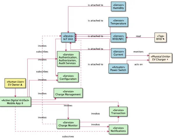
Figure 5 presents the instantiation of the EV Charging platform using the IoT DM.
Figure 5.IoT Domain Model instantiation for the proposed solution.
Following the approach suggested by Figure 1, the developed EV Charging platform can be decomposed and organised into several functional perspectives. The IoT ARM suggests the existence of an intermediate layer between the Network/Communication and the Application Layers to include all the supporting activities required to enable the information flows between those layers, however, for the current exposition, and due to the limited scope of the developed system that intermediate layer was not taken into consideration. This layered functional segregation, identifies each existing sub-system abstraction, allowing to consider the entire IoT system as a composition of several building blocks, which can be replaceable independently, providing high flexibility to the developed system.
Follows the mapping the components of the developed IoT system, some identified on the domain model, in Figure 5, into the layers proposed in Figure 1.
10
Is considered that all the IoT Unit components are on the Device Layer, respectively the IoT Unit and the sensors and actuators attached to it, the current, temperature, humidity and, RFID sensors as well as the power switch that acts on the EV Charger, switching it on/off;
• Network Layer
The model suggests that all components required to exchange information between the Device Layer and Application Layer should be organised and identified in this layer. On the developed system, the network components attached to the IoT Unit, to Management Unit and, even the Mobile Device networking capabilities, should be considered, even if physically connected to a specific element:
• Application Layer
On the Application Layer, we can consider the services or components Charge Management, Charge Monitor, Transaction, Notification Services, as well as the Mobile App, as all these components are accountable for providing the IoT system functionality and core for performing that activity;
• Management Layer
Are considered elements of this transversal layer, the components that contribute to the management of the platform, from the instantiation of the IoT Charging EV Platform on the IoT Domain model, on Figure 5, we can identify the Configuration service and eventually some components of the Authentication, Authorization and Auditing services. In the IoT ARM model, we can find at this layer, the elements related to Configuration, Fault, Reporting, Membership, and State functional activities;
• Security Layer
This layer integrates all the security-related activities, from our instantiation, Authentication and, Authorization services, as well as some components (not identified in the domain model) like the HTTPS engine, belong to this transversal layer, from the model it can also be identified, Key Exchange and Management, Trust & Reputation, and Identity Management.
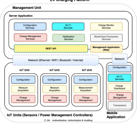
To summarise, the EV charging platform is composed of the elements presented in Figure 6, whose roles are briefly described below, whereas the details for each component are addressed in the next section:
• IoT Unit. Sensor and Power management units that support the interaction with the EV charger, used to enable or disable it (on/off switch), to measure the amount of power consumed, gather environment temperature and humidity (complementary measures), and to upload all the information to the Management Unit;
• Mobile App. The element that establishes the interaction between the EV owner and the platform authenticates the user, starts/stops the charging process, and provides some everyday operations, such as configuration management, usage dashboards, transactions lists;
• Management Unit. Controller heart of the platform, provides all the backend services to support the required operations, orchestrating the IoT units to deliver energy, accordingly the limitations. It also implements the management console for the platform. In the developed prototype, aiming to keep the solution self-contained, it also acts a physical network element, configured as a Wi-Fi access point, providing network access to the IoT units and the Mobile App, but it could also be implemented using a cloud computing platform.
Figure 6. Component architecture of the proposed EV charging platform: Server Application, IoT Units, and Mobile App.
12
Chapter 4 – System Implementation
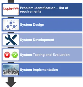
The system development followed a standard SDLC flow, Figure 7 displays the phases considered, described below, except for the Problem Identification, which previously addressed in section 3.1.
4.1.System Design
Following the model presented in the previous chapter, the proposed EV charging, platform is composed of three significant elements, detailed in the current section:
• IoT Unit;
• Management Unit; • Mobile App.
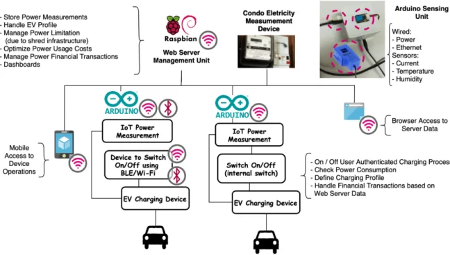
Figure 8 shows an overview of a condominium with the proposed EV charging platform, the significant characteristics for the proposed system are:
• Mobile App, to allow the EV owners to interact with the platform, authenticate on the platform, manage user’s preferences, monitor charging process and energy transactions;
• IoT Unit, based on Arduino Microprocessor, to control the energy release and collect the delivered energy measures and transmit the required information to the Management Unit;
• Management Unit, based on Raspberry PI configured as a WiFi network access point, and while acting as controller of all the system, store system data, handling energy transactions and financial counterparty and managing the charging according to the power limitations available on the infrastructure.
The following features can be highlighted:
• A pre-registration with a local EV charging providers is not required, avoiding the problem of different cards in different charging infrastructures (every charging infrastructure has its cards, and this is a problem for EV owners because they need several charging cards when different providers are available);
• Reduced costs (almost zero fees), because there is no requirement for a third-party central management entity, apart from the condominium to management, which would create additional costs;
14
• No infrastructural changes as the system manage the energy distribution accordingly the power limitations of the installation.
4.1.1.IoT Unit
Hardware
The IoT unit was developed following the initial approach described in work presented in (J. Ferreira & Martins, 2018). The re-assessment of the surrounding environment, context, overall requirements, conducted to the refinement of the initial architecture into a flexible system architecture able to support different network transmission requirements/devices, current sensor devices, and power switching devices, tailoring their combination to match a specific installation requirement, targeting a commercial level system prototype.
After an initial period of checking and testing hardware, the solution implemented was based on an Arduino Uno (microcontroller) combined with the devices listed in Table 1, where only one component for each type was used to assemble the IoT unit.
Table 1.List of IoT hardware add-ons.
Component Type Device
Network (Shields) Sparkfun ESP8266 (Wi-Fi) WIZnet's W5100 (Ethernet) Current Sensors SCT-013-000 (non-intrusive)
ACS712 20A (intrusive)
Power Switching (*) SRD-05VDC-SL-C (generic network switch) Temperature and Humidity DHT11
NFC RFID (**) Wireless Module PN532
(*) The Management Unit can control a generic network-controlled switch. Approaches such as BLE-controlled switches can eventually also be used, providing that the IoT unit included a BLE Add-On
(**) Near Field Communication and Radio-Frequency Identification
The most relevant characteristics of the hardware components used for the prototype implementation are:
• Arduino R3 Uno Microcontroller (Figure 9a), based on the microcontroller ATmega328P, it has the following characteristics (from the Arduino R3 Uno dataset);
o 14 Digital Input/Output pins
§ Two for serial RX/TX (Receive and Transmit)
§ Six with pulse-width modulation (PWM) output capability to mimic an analogue output
16 o 16 MHZ clock speed
o Memory: Flash, 32 K; SRAM, 2 K; EEPROM, 1 K o USB type B connection, ICSP Header
o Power input 9 V (operating voltage 5 V), built-in LED, reset button
• Sparkfun Wi-Fi Arduino Shield, based on ESP8266 (Figure 9b), manufactured by Sparkfun, used to connect the Arduino microcontroller to a Wi-Fi network and using the “standard” internet protocols (TCP or UDP);
• Arduino Ethernet Shield, based on Wiznet W5100 (Figure 9c), used to connect the Arduino microcontroller to an Ethernet network using the “standard” internet protocols. Compliant with the IEEE 802.3 10Base-T and 802.3u 1000Base-TX standards, includes a TCP/IP hardwired stack, supporting up to four simultaneous connections and a transfer rate up to 100Mbps;
• Non-Intrusive Current Sensor SCT-013-000 (Figure 9d), a non-intrusive sensor used to measure the current passing through a conductor without the need to cut or modify the conductor itself. The measurements are collected from the electromagnetic induction, which is proportional to the intensity of the current passing through the conductor. This sensor collects measurements up to 100 A, outputting at 50 mA, with an accuracy of 1% to 2% of the actual value;
• Intrusive Current Sensor 20 A, based on ACS712 (Figure 9e), based on ACS712 this intrusive Hall effect current sensor can be used to measure currents between -20 A and +20 A, with an output ratio of 100 mV/A;
• Power Switch 10 A, based on SRD-05VDC-SL-C (Figure 9f), a mechanical relay which operates a switch. With a control line (+5 V) that when powered, establishes a connection between the terminals Common (C) and Normally Open (NO). The used part also includes a small LED which is enabled when the circuit between the terminals C and NO is established. An SLA-05VDC-SL-C based switch can replace the selected actuator to support impedances up to 30A;
• Temperature and Humidity Sensor, based on DHT11 (Figure 9g), from DFRobot, can work from 0 to 50 °C and humidity from 20% to 90%, and has low power consumption, with a precision of 2 °C;
• RFID/NFC Reader/Writer, based on PN532 (Figure 9h), has several wireless capabilities, it can be used to read and write RFID and to exchange data with Near Field Communication (NFC) enabled devices.
(a) Arduino R3 Uno
Microcontroller (b) Sparkfun Wi-Fi Arduino Shield, based on ESP8266 (c) Arduino Ethernet Shield, based on W5100
(d) Non-Intrusive Current Sensors,
SCT-013-000 100A (e) (d) Intrusive Current Sensors, based on ACS712 (20A) (f) Power Switch, based on SRD-05VDC-SL-C.
(g) Temperature and Humidity
Sensor, based on DHT11 (h) PN532 based, Near Field Connection (NFC) (i) Configuration DIP Switches and Reset Button Figure 9.Hardware components used to build the IoT Unit for the proposed EV charging platform.
18
Configuration Options
Follows the brief comparison of the different device types that can be combined tailoring the system to a specific installation requirement.
Ethernet (Wired) / Wi-Fi (Wireless)
Most existing condominiums do not have a wired network infrastructure, based on that assumption, the use of a Wi-Fi network simplifies the deployment of the system, as no other infrastructure components are required, mainly when using the Wi-Fi network provided by the Management Unit. Newer installations or installations with specific topologies/environments with a weak Wi-Fi signal propagation (e.g., multiple floors) a cable-based network approach may be more suitable and less error-prone.
Intrusive / Non-Intrusive
The non-intrusive sensor, SCT-013-000 100A, (Figure 9d) offers the capability to measure the energy that passed through a specific IoT unit, allowing the measures to be gathered without any changes to the existing infrastructure, as the sensor only needs to be “hooked” around one of the wires of the power cable that powers the EV charger device socket. Since the system acts only as a passive observer, measuring the current that flows to the EV as no physical devices are installed between the power plug and the EV charging device, the capability to enable/disable the charging process needs to be implemented by the EV or by the charging station, exposed as a service to the charging platform. This service-oriented approach, to switch on / off the energy delivery (using standard network protocols or other communication technologies, like BLE), introduces a dependency to an external system (eventually hard to manage due to the lack of standards for this purpose). On the other hand, the intrusive approach forces the platform owner to introduce the IoT device between the power grid and the power socket, which requires some intervention in the existing infrastructure, but it is able to provide a sound solution to the platform owner, as it provides a “one-in-a-box” unit that is able to measure and control the energy delivery (enabling/disabling) simultaneously, while providing energy only to authenticated users.
Built-In vs COTS (Commercial-Off-The-Shelf) Power Switching
To enable/disable the EV charging devices, we have considered using the SRD-05VDC-SL-C (Ningo Song relay Co, Zhejiang, China) device (see Figure 9f), which, when connected to the Arduino device, can be used as a switch (the SLA-05VDC-SL-C must be used to support a current up to 30A). A different approach to support this requirement is to use a standard
TCP(Cerf & Kahn, 1974)/IP-based (Transmission Control Protocol - Internet Protocol) switch commonly available as COTS on the market.
IoT Unit Wiring
The SCT-013-000 100A current sensor (Figure 9d) is as a current transformer. The sensor is placed around the power cable (Figure 10), and on the sensor terminals, a fraction of the current that is flowing through the power cable can be measured.
Figure 10. Non-Intrusive Sensor installed for calibration purposes.
Arduino (Figure 9a) has 5 Analogic I/O Ports (A0-A5), accepting a voltage between 0V and 5V, connected to a built-in Analogic to Digital Converter, which translates analogic value to a digital value between 0 and 1024. The current on the sensor’s terminals must be transformed into voltage so that information can properly be processed. Several references are found online (Caballero, 2016; ‘Learn | OpenEnergyMonitor’, 2018; ‘SCT-013-030 Energy Meter’, 2016, p.). Figure 11 presents the components used to connect the current sensor the Arduino microcontroller as well as the connections between the components.
20
(a) Breadboard. (b) Schematics.
Application Software
The software implemented in the Arduino Uno microcontroller was developed in C++ through the Arduino IDE and Microsoft Visual Studio Code. Figure 12 displays the high-level activity diagram for the IoT Unit, which can be organised into the initialisation and work cycle functional blocks. The communication with the server to obtain the configuration and sending of readings is done using the TCP (Cerf & Kahn, 1974) and HTTP (Fielding & Reschke, 2014) protocols, using the GET and POST methods.
Figure 12.IoT Unit Lifecycle Activity Diagram
Figure 13 presents the sequence of activities executed on the bootstrap of the IoT Unit, that can be described as follows. As soon the IoT Unit is started it checks if the reset configuration button is pressed (Figure 9i) and in that case, the configuration stored on the EEPROM is erased, and the IoT unit is restarted.
After the previous step, the configuration is loaded from the EEPROM, and their checksum and expiration date are validated. If the configuration is absent or invalid, the device contacts the Management Unit in a well-known address to obtain the initialisation configuration data, receiving the unit configuration parameters (e.g., unit identification, network configuration, servers address, sampling rate, etc.). Two approaches can be used to identify the IoT Unit sending the request to the Management Unit. If the configuration is invalid or absent, the sensor id is read from the IoT unit dip switches (Figure 9i), a total of 64 (26) IoT units can
be configured to obtain configuration data from the Management Unit, otherwise if the configuration is expired, the configured sensor id, stored in the EEPROM is used. After fetching the configuration data from the Management Unit and storing the configuration on the EEPROM, the unit is restarted.
22
Assuming that the IoT unit has a valid configuration, the network interface is initialised, and the IoT unit fetches the clock time from the Management Unit. A standard network time protocol like NTP (Mills, Delaware, J. Martin, & Burbank, 2010) could be used, but it would require the IoT unit to be able to reach the internet and access to well-known NTP server, adding a dependency to an external system, which could be mitigated by upgrading the Management Unit to provide that services increasing the load on the Management Unit. Additionally, the use of the standard internet time protocol NTP, as it relies on the UDP (Postel, 1980) protocol, a connectionless protocol from the IP stack, would increase the implementation complexity on the IoT Unit (which has limited resources).
At this stage, the unit enters in the standard operation mode, presented in Figure 14 and discussed below.
Figure 13.IoT Unit Initialise Activity Diagram
Figure 14 shows the standard main loop executed by the IoT unit, following the previous approach, follows a brief description of the process. The primary process of the IoT
Unit consists of an infinite loop (until the unit is restarted or powered off) in, for each cycle iteration, several activities are executed. To provide a reasonable reactivity to the RFID/NFC reader and simultaneously avoid flooding the Management Unit with a high number of sensor readings, the main loop has a time period (every 10 secs, by default) shorter than the time period used by the IoT unit to sync with the Management Unit and send the sensor reading (every 1 minute, by default).
On the beginning of each iteration the IoT unit checks for the availability of RFID/NFC data (if an RFID/NFC was attached to the unit) and, if data is available the unit forwards the information to the Management Unit. The outcome of the operation is not being presented to the user, and nevertheless, as a future extension, it could be used to provide some feedback to the authenticating user related to the operation. If the Management Unit successfully processed an RFID/NFC reading or if the amount of time between the last sync with the Management Unit, the IoT Unit reads the inputs from the sensors (Temperature, Humidity, and Current) and sends that information to the Management Unit, which as an outcome of the operation returns status information and operations to be executed by the IoT Unit. If the unit fails to send the information to the Management Unit, it will retry the request for a specific number of attempts and reboot the unit if the maximum number of attempts is reached (which will switch off the energy delivery).
24
Communication with Management Unit
Figure 15 presents a sequence diagram for the communication flows between the IoT Unit and the Management Unit, as well as the surrounding associated processing. Since the IoT Unit has reduced computing resources, the information is exchanged using a character-oriented protocol, sharing information either on the request URI or on the message payload.
26 4.1.2.Management Unit
The Management Unit coordinates and orchestrates the IoT Units connected to the platform. This section is divided into the following subsections: Hardware; Software Infrastructure; Application Software and Services Infrastructure; Management Services; Management Web Application.
Hardware
The Management Unit was built using a Raspberry Pi 3 Model B+ hardware (Figure 16), and the Raspbian operating system.
The unit was configured as a Wi-Fi access point, setting up the network to allow Wi-Fi communications between all the platform components (Management Unit, IoT units, and Mobile Devices / App).
This configuration allows the deployment of a completely self-contained, pluggable, low-cost solution, without requiring any other infrastructure components (apart from the energy power grid), while increasing the security of the overall solution by reducing its exposure to external network threats.
Complementarily, if deployed in a location with existing network support, the Management Unit can be connected to the network using the RJ45 Ethernet connector of the Raspberry Pi, allowing the platform to benefit from the existing infrastructure and to eventually be deployed in setups where the use of a Wi-Fi network may not be available or the most suitable option, for instance, a multi-level condominium parking lot, or a parking lot spread over several areas and sharing only one Management Unit.
The Raspberry Pi 3 Model B+ is the final revision in the Raspberry Pi 3 family, the most relevant characteristics, extracted from the component technical specification are:
• Broadcom BCM2837B0, Cortex-A53 (ARMv8) 64-bit SoC @ 1.4GHz • 1GB LPDDR2 SDRAM
• 2.4 GHz and 5GHz IEEE 802.11.b/g/n/ac wireless LAN, Bluetooth 4.2, BLE • Gigabit Ethernet over USB 2.0 (maximum throughput of 300 Mbps)
• One extended 40-pin GPIO header • Full-size HDMI
• 4 USB 2.0 ports
• DSI display port for connecting a Raspberry Pi touchscreen display • 4-pole stereo output and composite video port
• Micro SD port for loading the operating system and storing data • 5V/2.5A DC power input
• Power-over-Ethernet (PoE) support (requires separate PoE HAT)
28
Software Infrastructure
Figure 17 displays the software infrastructure components required to implement the Management Unit platform elements (IoT unit, Mobile App ). The primary role of each component will be described in the current section.
Figure 17.Software infrastructure and flows of information.
From the software perspective, the Management Unit uses as Operating System the Raspbian, which is a Linux, Debian based operating system built and optimized to run on the Raspberry PI, configured as a WiFi Access Point (‘Setting up a Raspberry Pi as a Wireless Access Point—Raspberry Pi Documentation’, 2019) to provide WiFi network access to the Mobile Application and to the IoT Units. The Management Unit relies on the following infrastructure software/services:
• File System
As being one of the core services provided by the operating system, apart from the
standard use, in the context of the current application, the file system is used directly
as static storage (storing the static contents to be served by the webserver) and as a storage unit for archiving the platform logs;
• MariaDB
Relational Database Management System (DBMS), serves as the primary location to store all the information managed by the platform;
• NGINX (HTTP/HTTPS)
Web server routes the requests received on the standard HTTP(80)/HTTPS(443) ports to the services endpoints exposed internally inside of the Management Unit, acting as a proxy between the “external world” and the services layer. It also serves all the static contents requests (the Management Unit administration is a single web page application that consumes the services exposed by the service layer). Aiming to guarantee the security of the communications between the Management Unit and the Mobile App, all the services exposed to the Mobile App use a secure channel (HTTPS protocol). The use of the HTTPS protocol requires a digital certificate to encrypt the communications. Although a self-signed certificate can be used, aiming to avoid communication errors, a trusted certificate, freely provided by Let’s Encrypt, was installed;
• EV Charger Platform (Spring/SpringBoot Framework)
The platform services, built using the Spring Framework and SpringBoot, are exposed by the framework as a set of Representational State Transfer (REST) endpoints. Exposing an API (Application Programming Interface) in a standard language, that can be easily used by third-party applications, using interoperability tools available on the market, allowing the development of custom-made integrations (for instance, to integrate the platform with a condominium management system);
• Swagger Framework
Aiming to document the service APIs exposed, the Swagger Framework was integrated into the EV Charger Platform, to generate the services documentation automatically. Figure 18 displays a screenshot of the self-generated documentation.
30
Figure 18.Self-generated API (to support interfacing with third-party applications).
• Web Application
The Management Unit implements a browser-oriented web interface for management purposes. This web interface, implemented using the Angular Framework, uses a single page application architecture, consisting in a set of static files served by NGINX web server to the client browser, which invokes the services provided by the EV Charger Platform.
Figure 19.SPA Architecture Diagram.
Although all the infrastructure server software is being deployed directly on the top of the operating system, a container-based approach (for instance, Docker (Ismail et al., 2015)) can also be applied to remove all the dependencies of the between the hardware/operating system and infrastructure/applicational software, encapsulating all the infrastructure and applicational software in a completely self-contained box (container), that can be deployed in other operating systems or hardware platforms.
32
Applicational Software
The applicational software, following a simple responsibility principle (SRP) (Martin & Martin, 2018) is composed by a set of services of modules, exposed with the SpringBoot container, as a set of Representational State Transfer (REST) endpoints. The services are implemented, following a similar layering pattern, presented in Figure 20, where each layer have specific roles:
• Service Layer: Acts as a mapping service, translating the external representation of the information to the internal representation;
• Business Layer: All the application behaviour is defined in this layer, and any interaction between layers made exclusively through the interface provided at this level;
• Persistence Layer: This layer maps the internal representation of the information to the representation used by the database engine.
Figure 21 presents the application level services or modules that constitute the EV charging platform, the description of the implemented services, and their contribution to the overall platform is presented in the current section.
Figure 21.Management Unit services.
• Configuration: Provides a set of services required to configure the EV platform, allowing the user to define several platform parameters, such as the existing sensors and their configuration (e.g., network configuration, maximum current, accounting frequency, measure period), as well as the groups of sensors (e.g., sensors inside the same group, maximum load per group);
• 3A (Authentication, Authorization, Auditing): This module has a central role in the entire platform. It is responsible for centralising all the operations related to user/system authentication (“who is who “), authorisation (“what can do”) and auditing (“what was done”). Apart from implementing the set of operations to manage the user access to the platform, it also implements the implicit authentication (J. C. Ferreira et al., 2014) to validate the charging request automatically, based on the current user’s usage pattern;
• Charge Monitor: This module collects and processes all information generated from the installed sensors to update the EV charging records and detect the end of the charging events, as well as any anomalies on the charging process (e.g., exceeding the nominal current, temperature, charging time), and triggering eventual notifications when required. This module also collects the user’s usage pattern to estimate the power needs for the current charging process, as well as estimate the
34
leave time of the EV from the charging plug, if that information is not provided explicitly by the user;
• Charge Management: If the installation has the capability to enable or disable the EV charging process, by the use of network-controlled charging devices or by the use of charging switches attached to the sensor unit, the module enables or disables the charging of the EV, aiming to properly distribute the available charging windows between all the EVs connected to the charging group, based on the charging requirements and the amount of time that the vehicle will be connected to the charging device and using the information provided explicitly by the user or inferred by the platform based on the users usage pattern;
• Notification Services: This module provides all the notification related services to the platform, routing the system-generated notifications to users that had subscribed to that notification (i.e., vehicle charged, abnormal charge pattern, etc.);
• Transaction: This module supports all the “financial” related operations, aggregating the information related to the charging operations providing reporting capabilities to allow the financial management and analysis of the platform usage. In a blockchain integrated approach (presented only as conceptual model), this module should also be responsible by recording the changing events in the blockchain ledger, allow the platform managers to transfer “charging tokens” to the user’s wallet (if not using an open public crypto-currency network), monitor the reception of user’s transferred credit to start the charging process and return the unused credit to the user’s wallet.
4.1.3.Mobile Platform
Hardware
No specific hardware requirements were identified for a mobile device running the Mobile App as it acts as a consumer of the services exposed by the Management Unit, apart from being able to connect to a network where the Management Unit is reachable.
Software
Aiming to allow the EV owners to use the platform, a Mobile App was developed in C#, using a development platform and framework Visual Studio and Xamarin.Forms, respectively. The choice to use a multiplatform development platform allows developing software for several platforms simultaneously (Android, iOS, and UWP), minimising the number of changes between platforms.
Figure 22 presents the software architecture pattern used and functional organisation of the Mobile App.
(*) 3A—Authentication, Authorization and Auditing Figure 22.Mobile App functional and software architecture views.
From a functional perspective, the Mobile App is split into several modules enforcing the separation of concerns between each functional component. On the software architecture perspective, as the Mobile App is mainly a client or a frontend for the services provided by the Management Unit, it is implemented following a straightforward application of the Model-View-ViewModel (MVVM) pattern, an extension of the Presentation Model (PM) pattern (‘Presentation Model’, 2004), frequently used in Xamarin.Forms applications and other
36
software platforms. On software architectural pattern, each logical layer has a clear separation of concerns, briefly described below, and graphically presented in Figure 23:
• View
Implemented with XAML (eXtensible Application Markup Language), a declarative language used to design and structure the user interface.
• View-Model
Layer that intermediates the relationship between the View and the Model, binding the information and actions between the model components.
• Model
Representation of the application data.
Figure 23.MVVM Pattern Representation3.
To store data locally (configuration) and to establish communication with the Management Unit, two other components are considered:
• REST Adapter
As the Mobile App relies on services provided by the Management Unit, this component acts as a proxy between both entities;
• Local Storage
Small information repository managed by the Mobile App to store configuration data in the mobile device.
Communication with Management Unit
Figure 24 presents a sequence diagram for the communication flows between the IoT Unit and the Management Unit. The information exchanged between the Mobile App, and the Management Unit uses the HTTPS protocol (Rescorla, 2000), relying upon digital certificate installed on the server, to securely transfer information by encrypting the exchanged messages. Aiming to the benefit of the authentication and authorisation services provided by the Spring Framework, the standard HTTP (Fielding & Reschke, 2014) authentication headers are communicated inside this secure channel. Stronger authentication schemes could be supported by the use of client certificates at the webserver level (NGINX) to authenticate the Mobile App requests on the server; however, this was not considered for the current implementation to avoid the complexity of introducing a Public Key Infrastructure (PKI) in a platform relying in a Raspbery PI.
38
Initiating the Charging Process.
Despite all the communication between the Mobile App and the Management Unit be secured with the use of an HTTPS certificate installed on the Management Unit, that authentication scheme only guarantees the authentication of server platform, in this case, the Management Unit. Aiming to achieve that non-repudiation of the charging request, due to it’s financial relevance and, avoiding to rely exclusively in a user/password security scheme, which only guarantees that the Mobile App user, knows the user credentials for a specific user, a signing scheme was implemented to secure the queue (start) charging operation. For this purpose at the user registration instant, a private/public key is generated on the mobile device, being only the public key shared with the Management Unit, Figure 25 presents the registration flow using a UML sequence diagram.
Figure 26 presents a sequence diagram from starting (or queuing) charging operation. When requesting the EV Charging, the request is signed by the user using it’s private key and sent to the Management Unit, which validates the signature of the message against the user’s public key, stores the operation request message as it establishes a binding contract between the user and mobile device and the charging platform and, queues or starts the charing operation if the power being used is below the shared space power limitation.
40 4.2.System Development
The current section presents some of the developments achieved during this project. 4.2.1.IoT Unit
Figure 27 presents one developed prototype, with the following components: • Configuration dip switches and resets button;
• Arduino board;
• Ethernet Arduino shield; • Power switch;
• Temperature sensor; • Plug to the current sensor; • Current sensor (Figure 27b).
(a) IoT Unit (b) Current Sensor
4.2.2.Mobile App
Apart from the EV charging process, which can be considered the crux of the system, the Mobile App also implements several features that, although not as relevant, are required to achieve a production-grade design stage. Figure 28 and Figure 29 shows screenshots for some of the implemented features:
• Application splash screen, Figure 28a and Current usage pattern, Figure 28b; • Application settings, Figure 28c, and Energy costs calculated based on kWh and
statistical sensor measures, Figure 29a; • List of sensor readings received, Figure 29b;
• Sensor configuration details, Figure 29c and About screen, Figure 29d.
(a) Splash-screen (b) Current Graphics (c) Application Settings Figure 28.Mobile App screenshots.
(a) Calculated Power Costs