Int. J. Vehicle of Design, Vol. 24, No. 4, 2000 372
Thermal behaviour simulation of the passenger
compartment of vehicles
E.Z.E. Conceiqao*, Professor M.C.G. da
Silvat, J.C.S. Andre and D.X. Viegast
*UCEH, Universidade d o Algarve, Portugal.1-DEM-FCT, Universidade d e Coimbra, 3030 Coimbra, Portugal. Abstract: In this work a calculus program developed with the objective of simulating the thermal behaviour in the passenger compartment of vehicles is presented. The model is based on the space-integral energy balance equations for the inside air and for the main vehicle body and surfaces. It can solve two kinds of problems. In the first one, it calculates the heat stress that the air conditioning system must equilibrate in order to satisfy predefined permanent regimen project specifications. In the second one, once imposed a particular air conditioning system and given the ambient conditions, it computes the different temperatures and heat fluxes, either in transient or steady regimens. The validation of this model was done with a railway car, in a summer situation, when it was immobilized and running. The model reproduced well the experimentally determined temperature and heat flux evolutions. However, the numeric simulation showed best agreement with the experimental results when used with the convection heat transfer coefficients, determined experimentally in this work.
Keywords: convection heat transfer coefficients, heat balance equation, radiative properties of glass, simulation program, solar irradiation, vehicle project.
Reference to this paper should be made as follows: Concei@o, E.Z.E., Silva, M.C.G., AndrC, J.C.S. and Viegas, D.X. (2000) 'Thermal behaviour simulation of the passenger compartment of vehicles', Int. J. of Vehicle Design , Vol. 24, NO. 4, pp.372-387.
Nomenclature
Complete symbols
%Pt Atmospheric turbidity parameters
D m
Inclination angle, relative to the horizontal, of a plane surface s[o] Solar declination angle of the day of the yearAx[ml Glass thickness
EC Correlation factor
4
["I Local latitudeThermal behaviour simulation of the passenger compartment of vehicles 373 G y
[Ol
Yveh ["I Ke w l lN
- N u n ror1
0 [Ole,[O1
Ra Re RH[%] o [W m-2 K - ~ ] t[sl Tatm ~ s[OC] k ~ ~ [ W r n - ~"c-'1
vi[m3 h-'1 Vveh[m 5'1WI
a m 1 Main symbols Nm21 a z [ w m 2 OC-'] C[J "C-'1 W m I E h[J Kg-'] I[W m - 2 ~ K [ w ~ - ' "C-'1 Grashof numberAzimuth angle of a plane surface Vehicle orientation in relation to the south Radiation extinction coefficient of glass Total number of slices in the body vehicle
Mean convective heat transfer coefficient on a surface Refraction index of an glass-air interface
Radiative incident angle Radiation incidence angle Zenith angle
Rayleigh number Reynolds number Air relative humidity
Stefan-Boltzmann constant (5.67 x Real solar time
Atmosphere transmittance coefficient
Black body equivalent radiation temperature of the nocturnal sky Mean heat transfer coefficient by conduction between two slices Flow rate of air circulation in the passenger compartment Vehicle driving speed
Inclination angle, relative to the vertical, of a plate surface Height above sea level.
Surface area
Radiation absorption coefficient
Mean convective heat transfer coefficient on a surface Total heat capacity of a body
Slice thickness
Radiating emissivity of a surface Specific enthalpy
Solar irradiation on a surface Thermal conductivity of a slice
374 E.Z.E. ConceipZo, M. C. G. Silva, J. C.S. Andre' and D.X. Viegas K ~ [ W ~ - ~ " C - ~ ]
m
[kg S-I1
QPI
V0C1 T Sub-indexes air B surv
Super-indexes b d downTotal heat transfer coefficient Mass rate
Total heat flux Temperature
Glass transmittance coefficient
Relative to the surface adjacent air
Relative to the vehicle body: left panel (1); right panel (r) and ceiling panel (c)
Relative to directional radiation
Internal vehicle bodies (seats, floor, driving instruments pane) Relative to diffuse (more or less isotropic) radiation
External air
Relative to the vehicle glasses: right (r); left (1); front (f) and back (b) Air inside the vehicle passenger compartment
Vehicle luggage compartment Vehicle motor compartment Relative to a horizontal plane surface Vehicle passengers
Vehicle heating and/or air conditioning system Relative to the plate surface in convection Air renovation
Relative to directional radiation
Relative to diffuse (more or less isotropic) radiation Relative to the plate down surface
Vehicle external face of a surface Vehicle internal face of a surface Relative to the plate up surface Time derivative
Thermal behaviour simulation of the passenger compartment of vehicles 375
1 Introduction
People spend an important part of their time in transportation. So, it is very important that the vehicles have a passenger compartment with a good environment, which does not disturb people but gives them comfortable conditions during travelling time.
The problem of providing a good indoor climate in vehicles is a difficult one because the external conditions change over time, the asymmetries are very strong, the occupation rate per surface unit is quite large and the glazed area is very important.
The study and development of new ventilation or air conditioning systems for vehicles are usually conducted by experimental means, because the problem is very complicated to solve numerically, resulting in the resolution of coupled heat transfer and fluid flow equations in an irregular geometry. However, during the project phase, some important guidelines can be provided by simple simulation computational models, thus reducing the time-consuming experimental tests to a minimum.
2 Physical and mathematical model
2.1
IntroductionThe model here presented is based on that of Shimizu et al. (1983), with some improvements concerning the computation of solar radiation heat loads, the inclusion of a nocturnal heat balance, the division of the vehicle ceiling and side panels composite plates in various slices and the incorporation of a sub-model to the determination of the convection heat transfer coefficients.
The main goal of the model is to predict the air temperature in the passenger compartment, either in steady or transient conditions. It can also be used to obtain the heat load that the vehicle heating and air conditioning units must supply to keep a previously specified temperature inside the vehicle, under nominal steady ambient conditions.
The main body of equations of the model expresses a space-integral heat balance for the air inside the vehicle passenger compartment and for the air inside the vehicle passenger compartment and for the group surfaces that confine it, namely: the ceiling, the side panels (doors), the glasses and the interior bodies (seats, floor, driving instruments panel), etc.
The basic hypothesis used to write out the former balances are the following: non- uniformities in the temperature distribution throughout each body are neglected; convective and conductive heat fluxes are treated as unidimensional. Additionally, special hypothesis will appear along the exposition. Also, for brevity reasons, the properties definition is done in the nomenclature section. The heat balance equations are always written with the sensible heat storing term in the left member and the heat flux terms in the right one.
2.2
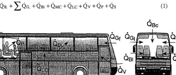
Main heat balance equations of the modelThe heat balance equation of the air inside the vehicle passenger compartment is as follows (see also Figure 1):
376 E.Z.E. Conceigiio, M. C. G. Silva, J. C.S. Andre' and D.X. Viegas
Figure 1 Definition of the heat loads on the air inside the vehicle passenger compartment. In the former equation the air is supposed to be transparent to radiation, so, all the heat flux terms have a conductive and/or convective character. These terms are written as positive if they drive heat in, according to the following equations:
QBj =
E $ A ~ ,
(T%-
Ti)(j-
r , l and c)Ti represents in all the equations the temperature of the air inside the passenger compartment. In Equations 2 and 3, TBj is associated with the mean temperature of the vehicle body internal slice, TGj represents the glass mean temperature. In Equations 4-6, the other temperatures correspond, respectively, to the surface of the internal bodies (mainly the seats), the air inside the motor and the air inside the luggage compartments. The heat flux
Q ~ ,
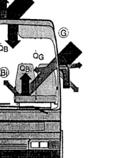
is used only when there is air renewal. In Equation 1, the heat load due to the passengers Q p , is computed along with the method developed by Fanger (1972), where one typical person releases approximately 115 W. Finally, the remaining heat flux in Equation 1, Q ~ , is due to the heating and/or air conditioning unit.In Figure 2, three kinds of the heat fluxes in the vehicle compartment are shown, namely to a vehicle body (B), to a glass (G) and to an internal vehicle body (Bi).
The vehicle body surfaces, left and right panel and ceiling, are divided in various slices, with each one associated with one component. This division is important to predict the thermal stratification along the wall.
The heat balance equation for the vehicle body is divided in three parts.
Thermal behaviour simulation of the passenger compartment of vehicles 377
Figure 2 Scheme of the three kinds of heat flux in the vehicle compartment.
where the super-index is associated to the slice number, being 1 the internal slice. The heat balance equation for a central slice of the vehicle body wall is:
where NBj represents the total number of slices in the body. The total heat transfer between two slices is determined by:
Finally, the heat balance equation for an external slice of the vehicle body is:
The coefficient cp takes the value 0 during the day and 1 during the night. The nocturnal sky is supposed to constitute a black body envelope at an effective temperature
378 E.Z. E. ConceipTo, M. C.
G.
Silva, J. C.S. Andre' and D.X. ViegasTsky, that may range from 4 3 "C to 12 "C, depending on the cloud cover (Incropera and DeWitt (1991)l. Nevertheless, Chiou (1986) considers that the outdoor temperature is a good estimate of the sky nocturnal temperature.
The set of equations expressing the heat balance for the glasses is:
-&)AG,(TG, -
T ~ )
- QG,(j=
r , 1, f and b)The last heat balance equation concerns the interior bodies in the passenger compartment, mainly the seats, and takes the following form:
C B ~ T * ~ = f a ~ i
[c(
t& b, IGj ( b )+
tGj IGj ( d ) ) A ~ , ] - Q B ~ ( j I 1, f and b)2.3
Solar irradiation
An auxiliary model is used to compute the evolution of the solar radiation during the simulation time. Its final outputs are the total solar irradiation on an arbitrarily inclined plane surface, I , divided in its beam ( i b ) and diffuse ( i d ) components. The set of empirical models adopted were taken from Iqbal (1983), and so will only be briefly described in this Section.
To determine the total irradiation on a horizontal surface, ( i b ) , the first process that is taken into consideration is the non-dissipative attenuation of radiation with the distance between the Sun and the Earth surfaces. This gives place to an extraterrestrial normal irradiation,
I?),
that would arrive at the Earth's surface if there was no atmosphere:I?) = Ec(day of the year) 1sc (14)
The second step consists in projecting the normal irradiation on a horizontal plane, to compute the extra-terrestrial irradiation on the horizontal surface:
where 0, = 0 , ( ~ , 6 , hour of the day)) and the conditions: 0, = oo,+9o0 define, respectively, the local solar hours of noon, sunrise and sunset.
The third step deals with the interaction of the extraterrestrial solar radiation beam with matter particles at its first passage through the Earth's atmosphere. This process, known as radiation scatter, is for two main effects. The first one is the attenuation of the transmitted beam, and can be computed as follows:
The second effect of radiation scattering is a certain isotropization of the initial perfectly directional beam, giving origin to a diffuse component of radiation, that can be written as:
Thermal behaviour simulation of the passenger compartment of vehicles 379
where the super-indexes stand for total scatter (s), Rayleigh-scatter (s,R) and Mie-scatter (s,M).
The fourth step incorporates the effect of multiple reflections at the Earth and top atmosphere surfaces, of the first passage beam and diffuse radiation components, (la. ,I:?). The additional radiation component that results from the former process, and
which has a diffuse nature, is designated as 15;).
As a synthesis of the former four steps, concerning solar irradiation on horizontal surfaces, it can be written:
The more general case of irradiation on an arbitrarily inclined plane surface, which orientation can be defined through a pair of angles (y,
P),
will now be treated. First, to compute the beam component of radiation, 1b1, from it,., it suffices to change the projection direction from the local vertical direction to the inclined plane normal direction, or, in symbols:Secondly, to estimate the diffuse component of radiation that incides on an inclined plane, two additional effects must be accounted for. The first consists in computing the fraction of the total diffuse component of radiation impinging on the horizontal surface, Id., that effectively reaches the inclined plane and it will be denoted here as sky diffuse radiation, 1 p ) . The second concerns the calculation of a new diffuse radiation component, denoted by I F ) , coming from the direct reflection on the ground of beam and diffuse radiation components
(iba
, i d m ) . An isotropic model is used to perform this calculation.In synthesis, the solar irradiation on an inclined plane has a beam component given by Equation 20 and diffuse and total components given by:
2.4
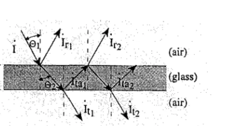
Radiative properties of the glassIn this Section, the sub-model used to calculate the directional and diffuse radiation absorption and transmission coefficients of a glass is summarily presented, following Duffie and Beckman (1980). In Figure 3, some notation is introduced and the relevant processes that radiation suffers in its passage through the glass are shown.
380 E. Z. E. Concei@io, 114. C. G. Silva, J. C.S. Andre' and D. X. Viegas
Figure 3 Directional radiation path traversing a finite thickness glass.
The directional properties are dealt with first. Incident solar radiation, I, may be decomposed along the normal and any parallel direction to the plane defined by the interface normal and the incidence direction, respectively, by I~ and I=.
Now, after Fresnel, each of the former radiation components has its own reflection coefficient at the glass-air interface that depends on the beam incidence angle 0,, and on the interface refractive index, n,, through the following expressions:
where the refraction angle, 0 2 , can be determined from Snell's law: sin(@
)
02 = arc sin
[?)
As a consequence, the total transmission, ( T ~ , T = ) , and absorption, ( a l , a = ) , coefficients of a glass with thickness Ax, for the two polarization components, ( I ~ , I = ) , turn out to be:
where 7, is the transmissivity of the glass for one passage of the radiation beam, that may
be computed from Bouguer's law as follows:
The coefficients given by Equations 26 to 29 take into consideration the successive reflections and absorptions along the radiation path in the glass (see Figure 3).
Finally, the correspondent total coefficients of transmission and absorption are given by:
T o calculate the correspondent properties for diffuse radiation, (zd,ad), it is simply assumed that it is isotropic, and so:
Thermal behaviour simulation of the passenger compartment of vehicles 38 1
2.5
Mathematical solution of the model
The whole set of the model's equations, presented in preceding Sections, permits the resolution of two main problems, each one admitting steady and unsteady variants. From the mathematical standpoint, the application of the model may give rise to three types of problems: linear and non-linear equation systems solving and the integration of first order ordinary differential equation systems coupled with a linear (non-linear) equation.
Linear equation systems are efficiently solved with the direct method of Gauss- Jordan with an optimal pivot searching. Optionally, this first solution can be refined through some iterations of a modified Gauss-Jordan algorithm, developed by Hildebrand (1956).
Finally, the integration of first order ordinary differential equation systems coupled with one linear equation, is performed with a fourth-order explicit Runge-Kutta algorithm. More details about the resolution of this equation's system are presented in Conceiqao (1996).
3
Numerical model validation
The case of a railway car was used to validate the present computational model. Tests were done in two typical summer situations; with the vehicle parked in a railway station and running.
The studied passenger compartment, 2.8 m high, 3 m wide and 23 m long, is isolated from the outdoor ambient in the longitudinal section, by the driver compartment and other passenger compartments. The considered railway does not have a motor compartment and the luggage compartment, considered in Figure 1, is substituted by outdoor air.
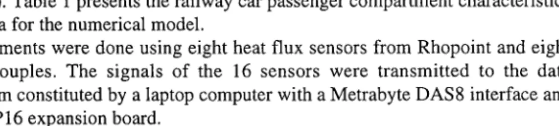
The lateral panels are divided into three slices (50 mm of glass wool, 2.2 mm of rubber and 2.3 mm of stainless steel) and the ceiling in six slices (1.5 mm of aluminium, 30 mm of glass wool, 350 mm of air, 50 mm of glass wool, 2.5 mm of rubber and 1 mm of stainless steel). Table 1 presents the railway car passenger compartment characteristics used as input data for the numerical model.
The measurements were done using eight heat flux sensors from Rhopoint and eight K-type thermocouples. The signals of the 16 sensors were transmitted to the data acquisition system constituted by a laptop computer with a Metrabyte DAS8 interface and a Metrabyte EXP16 expansion board.
Table 1 Input data for the numerical model.
Area [m2] Area [m2]
Floor 3 x 23 (KtLC = 0.79 w/m2 K) Ceiling 3 x 23 (aB = 0.37) Lateral colourless 0.86 x 18.14 (AX = 8 mm;
:
= 2.5') Lateral panels 0.72 x 23 (aB = 0.37) glassesInterior bodies 74 seats (CBi = 962000 JIK; a ~ i = 0.53; f = 0.75)
382 E.Z.E. Conceipio, M. C. G. Silva, J. C.S. Andre' and D.X. Viegas
The validation phase was divided into four parts; in the first one, the convection heat transfer coefficients were determined for this particular situation; the second part consisted in the solar irradiation routine validation and, in the third and fourth parts, the experimental tests for the railway car immobilized and running at a fixed speed after parking are presented, as well as the respective numerical simulation.
3.1
Experimental determination of convection heat transfer coeficientsThe convection heat transfer coefficients presented in the specialized bibliography are only related to isolated surfaces, varying from geometry to geometry. As, in the present case, the geometry was quite complicated, the convection heat transfer coefficients in the real vehicle passenger compartment were determined.
The measurements of the natural convection (inside and outside the passenger compartment) and mixed convection (inside the passenger compartment), were carried out in a full-scale laboratory section module of a passenger compartment, similar to that of the railway car. The module, placed in the laboratory, is 2 m long and has two rows of seats.
In Tables 2 and 3, the empirical correlations experimentally determined for the natural and mixed convection are presented. In the mixed convection, the air motion was caused by the air conditioning system installed in the laboratory module.
For the natural and mixed convection situations, the experimentally determined Nusselt number mean values are higher than determined by the empirical expression presented in the specialized bibliography. However, the empirical expressions determined in this work must be used only for situations similar to the present study.
Finally, the forced convection expression for the vehicle outside surface was determined in a real railway car and is the following:
-
Nu = 0.456 ~ e ~ . ~ ~ (33)
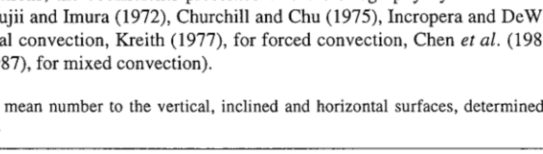
In some situations, the coefficients presented in the bibliography by some authors were used (see Fujii and Imura (1972), Churchill and Chu (1975), Incropera and DeWith (1990), for natural convection, Kreith (1977), for forced convection, Chen et al. (1986), Armaly et al. (1987), for mixed convection).
Table 2 Nusselt mean number to the vertical, inclined and horizontal surfaces, determined in natural convection.
Surface
-
Nu Correlation Application limitVertical 92.04 Ra0.09 0.69 3 . 5 9 ~ 109<Ra<4.37 x 1 01° Inclined (T~OYD > T.~) 8.35 (Ra cost<)0.179 0.93 1.5 x 1 os<Ra<l .6 x 1
o9
Inclined (T::~>
T i r ) 7.04 ~ a ~ 0.85 . ~ 4.7 x ~ 1 09<Ra<4.21 ~ x 1 01° Horizontal (T:$ > T.,) 23.12 ~ a ~ 0.75 . ~ 2.89 ~x 1 08<Ra<1.36 ~ x 1o9
Thermal behaviour simulation of the passenger compartment of vehicles 383
Table 3 Nusselt mean number to the vertical, inclined and horizontal surfaces, determined in
mixed convection.
Surface - Nu Correlation Application limit
Vertical 0.89 Re
0.52 <
-
< 2.2(Tsu~ < Tair) 0.555 Ra1'4[l+6.26(-&)]
45
Horizontal 0.90 1.5<*<3.2
(TF"
>air)
0.27 ~ a[
1+4.30 " ~($1
-45
Horizontal 0.89 Re 0.40 < - < 1.2(eWn
<% )
0.15 RalA[1+3.34($r]4s
Inclined 0.99 0.40<%<3.1 ( T W n i ) 0 . 5 6 ( R a c o ~ ~ ~ ' ~ [ l + l l . 5 8 ( ~ ~ ~ ]JGr
JGr
Inclined 0.99 Re 0.12 < < 0.90 (T: :: ">
~ , . ; 5 = 8') 0.56 ( ~ a cos5)
3.2
Solar irradiationIn Figure 4, a comparison between the solar radiation model predictions and experimental data is shown. The atmosphere's turbidity parameters
(a,
= 0.8,P, = 0.1), were not measured but simply fitted within the normal intervals for them, taking into consideration the relative clarity of the atmosphere on the day considered. Test took place in Coimbra (Z = 140 m, $ = 40.2", RH, = 56%) in the 9th of March. The other parameters used in the model are presented in Iqbal (1983).3.3
Stationary situationIn this test, the railway car was parked for a long time in the blazing sun. The test was done in Lisbon (2 = 40 m, (J = 39", RH, = 40%,y,,, = 16") on 28 April 1994. During
the test the sky remained almost clear, the railway car windows were closed and the curtains used for solar radiation protection were up. The experimental data acquisition rate of the temperature and heat flux was 1 sample per minute. The initial values, used in the numeric model, were determined experimentally.
384 E.Z.E. Conceipio, M. C. G. Silva, J. C.S. Andre' and D.X. Viegas
t (hours)
Figure 4 Comparison between the model's prediction (lines) and experimental data (points) for solar irradiation on a horizontal surface.
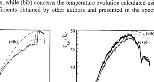
Figure 5a shows the comparison between the measured (thin line) and calculated (interrupted line) values of the air temperature inside the passenger compartment. In this Figure, (exp) represents the temperature evolution determined by the experimental heat transfer coefficients, while (bib) concerns the temperature evolution calculated using the heat transfer coefficients obtained by other authors and presented in the specialized bibliography.
- - 11 12 13 14 15 16 17
I
18 UX11 12 13 14 15 16 17 18a) t (hours) b)
t (hours)
Figure 5 Comparison of measured and calculated values of the air temperature (a) and right glass temperature (b).
The comparison between measured and calculated values of the right glass temperature is presented in Figure 5b. The outside and inside surface temperatures, determined using the experimentally (exp) and bibliography (bib) coefficients is presented. Figure 6b shows the temperature stratification in the six slices of the railway car ceiling, determined using the experimental coefficients.
.paluasa~d an slua!cnj~ao:, la js um way [epmwnadxa ayl 8y sn pau!uualap slInsal uoqnIoAa amle~adwa] ayl 'sam%d asayl UI .L Ia ~y ad sa l 'sarpoq lopalu! ay] lo j pue 8u ya 3 le:, Lempel aql 103 'sse18 @ !I aql l oj 'luau1lledwo3 la8uassed le3 de mp a spy! amleladwal 1 1" 103 SanpA pa]e~nqm pue pamseaw uaamlaq uospdwo:, ayl moys 8 pue L s al ns g 'y I 0009 = A Pue M LLI I = 'Q 'M S I I x 9 = do '% O~ = ' l3 3 '~183 S6.I= ZU 'S P ESI
-
SE (% p~ uo 1 aunf 66 pue ~ 1sal ayl alam suoglpuo:, :SMOIIOJ se qaA,t) = sp ', A~ qa =a
~
x
'! 6~ = q5 'm o~ = Z) uo qs q u ! auop sem lsal s ry ~ 'uo walsds Ire pa3103 ayl q l!m paads paxg e le unl sem le3 L em p aql <uns Bu~ze~q ayl u! po~lad Lauopeis 8uo1 e la lj v386 E.Z.E. Conceip70, M. C. G. Silva, J. C.S. Andrt and D.X. Viegas
22
12 12.29 12.57 12.86 13.15 12
u
12.29 12.57 12.86 13.15a) t (hours) b) t (hours)
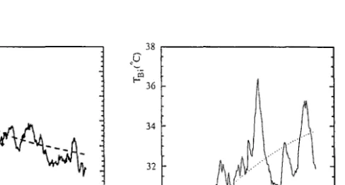
Figure 7 Comparison of measured and calculated values of the air temperature (a) and right glass
temperature (b).
a) t (hours) b) t (hours)
Figure 8 Comparison of measured and calculated values of the ceiling temperature (a) and
interior body temperature (b).
The experimental data of all the Figures present a certain parallelism: when the vehicle velocity decreases the temperature value increase and vice versa. Figures 7b and 8a show that the outside and inside surface temperatures have a similar evolution. In other words, when one increases the other increases too, and vice versa. This phenomenon is due to the important heat transfer through the railway car body.
The former Figures show that the numerical model stimulates better the thermal behaviour of the immobilized railway car than the one of a running railway car. This is due to the fact that the latter test situation is much more difficult to reproduce. The velocity was not constant on account of the motion of other trains on the same railway and the solar radiation in the external surface has fluctuations due, not only to the building shading, but also to the presence of some clouds in the sky.
Thermal behaviour simulation of the passenger compartment of vehicles 387
4
Conclusions
A computational model, developed with the objective of simulating the thermal behaviour of passenger vehicle compartments, is presented. S o m e experimental tests were done to validate the numeric model and the most important conclusions are the following:
the convection coefficients determined experimentally, for the natural and mixing convection, are slightly higher than the coefficients presented by other authors; this numerical model i s able to reproduce the passenger compartment thermal behaviour when this i s immobilized o r running;
the numerical model can be used to simulate the vehicle thermal behaviour and can provide an important contribution during the project phase of the vehicle.
Acknowledgements
T h e authors are grateful to the Companhia Portuguesa d e Caminhos d e Ferro (CP) and the first author gratefully acknowledges a grant from the Junta Nacional d e InvestigaqBo Cientifica e Tecnol6gica.
References
Armaly, B.F., Chen, T.S. and Ramachandran, N. (1987) 'Correlations for laminar mixed convections on vertical, inclined and horizontal flat plates with uniform surface heat flux',
International Journal of Heat and Mass Transfer, Vol. 30, No. 2, pp.405408.
Chen, T.S., Armaly, B.F. and Ramachandran, N. (1986) 'Correlation for laminar mixed convection flows on vertical, inclined and horizontal flat plates', Transactions of the ASME, Journul of Heat Transfer, Vol. 108, November, pp.385-840.
Chiou, J.P. (1986) 'Application of solar-powered ventilator in automobiles', SAE, International Congress and Exposition, Detroit, Michigan, February 1986, pp.13-22.
Churchill, S.W. and Chu, H.H.S. (1975) 'Correlating equations for laminar and turbulent free convection from a vertical plate', International Journal of Heat and Mass Transfer, Vol. 18, pp.1323-29
Concei@o, E.Z.E. (1996) Estudo Aero-TCrmico do Comportamento TCrmico de Veiculos de Transporte de passageiros, Ph. D. Thesis in conclusion phase.
Duffie, J.A. and Beckman, W.A. (1980) Solar Engineering of Thermal Processes, New York, John Wiley & Sons.
Fanger, P.O. (1972) Thermal Comfort, Technical Press.
Fujii, T. and Imura, H. (1972) 'Natural-convection heat transfer from a plate with arbitrary inclination', International Journal of Heat and Mass Transfer, Vol. 15, pp.755-766.
Hildebrand, F.B. (1956) Introduction to Numerical Analysis, McGraw-Hill Book Company, Inc. Incropera, F.P. and De-Witt, D.P. (1990) Fundamentals of Heat and Mass Transfer, New York,
John Wiley & Sons.
Iqbal, M. (1983) An Introduction to Solar Radiation, Academic Press.
Kreith, F. (1997) Principios da Transmiss50 de Calor, S5o Paulo, Brasil, Editora Edgard Bliicher Ltda.
Shimizu, S., Hara, H. and Azakawa, F. (1983) 'Analysis on air-conditioning heat load of a passenger vehicle', International Journal of Vehicle Design, Vol. 4, No. 3, pp.292-311.