IEEE Proof
Web Version
Compact Tapered Slot UWB Antenna
With WLAN Band Rejection
Carla R. Medeiros, Jorge R. Costa, Member, IEEE, and Carlos A. Fernandes, Senior Member, IEEE
Abstract—This letter extends the design of a previously
pro-posed uniplanar ultrawideband (UWB) antenna to include within its 3.1–10.6-GHz operation band a rejection of the wireless local area network (WLAN) band near 5.5 GHz. The antenna config-uration is based on a combination of two crossed exponentially tapered slots plus a star-shaped slot printed on both sides of a 10-mils dielectric substrate. The band rejection is obtained with the addition of extra slots at the antenna back-face metallization. The radiation pattern and polarization are very stable over the entire UWB. Link measurements between two identical antennas demonstrate low pulse distortion over almost all the solid angle.
Index Terms—Printed broadband antenna, tapered slot
an-tenna, ultrawideband (UWB) antennas, wireless local area network (WLAN) band rejection.
I. INTRODUCTION
U
LTRAWIDEBAND (UWB) radio is an emerging and promising technology for short-range applications en-abling extremely high data rate. This technology transmits very low-energy-level broadband pulses. In the U.S., the Federal Communications Commission (FCC) [1] authorized the unlicensed use of the 3.1–10.6-GHz spectrum for UWB applications with limited power spectral density emission to enable spectrum sharing with other established narrowband applications without mutual interference. UWB systems may, however, require the inclusion of band-rejection filters to avoid possible interference from existing wireless local area networks (WLANs), allocated from 5.15 to 5.825 GHz.Recently, the required WLAN band rejection is being incor-porated directly at the antenna [2] to avoid the addition of band-rejection filters in the UWB transceiver. This constitutes an ad-ditional challenge for UWB antenna design. Antennas are re-quired to be compact, low-profile, and low-cost while presenting good pulse-preserving performance. Also, impedance match, polarization, gain, and radiation pattern stability are critical over the entire UWB. For this purpose, planar printed technology is very attractive and has been widely used for full-band UWB
Manuscript received March 06, 2009. First published May 05, 2009; current version published nulldate.
C. R. Medeiros is with the Instituto de Telecomunicações, 1049-001 Lisboa, Portugal (e-mail: Carla.Medeiros@lx.it.pt).
J. R. Costa is with the Instituto de Telecomunicações, 1049-001 Lisboa, Por-tugal, and also with the Instituto Superior de Ciências do Trabalho e da Empresa, 1649-026 Lisboa, Portugal (e-mail: Jorge.Costa@lx.it.pt).
C. A. Fernandes is with the Instituto de Telecomunicações and the Instituto Superior Técnico, 1049-001 Lisboa, Portugal (e-mail: Carlos.Fernandes@lx.it. pt).
Color versions of one or more of the figures in this letter are available online at http://ieeexplore.ieee.org.
Digital Object Identifier 10.1109/LAWP.2009.2022063
antenna configurations. Most planar antenna configurations in the literature are based on dipole/monopole configurations [3] or on slot-based antennas [4]. The addition of the band-notch is mainly obtained through some modification of the full-band solution—for example, by adding slots [5] to the antenna met-allization.
The authors recently proposed in [4] a very compact printed planar slot-based UWB antenna. It is a balanced configuration that exhibits excellent polarization and radiation pattern sta-bility over the full UWB while maintaining low pulse distortion over a very broad solid angle. It was referenced as the crossed exponentially tapered slot antenna (XETS). The present letter extends the previous antenna solution by adding the WLAN band-rejection characteristic with the inclusion of additional op-timized slots. A complete evaluation of the new antenna perfor-mance both in frequency and time domains shows that the pre-vious excellent characteristics in terms of radiation pattern sta-bility and pulse distortion are maintained in the lower and upper subbands, remaining complaint with all FCC requirements and corroborating the potential of the proposed antenna for UWB applications. The band-notched version of the antenna is re-ferred as N-XETS for brevity.
II. ANTENNADESCRIPTION
The original antenna presented in [4] is used as reference for comparison purposes. The front face of the antenna consists of a circular metal layer with two crossed exponentially tapered slots, intersected by a star-like slot, as inFig. 1(a). On the back-side of the substrate, chopped replicas of two front-face “petals” are duplicated, shown in Fig. 1. The two backside petals are di-rectly fed by a microcoaxial cable and couple capacitively at RF with the parallel front petals of the antenna. The antenna’s perfect symmetry with respect to feed point ensures intrinsic pure linear polarization versus frequency, defining the -plane ( ), while the absence of a ground plane allows a bidirec-tional radiation pattern.
The modifications on the reference antenna needed to produce the band-notched characteristics without impairing the antenna UWB performance were applied to its back-face metallization. Appropriate symmetric slots were added to the “back petals” to force there a frequency-dependent be-havior of the current distribution. The slots’ width, length, and V-angle [Fig. 1(a)-(b)] were optimized to obtain the desired input impedance mismatch from 5.15 to 5.825 GHz, with minimum influence on the remaining band. CST Microwave Studio transient solver [6] was used for the antenna design and optimization.
IEEE Proof
Web Version
2 IEEE ANTENNAS AND WIRELESS PROPAGATION LETTERS, VOL. 8, 2009
Fig. 1. (a) Photograph of fabricated N-XETS antenna in front of a mirror to show front face and back face; (b) back face of the N-XETS (zoomed).
Both faces of the antenna prototype are shown in Fig. 1. The substrate is 10-mil-thick DUROID 5880 with permittivity
. The front-face slot dimensions are identical to the antenna in [4]. The new slots seen in Fig. 1(b), responsible for the band-notch, have the following dimensions: mm,
mm, mm, mm, mm, and . The antenna’s overall diameter is mm. Although a balanced antenna configuration is adopted here having in mind direct integration of differential RFICs at its back without RF cables or additional balun [7], the prototype is fed directly by a 50- semirigid microcoaxial cable with 0.047-in diameter [Fig. 1(a)] to make broadband measurements simpler. The thin cable produces low common-mode current with only marginal influence on the antenna performance [4].
III. FREQUENCYDOMAINPERFORMANCE
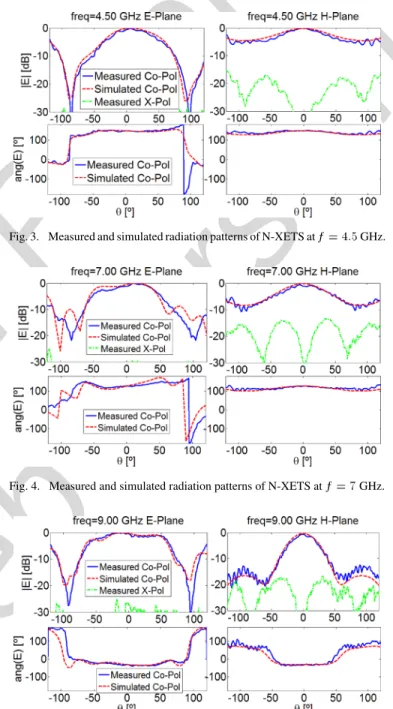
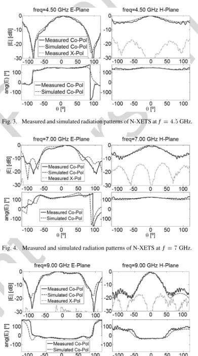
The measured and CST simulated input reflection coefficient for the N-XETS antenna are shown in Fig. 2, superimposed on measured curves from the reference antenna [4]. The mea-sured curve agrees well with simulations and demonstrates a good impedance match for both antennas over the full UWB from 3.1 to 10.6 GHz. For the N-XETS antenna (Fig. 1), the desired band rejection is centered at GHz and covers the desired 675-MHz bandwidth. Measured and simulated radi-ation patterns (amplitude and phase) for , 7, and 9 GHz are shown in Figs. 3–5. The unbalanced feeding originates a very slight lack of symmetry in the -plane radiation pattern and higher cross-polarization levels in the -plane due to stray common-mode currents. Nevertheless, cross-polarization level is quite low and stable across the frequency band. The phase characteristic is also quite constant in most of the solid angle for all frequencies, which translates into a well-defined phase center almost coincident with the antenna plane. The radiation pattern is bidirectional; however, the region is omitted be-cause it is blocked by the antenna supporting tower during mea-surements.
To evaluate the pulse-preserving performance of the N- XETS in a UWB link, two identical antennas where placed face-to-face separated by a distance of cm. Using a vector network analyzer (Agilent PNA E8361A) and after a full port calibration at the antenna terminals, measurements of were performed in an anechoic chamber between the input and output terminals of the transmitting and receiving antennas. The results in Fig. 6
Fig. 2. Reference and band-notched XETS antenna input reflection coefficient amplitude.
Fig. 3. Measured and simulated radiation patterns of N-XETS atf = 4:5 GHz.
Fig. 4. Measured and simulated radiation patterns of N-XETS atf = 7 GHz.
Fig. 5. Measured and simulated radiation patterns of N-XETS atf = 9 GHz.
show good agreement with simulated curves and demonstrate a very sharp decrease in magnitude at the desired band around
IEEE Proof
Web Version
Fig. 6. Link transfer function between two identical face-to-face band-notched XETS antennas separated byR = 25 cm: (a) amplitude; (b) phase.
Fig. 7. (a) Magnitude ofH , which is coincident with the antenna gain in dB. (b) Group delay of the N-XETS.
GHz. Outside the rejection band, the N-XETS perfor-mance is similar to the reference antenna [4]; see Fig. 6. For fre-quencies below the notch, the magnitude is reasonably con-stant and the unwrapped phase is almost linear. However, above the notch, the magnitude shows some perturbation although the phase is almost linear. The antenna transfer function , is obtained from the measured [8]. With appropriate normal-ization [8], the amplitude of the transfer function in decibels is identical to the antenna gain. Results shown in Fig. 7(a) demon-strate reasonable constant gain in the lower band and about 2 dB gain variation in the upper band. This is mainly due to the nar-rowing of the radiation pattern in the -plane, Fig. 5. The sharp gain decrease at the notch band is due to the intentional antenna input impedance mismatch seen in Fig. 2.
Fig. 7(b) shows the phase derivative of the transfer function, the group delay . It is nearly constant and close to zero with an expected oscillation in the notch band. This ensures that the phase center of the antenna is stable and very close to the an-tenna plane over the entire operating bandwidth.
IV. TIME-DOMAINPERFORMANCE
The degree of distortion that a link introduces in the trans-mission of a pulse depends not only upon the transfer function, but also on the input waveform and the associated spectrum. Two carrier-based Gaussian pulses [2] complying with FCC in-door spectrum mask (Fig. 8) are used separately for the UWB
Fig. 8. FCC indoor mask and complying spectrum of a test Gaussian pulse: (a) lower band; (b) upper band.
Fig. 9. Input and output pulse in time domain for a UWB link with two identical face-to-face band-notched XETS antennas: (a) lower band; (b) upper band.
lower band (3.1 to 5.15 GHz) and for the upper band ( 5.825 to 10.6 GHz) to evaluate the pulse-preserving performance of a link between two face-to-face identical N-XETS antennas. The central frequency of the lower band pulse is GHz with ns Gaussian width, while the upper band pulse has GHz and ns. The spectrum amplitudes of the input pulses and the transmitted pulses (EIRP at 1-MHz band-width of a single antenna at direction) are also presented in Fig. 8. The impulses fully comply with the FCC in-door spectrum mask, including a 10-dBm/MHz power decrease in the WLAN band. The received pulse can be calculated by multiplying the spectrum of the input pulse by the measured link transfer function and then applying an inverse Fourier trans-form. For better comparison, the output pulses shown in Fig. 9 are scaled in amplitude, divided by the maximum value of , and shifted in time to superimpose with the input pulses. The resulting normalized pulse amplitudes for the lower and upper bands are shown in Fig. 9. The output pulses preserve the gen-eral shape of the input pulses, with slight ringing in the output trailing edge.
To quantify the pulse distortion, two figures of merit are used: One is fidelity ( ) [9], the correlation coefficient between normalized input and output pulses. For ideal transmission without distortion, is 100%. The second figure of merit is the output-to-input ratio of the time window containing 90% of the pulse energy (RE90) [3]. For the measured output pulses in Fig. 9, we obtain , for the lower band, and , for the upper band.
IEEE Proof
Web Version
4 IEEE ANTENNAS AND WIRELESS PROPAGATION LETTERS, VOL. 8, 2009
Fig. 10. Fidelity of a single band-notched XETS antenna over the solid angle. The radial angle is theta, and the polar angle is phi: (a) lower band; (b) upper band.
Similar to previously presented results, again CST simula-tions show excellent agreement with measurements, which en-titles use of this simulator to estimate the fidelity of a single N-XETS antenna over the whole solid angle for the upper and lower bands; see Fig. 10. For the lower band of the N-XETS, fidelity values range from 90% to 95%. For the upper band, the fidelity values ranges from 80% in the - and -planes near to 95% in most of the front and back hemispheres. The slight lack of overall symmetry is due to the feeding coaxial cable. Identical results were observed for RE90 parameter.
As foreseen from the link transfer function in Fig. 6, the an-tenna pulse-preserving capability is better in the lower band. Nevertheless, full compliance with UWB requirements are ob-tained for both bands, compatible with hundreds of Mb/s bit rates.
V. CONCLUSION
The study confirms that the proposed 35-mm-diameter UWB antenna based on a balanced uniplanar crossed-slot configura-tion offers an excellent rejecconfigura-tion of the full 675-MHz WLAN band centered at 5.5 GHz while maintaining the best charac-teristics of the original XETS design. In fact, experimental and simulation results show that, outside the rejection band, radia-tion pattern and polarizaradia-tion are quite stable versus frequency, and pulse-preserving characteristics are maintained over most of the solid angle. The antenna remains compact and low-profile (35-mm diameter and 10-mil thickness) and still enables use of a differential UWB chip transceiver directly on the back petals of the antenna. The antenna uses new optimized slots at the back face of the substrate, compatible with the high symmetry of the XETS, to achieve the above goals
ACKNOWLEDGMENT
The authors acknowledge the collaboration from V. Fred and C. Brito for prototype construction and A. Almeida for proto-type measurements.
REFERENCES
[1] “First order and report: Revision of Part 15 of the commission’s rules regarding UWB transmission systems,” FCC, FCC 02-48, 2002. [2] T. Ma and S. Wu, “Ultrawideband band-notched folded strip
monopole antenna,” IEEE Trans. Antennas Propag., vol. 55, no. 11, pp. 2473–2479, Nov. 2007.
[3] M. Klemm and G. Tröster, “Characterization of small planar antennas for UWB mobile terminals,” Wireless Commun. Mobile Comput., vol. 5, pp. 525–536, Aug. 2005.
[4] J. Costa, C. Medeiros, and C. Fernandes, “Performance of a crossed ex-ponentially tapered slot antenna for UWB systems,” IEEE Trans.
An-tennas Propag., vol. 57, no. 5, pp. 1345–1352, May 2009.
[5] Y. Cho, K. Kim, D. Choi, S. Lee, and S. Park, “Miniature UWB planar monopole antenna with 5-GHz band-rejection filter and the time-do-main characteristics,” IEEE Trans. Antennas Propag., vol. 54, no. 5, pp. 1453–1460, May 2006.
[6] CST- Computer Simulation Tech 2009 [Online]. Available: http://www.cst.com/
[7] A. Vorobyov et al., “Integration of a pulse generator on chip into a compact ultrawideband antenna,” IEEE Trans. Antennas Propag., vol. 56, no. 3, pp. 858–868, Mar. 2008.
[8] T. Ma and S. Jeng, “Planar miniature tapered-slot-fed annular slot an-tennas for ultrawide-band radios,” IEEE Trans. Anan-tennas Propag., vol. 53, no. 3, pp. 1194–1202, Mar. 2005.
[9] D. Lamensdorf and L. Susman, “Baseband-pulse-antenna techniques,”
IEEE Proof
Print Version
Compact Tapered Slot UWB Antenna
With WLAN Band Rejection
Carla R. Medeiros, Jorge R. Costa, Member, IEEE, and Carlos A. Fernandes, Senior Member, IEEE
Abstract—This letter extends the design of a previously
pro-posed uniplanar ultrawideband (UWB) antenna to include within its 3.1–10.6-GHz operation band a rejection of the wireless local area network (WLAN) band near 5.5 GHz. The antenna config-uration is based on a combination of two crossed exponentially tapered slots plus a star-shaped slot printed on both sides of a 10-mils dielectric substrate. The band rejection is obtained with the addition of extra slots at the antenna back-face metallization. The radiation pattern and polarization are very stable over the entire UWB. Link measurements between two identical antennas demonstrate low pulse distortion over almost all the solid angle.
Index Terms—Printed broadband antenna, tapered slot
an-tenna, ultrawideband (UWB) antennas, wireless local area network (WLAN) band rejection.
I. INTRODUCTION
U
LTRAWIDEBAND (UWB) radio is an emerging and promising technology for short-range applications en-abling extremely high data rate. This technology transmits very low-energy-level broadband pulses. In the U.S., the Federal Communications Commission (FCC) [1] authorized the unlicensed use of the 3.1–10.6-GHz spectrum for UWB applications with limited power spectral density emission to enable spectrum sharing with other established narrowband applications without mutual interference. UWB systems may, however, require the inclusion of band-rejection filters to avoid possible interference from existing wireless local area networks (WLANs), allocated from 5.15 to 5.825 GHz.Recently, the required WLAN band rejection is being incor-porated directly at the antenna [2] to avoid the addition of band-rejection filters in the UWB transceiver. This constitutes an ad-ditional challenge for UWB antenna design. Antennas are re-quired to be compact, low-profile, and low-cost while presenting good pulse-preserving performance. Also, impedance match, polarization, gain, and radiation pattern stability are critical over the entire UWB. For this purpose, planar printed technology is very attractive and has been widely used for full-band UWB
Manuscript received March 06, 2009. First published May 05, 2009; current version published nulldate.
C. R. Medeiros is with the Instituto de Telecomunicações, 1049-001 Lisboa, Portugal (e-mail: Carla.Medeiros@lx.it.pt).
J. R. Costa is with the Instituto de Telecomunicações, 1049-001 Lisboa, Por-tugal, and also with the Instituto Superior de Ciências do Trabalho e da Empresa, 1649-026 Lisboa, Portugal (e-mail: Jorge.Costa@lx.it.pt).
C. A. Fernandes is with the Instituto de Telecomunicações and the Instituto Superior Técnico, 1049-001 Lisboa, Portugal (e-mail: Carlos.Fernandes@lx.it. pt).
Color versions of one or more of the figures in this letter are available online at http://ieeexplore.ieee.org.
Digital Object Identifier 10.1109/LAWP.2009.2022063
antenna configurations. Most planar antenna configurations in the literature are based on dipole/monopole configurations [3] or on slot-based antennas [4]. The addition of the band-notch is mainly obtained through some modification of the full-band solution—for example, by adding slots [5] to the antenna met-allization.
The authors recently proposed in [4] a very compact printed planar slot-based UWB antenna. It is a balanced configuration that exhibits excellent polarization and radiation pattern sta-bility over the full UWB while maintaining low pulse distortion over a very broad solid angle. It was referenced as the crossed exponentially tapered slot antenna (XETS). The present letter extends the previous antenna solution by adding the WLAN band-rejection characteristic with the inclusion of additional op-timized slots. A complete evaluation of the new antenna perfor-mance both in frequency and time domains shows that the pre-vious excellent characteristics in terms of radiation pattern sta-bility and pulse distortion are maintained in the lower and upper subbands, remaining complaint with all FCC requirements and corroborating the potential of the proposed antenna for UWB applications. The band-notched version of the antenna is re-ferred as N-XETS for brevity.
II. ANTENNADESCRIPTION
The original antenna presented in [4] is used as reference for comparison purposes. The front face of the antenna consists of a circular metal layer with two crossed exponentially tapered slots, intersected by a star-like slot, as inFig. 1(a). On the back-side of the substrate, chopped replicas of two front-face “petals” are duplicated, shown in Fig. 1. The two backside petals are di-rectly fed by a microcoaxial cable and couple capacitively at RF with the parallel front petals of the antenna. The antenna’s perfect symmetry with respect to feed point ensures intrinsic pure linear polarization versus frequency, defining the -plane ( ), while the absence of a ground plane allows a bidirec-tional radiation pattern.
The modifications on the reference antenna needed to produce the band-notched characteristics without impairing the antenna UWB performance were applied to its back-face metallization. Appropriate symmetric slots were added to the “back petals” to force there a frequency-dependent be-havior of the current distribution. The slots’ width, length, and V-angle [Fig. 1(a)-(b)] were optimized to obtain the desired input impedance mismatch from 5.15 to 5.825 GHz, with minimum influence on the remaining band. CST Microwave Studio transient solver [6] was used for the antenna design and optimization.
IEEE Proof
Print Version
2 IEEE ANTENNAS AND WIRELESS PROPAGATION LETTERS, VOL. 8, 2009
Fig. 1. (a) Photograph of fabricated N-XETS antenna in front of a mirror to show front face and back face; (b) back face of the N-XETS (zoomed).
Both faces of the antenna prototype are shown in Fig. 1. The substrate is 10-mil-thick DUROID 5880 with permittivity
. The front-face slot dimensions are identical to the antenna in [4]. The new slots seen in Fig. 1(b), responsible for the band-notch, have the following dimensions: mm,
mm, mm, mm, mm, and . The antenna’s overall diameter is mm. Although a balanced antenna configuration is adopted here having in mind direct integration of differential RFICs at its back without RF cables or additional balun [7], the prototype is fed directly by a 50- semirigid microcoaxial cable with 0.047-in diameter [Fig. 1(a)] to make broadband measurements simpler. The thin cable produces low common-mode current with only marginal influence on the antenna performance [4].
III. FREQUENCYDOMAINPERFORMANCE
The measured and CST simulated input reflection coefficient for the N-XETS antenna are shown in Fig. 2, superimposed on measured curves from the reference antenna [4]. The mea-sured curve agrees well with simulations and demonstrates a good impedance match for both antennas over the full UWB from 3.1 to 10.6 GHz. For the N-XETS antenna (Fig. 1), the desired band rejection is centered at GHz and covers the desired 675-MHz bandwidth. Measured and simulated radi-ation patterns (amplitude and phase) for , 7, and 9 GHz are shown in Figs. 3–5. The unbalanced feeding originates a very slight lack of symmetry in the -plane radiation pattern and higher cross-polarization levels in the -plane due to stray common-mode currents. Nevertheless, cross-polarization level is quite low and stable across the frequency band. The phase characteristic is also quite constant in most of the solid angle for all frequencies, which translates into a well-defined phase center almost coincident with the antenna plane. The radiation pattern is bidirectional; however, the region is omitted be-cause it is blocked by the antenna supporting tower during mea-surements.
To evaluate the pulse-preserving performance of the N- XETS in a UWB link, two identical antennas where placed face-to-face separated by a distance of cm. Using a vector network analyzer (Agilent PNA E8361A) and after a full port calibration at the antenna terminals, measurements of were performed in an anechoic chamber between the input and output terminals of the transmitting and receiving antennas. The results in Fig. 6
Fig. 2. Reference and band-notched XETS antenna input reflection coefficient amplitude.
Fig. 3. Measured and simulated radiation patterns of N-XETS atf = 4:5 GHz.
Fig. 4. Measured and simulated radiation patterns of N-XETS atf = 7 GHz.
Fig. 5. Measured and simulated radiation patterns of N-XETS atf = 9 GHz.
show good agreement with simulated curves and demonstrate a very sharp decrease in magnitude at the desired band around
IEEE Proof
Print Version
Fig. 6. Link transfer function between two identical face-to-face band-notched XETS antennas separated byR = 25 cm: (a) amplitude; (b) phase.
Fig. 7. (a) Magnitude ofH , which is coincident with the antenna gain in dB. (b) Group delay of the N-XETS.
GHz. Outside the rejection band, the N-XETS perfor-mance is similar to the reference antenna [4]; see Fig. 6. For fre-quencies below the notch, the magnitude is reasonably con-stant and the unwrapped phase is almost linear. However, above the notch, the magnitude shows some perturbation although the phase is almost linear. The antenna transfer function , is obtained from the measured [8]. With appropriate normal-ization [8], the amplitude of the transfer function in decibels is identical to the antenna gain. Results shown in Fig. 7(a) demon-strate reasonable constant gain in the lower band and about 2 dB gain variation in the upper band. This is mainly due to the nar-rowing of the radiation pattern in the -plane, Fig. 5. The sharp gain decrease at the notch band is due to the intentional antenna input impedance mismatch seen in Fig. 2.
Fig. 7(b) shows the phase derivative of the transfer function, the group delay . It is nearly constant and close to zero with an expected oscillation in the notch band. This ensures that the phase center of the antenna is stable and very close to the an-tenna plane over the entire operating bandwidth.
IV. TIME-DOMAINPERFORMANCE
The degree of distortion that a link introduces in the trans-mission of a pulse depends not only upon the transfer function, but also on the input waveform and the associated spectrum. Two carrier-based Gaussian pulses [2] complying with FCC in-door spectrum mask (Fig. 8) are used separately for the UWB
Fig. 8. FCC indoor mask and complying spectrum of a test Gaussian pulse: (a) lower band; (b) upper band.
Fig. 9. Input and output pulse in time domain for a UWB link with two identical face-to-face band-notched XETS antennas: (a) lower band; (b) upper band.
lower band (3.1 to 5.15 GHz) and for the upper band ( 5.825 to 10.6 GHz) to evaluate the pulse-preserving performance of a link between two face-to-face identical N-XETS antennas. The central frequency of the lower band pulse is GHz with ns Gaussian width, while the upper band pulse has GHz and ns. The spectrum amplitudes of the input pulses and the transmitted pulses (EIRP at 1-MHz band-width of a single antenna at direction) are also presented in Fig. 8. The impulses fully comply with the FCC in-door spectrum mask, including a 10-dBm/MHz power decrease in the WLAN band. The received pulse can be calculated by multiplying the spectrum of the input pulse by the measured link transfer function and then applying an inverse Fourier trans-form. For better comparison, the output pulses shown in Fig. 9 are scaled in amplitude, divided by the maximum value of , and shifted in time to superimpose with the input pulses. The resulting normalized pulse amplitudes for the lower and upper bands are shown in Fig. 9. The output pulses preserve the gen-eral shape of the input pulses, with slight ringing in the output trailing edge.
To quantify the pulse distortion, two figures of merit are used: One is fidelity ( ) [9], the correlation coefficient between normalized input and output pulses. For ideal transmission without distortion, is 100%. The second figure of merit is the output-to-input ratio of the time window containing 90% of the pulse energy (RE90) [3]. For the measured output pulses in Fig. 9, we obtain , for the lower band, and , for the upper band.
IEEE Proof
Print Version
4 IEEE ANTENNAS AND WIRELESS PROPAGATION LETTERS, VOL. 8, 2009
Fig. 10. Fidelity of a single band-notched XETS antenna over the solid angle. The radial angle is theta, and the polar angle is phi: (a) lower band; (b) upper band.
Similar to previously presented results, again CST simula-tions show excellent agreement with measurements, which en-titles use of this simulator to estimate the fidelity of a single N-XETS antenna over the whole solid angle for the upper and lower bands; see Fig. 10. For the lower band of the N-XETS, fidelity values range from 90% to 95%. For the upper band, the fidelity values ranges from 80% in the - and -planes near to 95% in most of the front and back hemispheres. The slight lack of overall symmetry is due to the feeding coaxial cable. Identical results were observed for RE90 parameter.
As foreseen from the link transfer function in Fig. 6, the an-tenna pulse-preserving capability is better in the lower band. Nevertheless, full compliance with UWB requirements are ob-tained for both bands, compatible with hundreds of Mb/s bit rates.
V. CONCLUSION
The study confirms that the proposed 35-mm-diameter UWB antenna based on a balanced uniplanar crossed-slot configura-tion offers an excellent rejecconfigura-tion of the full 675-MHz WLAN band centered at 5.5 GHz while maintaining the best charac-teristics of the original XETS design. In fact, experimental and simulation results show that, outside the rejection band, radia-tion pattern and polarizaradia-tion are quite stable versus frequency, and pulse-preserving characteristics are maintained over most of the solid angle. The antenna remains compact and low-profile (35-mm diameter and 10-mil thickness) and still enables use of a differential UWB chip transceiver directly on the back petals of the antenna. The antenna uses new optimized slots at the back face of the substrate, compatible with the high symmetry of the XETS, to achieve the above goals
ACKNOWLEDGMENT
The authors acknowledge the collaboration from V. Fred and C. Brito for prototype construction and A. Almeida for proto-type measurements.
REFERENCES
[1] “First order and report: Revision of Part 15 of the commission’s rules regarding UWB transmission systems,” FCC, FCC 02-48, 2002. [2] T. Ma and S. Wu, “Ultrawideband band-notched folded strip
monopole antenna,” IEEE Trans. Antennas Propag., vol. 55, no. 11, pp. 2473–2479, Nov. 2007.
[3] M. Klemm and G. Tröster, “Characterization of small planar antennas for UWB mobile terminals,” Wireless Commun. Mobile Comput., vol. 5, pp. 525–536, Aug. 2005.
[4] J. Costa, C. Medeiros, and C. Fernandes, “Performance of a crossed ex-ponentially tapered slot antenna for UWB systems,” IEEE Trans.
An-tennas Propag., vol. 57, no. 5, pp. 1345–1352, May 2009.
[5] Y. Cho, K. Kim, D. Choi, S. Lee, and S. Park, “Miniature UWB planar monopole antenna with 5-GHz band-rejection filter and the time-do-main characteristics,” IEEE Trans. Antennas Propag., vol. 54, no. 5, pp. 1453–1460, May 2006.
[6] CST- Computer Simulation Tech 2009 [Online]. Available: http://www.cst.com/
[7] A. Vorobyov et al., “Integration of a pulse generator on chip into a compact ultrawideband antenna,” IEEE Trans. Antennas Propag., vol. 56, no. 3, pp. 858–868, Mar. 2008.
[8] T. Ma and S. Jeng, “Planar miniature tapered-slot-fed annular slot an-tennas for ultrawide-band radios,” IEEE Trans. Anan-tennas Propag., vol. 53, no. 3, pp. 1194–1202, Mar. 2005.
[9] D. Lamensdorf and L. Susman, “Baseband-pulse-antenna techniques,”