José Alexandre Pires Ferreira
Licenciado em Ciências de Engenharia
Monitoring morphisms to support
sustainable interoperability of enterprise
systems
Dissertation to obtain the Master degree in Electrical Engineering
and Computer Science
Orientador: Ricardo Luís Rosa Jardim Gonçalves
Professor Auxiliar, Departamento de Engenharia Electrotécnica
Faculdade de Ciências e Tecnologia da Universidade Nova de Lisboa
Orientador: Carlos Manuel Melo Agostinho, Investigador, UNINOVA
Júri:
Presidente: Doutor José António Barada de Oliveira
Arguente: Doutor João Pedro Mendonça de Assunção da Silva Vogais: Doutor Ricardo Luís Rosa Jardim Gonçalves
Mestre Carlos Manuel de Melo Agostinho
s
Copyright
Monitoring morphisms to support sustainable interoperability of enterprise systems© José
Alexandre Pires Ferreira
A
CKNOWLEDGEMENTS
I would like to thank all the people who, in some way, supported me during the realisation of my course and this dissertation.
First my family, that never gave up on me during the end of this phase of my life, which supported me all these years. To my brother that helped me during the time I was writing this dissertation.
To Sónia that was my last motivation and help to finally finish the course and this dissertation, that gave me hope and believed in me, thus made me believe in myself. And kept me motivated and pushed me all the time in order to finish the dissertation.
To all my colleagues at GRIS, especially to Carlos Agostinho that helped and believed in me all this time, pushing me to do a better work and to successfully complete this dissertation. João Sarraipa to the help he gave me during the dissertation.
To my advisor Dr. Ricardo Gonçalves for believing in my capabilities and giving me his advice towards the successful completion of this work, and the great opportunity to work in his group.
Finally, to my special friends, who shared all the hard work during the course, that took too many years, but finally is over. Thank you Paulo Polaina, Francisco Cavaco and António Paulo, for all these years together and the great nights we passed together.
A
BSTRACT
Nowadays, organizations are required to be part of a global collaborative world. Sometimes this is the only way they can access new and wider markets, reaching new opportunities, skills and sharing assets, e.g. tools, lessons learnt. However, due to the different sources of enterprise models and semantics, organizations are experiencing difficulties in exchanging vital information via electronic and in a seamlessly way. To solve this issue, most of them try to attain interoperability by establishing peer-to-peer mappings with different business partners, or in optimized networks using neutral data standards to regulate communications. Moreover, the systems are more and more dynamic, changing frequently to answer new customer’s requirements, causing new interoperability problems and a reduction of efficiency. This dissertation proposes a multi-agent system to monitor existing enterprise systems, by being capable of detecting morphism changes. With this, network harmonization breakings are timely detected, and possible solutions are suggested to regain the interoperable status, thus enhancing robustness for reaching sustainability of business networks.
K
EYWORDS
R
ESUMO
Hoje em dia, as organizações têm a necessidade de se integrarem no mundo global e colaborativo. Por vezes esta é a única forma que estas têm para alcançar novos e maiores mercados, competências e partilha de recursos. No entanto, devido às diversas fontes de modelos empresariais e semântica, as organizações estão a enfrentar dificuldades na troca de informações em formato electrónico. Para resolver este problema, é prática tentar alcançar-se a interoperabilidade através mapeamentos ponto a ponto com os diversos parceiros de negócios, ou através de redes optimizadas, que usam normas de modelos de dados para regular as comunicações dentro da rede colaborativa. Além disso, os sistemas são cada vez mais dinâmicos, sofrendo assim, frequentes alterações como resposta à exigência apresentada por novos clientes, causando problemas de interoperabilidade e uma redução de eficiência. Este trabalho, propõe um sistema de motivação baseada em multi-agentes, capaz de detectar alterações nos morfismos do “Communicator Mediator”. Assim, as quebras de harmonização numa rede colaborativa são detectadas a tempo, e o sistema é capaz de sugerir possíveis soluções para recuperar o estado interoperável, aumentando assim a robustez e por consequência alcançar a sustentabilidade das redes de negócios.
P
ALAVRAS
-C
HAVE
T
ABLE OF
A
CRONYMS
ACC Agent Communication Channel ACL Agent Communication Language AMS Agent Management System AP Application Protocol
ATHENA Advanced Technologies for interoperability of Heterogeneous Enterprise Networks
ATL ATLAS Transformation Language BDA Behavioural Digital Aircraft
C4IF Connection, Communication, Consolidation, Collaboration Interoperability Framework
CAD Computer-Aided Design CAE Computer-Aided Engineering CAS Complex Adaptive Systems
CAS-SIF CAS to support Sustainable Interoperability Framework CIM Computer Independent Model
CM Communicator Mediator CN Collaboration Network
CRESCENDO Collaborative and Robust Engineering using Simulation Capability Enabling Next Design Optimisation
CWM Common Warehouse Metal Model DF Director Facilitator
EI Enterprise Interoperability
EIF European Interoperability Framework ENS Event Notification Service
ERP Enterprise Resource Planning ES Enterprise Systems
EPS European Public Services
EU Europe Union
FIPA Foundation for Intelligent Physical Agents
ICT Information and Communication Technology IEC International Electrotechnical Commission IEEE Institute of Electrical and Electronics Engineers IL & ML Interoperability Layers and Maturity Levels IM Information Model
INTEROP Interoperability Research for Networked Enterprises Applications and Software IS Information Systems
ISA Industry Standard Architecture
ISO International Organisation for Standardization (http://www.iso.org)
iSURF An Interoperability Service Utility for Collaborative Supply Chain Planning across Multiple Domains Supported by RFID Devices
IT Information Technology
JADE Java Agent DEvelopment framework
KB Knowledge Base
LC Life Cycle
LISI Levels of Information System Interoperability MAS Multi-Agent System
MBSE Model Driven-Based Engineering MDA Model Driven Architecture MDD Model Driven Development MDE Model Driven Engineering MDI Model Driven Interoperability
MIRAI Monitoring morphIsms to suppoRt sustAinable Interoperability of enterprise systems
MOF Meta Object Facility MoMo Model Morphism
MSI Modelling and Simulation Interoperability
OMG Object Management Group (http://www.omg.org) OWL Web Ontology Language
P2P Peer to Peer
PIM Platform Independent Model PLC Product Life Cycle
SE Systems Engineering
STEP Standard for the Exchange of Product Data SysML System Modelling Language
TTCN Tree and Tabular Combined Notation
UDDI Universal Description, Discovery and Integration UML Unified Modelling Language
UNINOVA Institute for the Development of New Technology VHDL VHSIC Hardware Description Language
WAN Wide Area Networks
T
ABLE OF
C
ONTENTS
Acknowledgements ... vi
Abstract ... viii
Resumo ... x
Table of Acronyms ... xii
Table of Contents ... xvi
Table of Figures ... xviii
List of Tables ... xx
1. Introduction ... 1
1.1.
Research Framework and Motivation ... 2
1.2.
Research Method ... 3
1.3.
Research Problem and Questions ... 4
1.4.
Hypothesis ... 4
1.5.
Dissertation Outline ... 4
2. Model-Based Systems Engineering ... 7
2.1.
Requirements and Benefits of Modelling... 8
2.2.
Product Life Cycle ... 9
2.3.
MBSE Information Models and Data Standards for Interoperability ...12
2.4.
Systems Engineering Ontology ...16
2.5.
Open Research Issues ...16
3. Enterprise Systems Interoperability ...19
3.1.
Interoperability Layers and Maturity Levels (IL & ML) ...19
3.2.
Model-Driven Interoperability ...26
3.3.
Semantic Interoperability ...29
3.4.
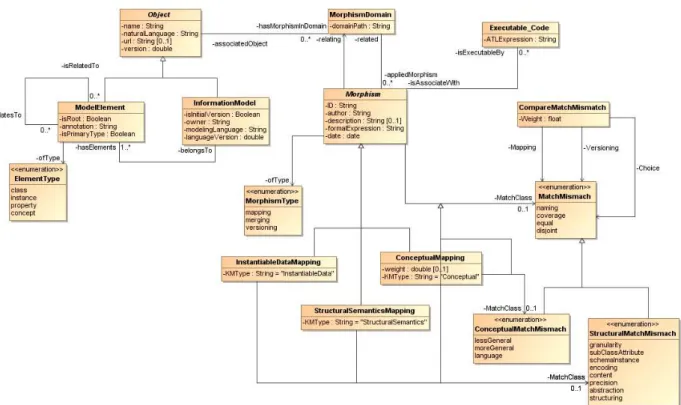
Model Morphisms ...29
3.5.
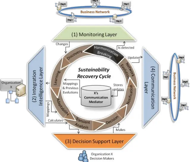
CAS-Based Framework to Support Sustainable Interoperability (CAS-SIF) ...34
3.6.
Open Research Issues ...35
4. Multi-Agent Systems (MAS) to support sustainable interoperability ...37
4.1.
MAS Overview ...38
4.2.
MIRAI Framework and Architecture...39
4.3.
Communication Mediator (CM) ...41
4.4.
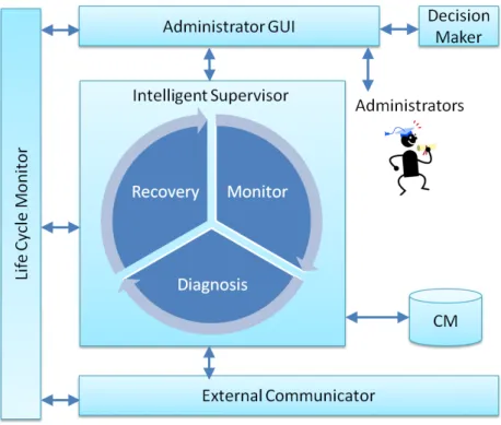
MIRAI Intelligent Supervisor Block ...42
4.5.
MIRAI External Communicator Block ...49
4.6.
MIRAI Administration Block ...51
4.7.
MIRAI Life Cycle Monitor Block ...52
4.8.
MIRAI Usability Cases ...54
5. Proof-of-concept Implementation ...57
5.2.
Implementation Steps ...64
5.3.
Implementation Overview and Technology Used ...68
6. Testing and Hypothesis Validation ...73
6.1.
Testing Methodologies ...73
6.2.
Requirements and Functionalities...77
6.3.
Testing ...79
6.4.
Hypothesis Validation ...86
6.5.
Scientific Validation ...86
6.6.
Industrial Validation ...87
7. Final Considerations and Future Work ...89
7.1.
Future Work ...90
8. References ...93
9. Annex ...97
T
ABLE OF
F
IGURES
Figure 1-1 - Phases of the Classical Research Method (based on (Camarinha-Matos 2010)) ... 3
Figure 2-1 - MBSE scope (adapted from (Nallon 2003), (Friedenthal et al. 2008)) ... 7
Figure 2-2 - Life Cycle based on ISO/IEC 15288 (Nallon 2003) ... 10
Figure 2-3
–
Life Cycle development model
s
: (a) Waterfall, (b) Spiral, (c) "Vee" (Estefan 2007) ... 12
Figure 2-4 - SysML diagram types (OMG 2011a) ... 13
Figure 3-1 - C
4IF Framework (Peristeras & Tarabanis 2006) ... 20
Figure 3-2 - LISI interoperability maturity model (C4ISR 1998) ... 21
Figure 3-3 - ATHENA MDI Framework (ATHENA 2010) ... 22
Figure 3-4 - EIF Framework (ISA 2010) ... 23
Figure 3-5 - Interoperability Classification Framework (H. Panetto 2007) ... 24
Figure 3-6 - Interoperability Practices Layers (Carlos Agostinho & Ricardo Jardim-Goncalves 2009) .. 25
Figure 3-7 - The levels of MDA approach (Petzmann et al. 2007) ... 28
Figure 3-8 - The relationship between model and meta-model (B Selic 2003) ... 30
Figure 3-9 - Example of mappings between two ontologies ... 31
Figure 3-10 - CAS-SIF Framework (Carlos Agostinho & Ricardo Jardim-Goncalves 2009) ... 34
Figure 4-1 - MIRAI Network ... 39
Figure 4-2 - MIRAI Architecture ... 40
Figure 4-3
–
Structure of Communication Mediator (J. Sarraipa et al. 2010) ... 42
Figure 4-4 - System to re-adapt the mappings ... 42
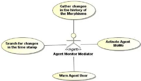
Figure 4-5 - Use Case of Agent Monitor Mediator ... 43
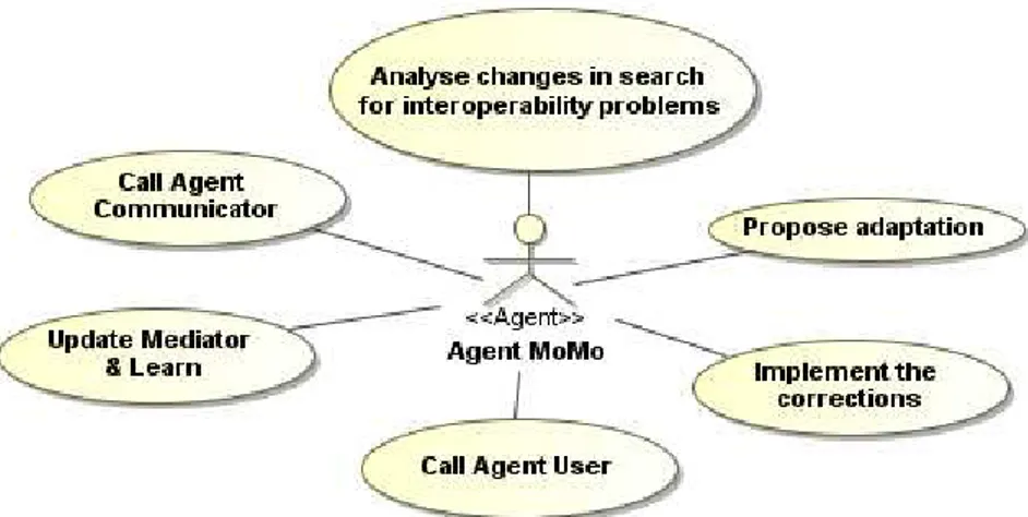
Figure 4-6 - Use Case of Agent MoMo ... 44
Figure 4-7 - MIRAI High Level Interaction ... 44
Figure 4-8 - State Machine of Intelligent Supervisor... 45
Figure 4-9 - Diagram sequence of Intelligent Supervisor and External Communicator with internal
problem ... 46
Figure 4-10 - Diagram sequence of Intelligent Supervisor and External Communicator with external
problem ... 47
Figure 4-11 - Detection and propose of morphisms ... 48
Figure 4-12 - Mappings between the models ... 48
Figure 4-13 - Use Case of Agent Communicator ... 50
4-14 - Actions of the Agent Communicator ... 50
Figure 4-15 - Use Case of Agent User ... 51
4-16 - Interaction between the Agent User and the rest of the agents ... 52
Figure 4-17 - Use Case of Agent Persistor ... 52
Figure 4-18 - Use Case of Agent Persistor Police ... 53
Figure 4-19 - State Machine of Life Cycle Monitor ... 53
Figure 4-20 - Diagram Sequence of Life Cycle Monitor ... 54
Figure 4-21
–
Morphism Evolution Scenario ... 54
Figure 4-22
–
New Enterprise Scenario ... 55
Figure 4-23
–
New Connection Scenario ... 55
Figure 4-24
–
Removal of an Enterprise Scenario ... 56
Figure 5-2
–
Representation of the mappings between the models without the evolution in the
system ... 59
Figure 5-3 - Representation of the mappings between the models with the evolution in the system 60
Figure 5-4 - Mappings of the scenario... 61
Figure 5-5 - Reacting of the network caused by a change of software ... 62
Figure 5-6
–
Scenario of concepts mappings ... 63
Figure 5-7
–
Mappings of the concepts ... 63
Figure 5-8 - MIRAI Architecture ... 64
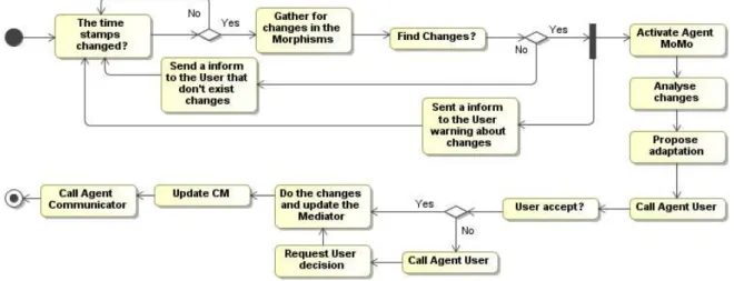
Figure 5-9 - Activity Diagram of Agent Monitor Mediator and Agent MoMo ... 65
Figure 5-10 - Example of new MatchClass creation ... 66
Figure 5-11 - Example of a mapping ... 67
Figure 5-12 - Web Service Scenario ... 68
Figure 6-1 - Family example ... 79
Figure 6-2 - Mapping relating Name in EXPRESS with Family Name in EXPRESS 2 ... 80
Figure 6-3 - MIRAI GUI and creating Agents... 80
Figure 6-4 - Agent Persistor resurrecting a Dead Agent... 81
Figure 6-5 - Agent Monitor Mediator working ... 83
Figure 6-6 - Agente MoMo proposing a possible solution ... 84
Figure 6-7 - Proposal of a new morphism ... 84
Figure 6-8 - Asking to the user to choose solution ... 85
L
IST OF
T
ABLES
Table 3-1 - Semantic Mismatches (based on (Carlos Agostinho et al. 2011)) ... 32
Table 5-1
–
Purpose of the used technology by the Proof-Of-Concept Implementation ... 69
Table 6-1 - Simplified example of a TTCN table test ... 77
Table 6-2 - Agent Persistor functional test ... 81
Table 6-3 - Agent Persistor Police functional tests... 82
Table 6-4 - Agents Persistor's non-functional tests ... 82
Table 6-5 - Agent Monitor Mediator functional test... 83
Table 6-6 - Agent Monitor Mediator non-functional test ... 84
Table 6-7 - Agent MoMo functional test ... 85
1. I
NTRODUCTION
In the last few years, collaboration between different enterprises have increased significantly with the possibility of combining resources towards achieving a common goal, as well as having to boost productivity and reduce expenses. Thus the chances of survival of smaller enterprises in the current turbulent market are increasing (Hassell et al. 2006). The enterprises are then forced to be adaptable with other enterprises network environments in order to have a collaborative business, while following all the Product Life Cycle (PLC) phases (C. Agostinho, Malo, et al. 2007).
Schrage (Schrage 1990), emphasizes that the issue in collaboration “is the creation of value”. In this context, not only data exchange in industrial process (e.g. supply chain, e-procurement, etc), but also in Systems Engineering (SE) has been the target of multiple collaborative networks. It demands the combination of multiple complex processes, such as requirements elicitation, product design and development, teams’ management, logistics, etc, that normally are performed in conjunction by different enterprises. The systems engineering method recognizes each system as an integrated whole though composed of diverse, specialized structures and sub-functions that aid in the development and Life Cycle (LC) of a product, using information and product models to describe and integrate the whole process (Chestnut 1965).
In this sense, being defined as the ability that two or more systems have to exchange information and use it accurately (Geraci et al. 1991), interoperability, namely the lack of it, could disturb the functionalities of the enterprise systems networks and decrease their competitiveness and innovation. Thus, it is important to maintain the interoperability, since it is a key concern for network enabled complex systems, which in turn have eased the collaborative enterprise and implicitly globalisation (Kotze & Neaga 2010).
However, in our days, when achieved, this stability is hard to maintain since due to market requirements and the increasingly dynamicity of customer needs, business requirements are constantly being adapted, causing systems, models and semantics to change, thus leading to harmonization breaking and disruption of the interoperability in the enterprise systems networks (Carlos Agostinho & Ricardo Jardim-Goncalves 2009).
These problems are the cause of the breaking of the harmonization in the interoperability. These occur because of different issues, and are described by Kotzé and Neaga in (Kotze & Neaga 2010):
Using standards do not always guarantee achieving interoperability;
There is a need for analysis and evaluation of interoperability itself;
Improvements of existing system interoperability should be beneficial;
Rapid development of technology may decrease the degree of systems interoperability if the interoperability requirements are not considered at design level.
There are several approaches, from different perspectives, to achieving interoperability (Kotze & Neaga 2010). Since, almost all the solutions try to solve the problems of interoperability, and that is part of the possible solution. Because, as already mentioned, for different reasons, sometimes it is not possible to maintain that, it is also needed to monitor and support the system, and this is another part of the problem, maintain the interoperability status.
This is the motivation behind of this thesis, to advance the research on organizations interoperability using a multi-agents framework to monitor the mappings between the different organizations and maintain the interoperability state. Using tuples suggested by Agostinho et al. (Carlos Agostinho et al. 2011), as a possible solution to the problem on the modelling of data, semantic and structural mappings as traceable tuples that when integrated in knowledge bases that are dedicated to managing mismatches during communications, so that network evolutions can be closely monitored and reactions can be triggered automatically.
1.1. Research Framework and Motivation
With each passing day the need to share information is becoming more and more important for the organisations, even more important is that failures never occur in that information. It is important to help the integration of the PLC phases, since manufacturers, distributors, designers, retailers, warehouses, all have their proprietary solutions, so maintaining interoperability between them is crucial (Ricardo Jardim-Goncalves, Carlos Agostinho, et al. 2011).
Carlos Agostinho, et al. 2011), thus using the MBSE paradigm to describe the PLC.
So, this dissertation aims to contribute to maintain the interoperability status of a collaborative network, by doing an inspection in the information and warning whenever there is a lack of interoperability. By doing this, there will be less waste of time, either at production line or by searching for a possible solution.
1.2. Research Method
The research method used in this dissertation is based on the classical research method (Camarinha-Matos 2010) and consists on seven steps. This method begins with the search of the problem, and ends with the interpretation of the results. If for some reason the results are unsatisfactory this method allows to return to the first step and experiment a new approach. This method is represented in Figure 1-1.
Figure 1-1 - Phases of the Classical Research Method (based on (Camarinha-Matos 2010))
Each step of this method is described below:
1. Research Question / Problem: It is the most important step in a research, because it is here that the area of interest is defined. It is possible that several secondary questions appear in order to help define the main idea. These questions are located in the section 1.3.
2. Background / Observation: Here is the section to do the research for the state of the art, by studying previously similar works, presenting literature review and previously projects with the objective to help start the dissertation. This is important because previous works will have an impact on the new one, and help in a new approach. So, showing existing ideas of other authors will create and open new solutions, to be used in the development for this dissertation. This background is located in the section 2 and 3.
4. Design Experiment: In this step the detailed plan of the experimental phase steps that is often compost by the design of a prototype or even system architecture is presented. The section 4 and 5 are the design of a prototype and the proof-of-concept, respectively.
5. Test Hypothesis / Collect Data: In this phase the evaluation of the system architecture is made. This is made by testing and simulating different scenarios. In each test data for further analysis and hypothesis validation is collected. These tests are done in section 6.2. 6. Interpret / Analyze Results: Here is where the results are analysed and the veracity of the hypothesis is found out. If for some reason the results are not satisfactory, it is possible to try a different approach, and return to step 1. Moreover, when positive results are achieved, it is possible to look to next steps giving some ideas for further research. This is made in the sections 6.2 and 6.3.
7. Publish Findings & Transfer to Industry: When good results are achieved and a good contribution to the scientific community is made, it is important to share these results with the community and in some cases transfer the technology to industry. To present the results to the scientific community is made using different means, like scientific paper, in conferences, Journals, and so on. In the case of the industry it is very important to accept the results, so it can be used. The scientific validation is presented in section 6.5 and the industrial validation is presented in section 6.6.
1.3. Research Problem and Questions
Is it possible to maintain the interoperability status in a collaborative network, responding to system’s changes and models evolution?
o In a network of enterprises, how is it possible to detect information model changes and system's evolutions?
o Can Multi-Agent Systems (MAS) propose possible mapping morphisms readjustments to system administrators?
o How will the Network receive the knowledge about the changes at the enterprise level?
1.4. Hypothesis
If the MIRAI framework is able to monitor the system and detect evolutions in the model morphisms at the enterprise level, then it is possible to detect changes in the systems information models, and create new mappings, thus re-enabling network interoperability.
1.5. Dissertation Outline
product, information models and MBSE ontology. Section 3 does a brief description of some approaches to classify the interoperability layers, and then covers the Model-Driven Interoperability (MDI) method for systems development and implementation, where a brief description of the Model-Driven Architecture (MDA) and Model-Model-Driven Engineering (MDE) is done. Later it will be described what semantic interoperability is and finally it will be introduced the model morphisms (MoMo).
Finally in section 4, a description about Multi-Agent Systems is done, and an explanation about the advantages of using MAS in the interoperability is presented. This section defines a framework based in MAS that has the objective of monitoring the existing mappings stored in each enterprise's Communicator Mediator (CM), with the aim to help the organisations to achieve the interoperability status. The proof-of-concept implementation steps are then presented in section 5, describing the architecture of the agents and how the monitor of the morphisms works. Section 6 is about the validation of the proof-of-concept implementation and the proposed framework, where the functional and non-functional tests of the framework are presented.
2. M
ODEL
-B
ASED
S
YSTEMS
E
NGINEERING
Usually in large projects the organizations employ a document-based systems engineering approach. This approach is characterized by the generation of textual specifications and design documents, in hard-copy or electronic file format, that are then exchanged between customers, users, developers, and testers. These documents and drawings represent the systems requirements and the design information, then the systems engineering are responsible on controlling the documentation and ensuring the documents and drawings are valid, complete, and consistent (Ogren 2000).
This method is rigorous but has some limitations, like the completeness, consistency, and relationships between requirements, design, engineering analysis, and test information. These are difficult to assess since the information is spread across several documents (Ogren 2000). Because of these limitations in SE and the need to improve the quality and to speed the access to information in 1993 the MBSE was introduced, with the intention to facilitate SE activities.
Figure 2-1 - MBSE scope (adapted from (Nallon 2003), (Friedenthal et al. 2008))
MBSE is the formalized application of modelling to support the systems engineering processes, namely requirements, design, analysis, verification and validation activities beginning at the conceptual design phase and continuing throughout development and later LC stages (Operations & Crisp II 2007), (INCOSE 2011).
the disposal of the product, then merged with the development process used in the MBSE, namely (Nallon 2003):
The requirements models that represent the relationships between user requirements and/or model objects. A primary benefit of modelling requirements is the opportunity this provides for analyzing them with techniques such as requirements animation, reasoning, etc (Nuseibeh & Easterbrook 2000), the examples of tools used to construct this models are the DOORS and ReqPro;
The behaviour models to represent the intended and unintended behaviours for a system of interest (e.g. a product), thus responding to functional requirements, the tools used to represent the behaviour models are the Use Case, Activity, Sequence and State Machine Diagram;
The parametric models to reply to the non-functional requirements representing the formal relationships and constraints of the system and its components. The tools used in the parametrics models are the Mathematic formulas and constraints;
And finally the structure models which describe the enterprise and system level contexts from both the logical and physical viewpoints. These are represented with External and Internal Block.
2.1. Requirements and Benefits of Modelling
Among the multiple ways to model a system or a product, there is no absolute recipe. However, modelling using MBSE need to have the requirements properly formalized so that the remaining models can be specified with a good level of detail and the final product can achieve the expected quality. Thus, Ogren (Ogren 2000) defines 5 key principles on modelling, namely:
Determinism with formality, so that everything expressed in the model has a single, defined
and obvious meaning;
Understandability, since systems engineering should be done in close cooperation with end
users,the models are only useful is they are readily understood, without extensive education or experience in software or mathematics;
Inclusion of system missions to be able to extract the systems missions out the models and
express how different parts of the system contribute together;
Modelling of structure and behaviour, to support splitting a system into subsystems, with
clarification of interfaces between these systems, and the modelling technique shall also allow a definition of behaviour within the subsystems defined;
Possibility of verification support, it should be possible to verify a completed model. This
These are the most important points to achieve an acceptable quality to modelling a complex system, with these requirements the use of the MBSE in the design of the PLC brings some benefits to the organizations,one of the most important benefits is to provide an opportunity to address many of the limitations of the document-based approach by providing a more rigorous means for capturing and integrating system requirements, design, analysis, and verification information, and facilitating the maintenance, assessment, and communication of this information across the system's life cycle. Other MBSE potential benefits are described on (Ogren 2000) and also described below:
Enhanced communications;
Shared understanding of the system across the development team and other stakeholders;
Ability to integrate views of the system from multiple perspectives; Reduced development risk
Ongoing requirements validation and design verification;
More accurate cost estimates to develop the system;
Improved quality
More complete, unambiguous, and verifiable requirements;
More rigorous traceability between requirements, design, analysis, and testing;
Enhanced design integrity; Increased productivity
Faster impact analysis of requirements and design changes;
Reuse of existing models to support design evolution;
Reduced errors and time during integration and testing;
Automated document generation; Enhanced knowledge transfer
Specification and design information captured in a standard format that can be accessed via query and retrieval.
Therefore, the MBSE framework can bring an added value to enterprise networks, maximizing the efficiency of collaborations and stimulating interoperability through the different models used along the system LC of the products.
2.2. Product Life Cycle
The purpose in defining life cycle of a system is to meet its required functionality throughout its life in an efficient manner. This is usually done by defining life cycle stages, and using decision gates to determine readiness to move from one stage to the next (Haskins 2006), (ISO 19760 2002).
2.2.1. Life Cycle Features
According to Haskins (Haskins 2006) the life cycle features are divided in two topics, the three aspects of the life cycle and the decision gates, the first describes that every system or product life cycle consists of three aspects, business aspect (business case), budget aspect (funding), and the technical aspect (product). It is important that these three aspects are in balance and given equal emphasis at all decision gate reviews.
The Decision gates ensure that new activities are not pursued until the previously scheduled activities (on which new ones depend) are satisfactorily completed and placed under configuration control (Haskins 2006).
The INCOSE in (Haskins 2006) proposed that the primary objectives of decision gates are to: Ensure that the elaboration of the business and technical baselines are acceptable and will
lead to satisfactory verification and validation;
Ensure that the risk of proceeding to the next step is acceptable;
Continue to foster buyer and seller teamwork.
In the beginning of each project at least two decision gates exist: authority to proceed and final acceptance of the project deliverable (Haskins 2006).
2.2.2. Life Cycle Stages
In the Figure 2-2 the six life cycle stages based on ISO/IEC 15288 (Nallon 2003) are represented, every stage has a purpose and a decision gate, the decision gate is equal for everyone, and can be one or more of the different gates that are represented here: Execute next stage; Continue this stage; Go to a preceding stage; Hold project activity and Terminate project. The purpose of each life cycle stage is described above and they are based on (Estefan 2007), (Faulconbridge & Ryan 2005):
Concept
The purpose of the Concept Stage is to assess new business opportunities and to develop preliminary system requirements and a feasible design solution.
In this stage, the studies to evaluate the concepts are done and a justification of the reason of the chosen concept is required. This evaluation differ from being hardware or software, in hardware mock-ups are made and in software created code, after that some engineering models and simulations are executed, since in some cases it is necessary to do more tests.
Some prototypes to help in the verification of the feasibility of the concepts and to explore risks and opportunities are then created. These studies are made to control the risk and opportunity evaluation to include affordability assessment, environmental impact, failure modes, and hazard analysis.
The objective of this study is to provide confidence that the business case is sound and the proposed solutions are achievable (Haskins 2006).
Development
The purpose of the Development Stage is to execute the development of the system-of-interest that meets acquirer requirements and can be produced, tested, evaluated, operated, supported, and retired.
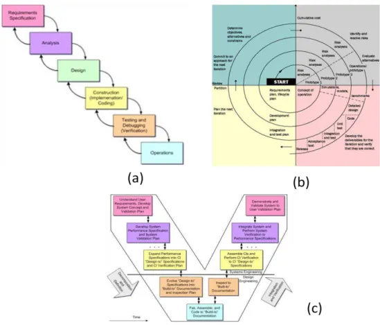
It is decided at this stage the baseline of the system components, where they are integrated and verified, it is here that the development of the individual subsystems and components in the system are then initiated. Some models that help in the evaluation of the system, within several existing models are used in the reinforcement of the subject. There are three models that are the most used (Figure 2-3): the Royce Waterfall Mode, Boehm's Spiral Model, and Forsberg and Moog's "Vee" Model. It is possible to pass to the next stage when the definition of the system is sufficiently detailed to commence the production.
Production
The purpose of the Production Stage is to produce or manufacture the product, to test the product, and to produce related supporting and enabling systems as needed.
The products will be produced following the design specifications defined in the concept stage. With the finished product in hand some tests are made and the product is evaluated to ensure that the final system configuration meets its intended purpose. This is needed because if for some reason the product has defects, thus detected in time, and causing the production to costs less. The production has to follow the documentation comprising the Product Baseline, so some auditions to control are made, if the auditions run successfully, the Product Baseline is approved.
Utilization
The purpose of Utilization Stage is to provide logistics, maintenance, and support services that enable continued system-of-interest operation and a sustainable service.
Figure 2-3 – Life Cycle development models: (a) Waterfall, (b) Spiral, (c) "Vee" (Estefan 2007)
Support
The purpose of the Support Stage is to provide logistics, maintenance, and support services that enable continued system-of-interest operation and a sustainable service.
In the LC of a product some supportability problems usually happens, so some modifications in the product to reduce operational costs or extend their life are proposed. These changes require systems engineering assessment to avoid loss of system capabilities while under operation.
Disposal
The Disposal Stage is to prepare the product for the removal of a system-of-interest and related operational and support services, and to operate and support the retirement system itself.
Since every product has one day to be retired from the market and with that it completes the entire life cycle of the product. At this point, the priority of the systems engineering is to ensure that the disposal requirements are satisfied. This phase was already planned for disposal as it is a part of the system definition during the concept stage.
2.3. MBSE Information Models and Data Standards for Interoperability
specify data semantics for a chosen domain of discourse (Lee 1999).
For example in the Figure 2-1 is a representation of the MBSE framework, and in the middle of the figure is an information model used to model the systems. When working with complex systems, becomes difficult to create this models, so to help in this, the MBSE suggest the use one of the two standard languages, i.e. SysML1 and AP2332, to help in the creation of system engineering models.
2.3.1. SysML
The System Modelling Language (SysML) is a graphical modelling language from the Object Management Group (OMG) that supports the analysis, specification, design, verification and validation of complex systems (Ogren 2000). The language was created to specify and architect systems and its components. With it, it is possible to integrate with UML for software design and VHDL3 for hardware design.
SysML was design to provide a simple but powerful construction for modelling a wide range of systems engineering problems. It is particularly effective in specifying requirements, structure, behaviour, allocations, and constraints on system properties to support engineering analysis. The language is intended to support multiple processes and methods such as structured, object-oriented, and others, but each methodology may impose additional constraints on how a construct or diagram kind may be used (OMG 2010).
Figure 2-4 - SysML diagram types (OMG 2011a)
The SysML includes nine diagrams as shown in the Figure 2-4. These diagrams are described above, along with its relationship to UML diagrams, and they are based on (Ogren 2000):
Requirement diagram represents text-based requirements and their relationship with other
1
Systems Modelling Language (SysML) - http://www.omgsysml.org/
2
STEP AP 233: Systems engineering data representation - http://www.ap233.org/
3
requirements, design elements, and test cases to support requirements traceability, they don't exist in UML;
Activity diagram represents behaviour in terms of the ordering of actions based on the
availability of inputs, outputs, and control, and how the actions transform the inputs to outputs, is a modification of UML activity diagram;
Sequence diagram represents behaviour in terms of a sequence of messages exchanged
between parts, is the same as UML sequence diagram;
State machine diagram represents behaviour of an entity in terms of its transitions between
states triggered by events, is the same as UML state machine diagram;
Use case diagram represents functionality in terms of how a system or other entity is used
by external entities (i.e., actors) to accomplish a set of goals, is the same as UML use case diagram;
Block definition diagram represents structural elements called blocks, and their composition
and classification, is a modification of UML class diagram;
Internal block diagram represents interconnection and interfaces between the parts of a
block, is a modification of UML composite structure diagram;
Parametric diagram represents constraints on property values, such as F=m*a, used to
support engineering analysis, not exist in UML;
Package diagram represents the organization of a model in terms of packages that contain
model elements, is the same as UML package diagram.
With these diagrams the SysML provides a means to capture the system modelling information as part of an MBSE approach without imposing a specific method on how this is performed (Ogren 2000).
2.3.2. AP233
The AP233 is a standard Application Protocol (AP) under STEP initiative (ISO/DIS 10303-233 2011), (ISO TC184/SC4 2004). ISO 10303 (STEP) is an international standard for the computer-interpretable representation of product information and for the exchange of product data. Its objective is to provide a means of describing product data throughout its LC, independent from any particular system (Frisch et al. 2007).
The product data are described using EXPRESS (OMG 2011b), the STEP modelling language, which combines methods from the entity-attribute-relationship languages with object modelling concepts. EXPRESS provides general and powerful mechanisms for representation of inheritance among the entities constituting the AP standard model, and it also encloses a full procedural programming language used to specify constraints on populations of instances.
are used to help in the MBSE LC of the product. Above are the different models based on (OSJTF 2006):
Behavioral Models is a data model that capture semantics associated with how a system acts or performs (responds to excitation); include functions, inputs, outputs and control operators which define the ordering of functions; includes both Function-based and State-based behaviors; enables generation of Functional Flow Block Diagrams, Finite State Machines, Causal Chain, Data Flows and Sequence Diagrams, etc;
Function-based Behavior Model is a data model that represents response to excitations based on the transformation of inputs into outputs by functions (activities) including the ordering and triggering of functions;
State-based Behavior Model is a data model that represents response to excitations in the digital approximation based on state of an object, transitions between states and actions or activities launched by the states or transitions;
Requirements is a data model that captures requirements as text strings with traceability, allocation, weighting and risk identified with each requirement [Text-based Requirements (TBR)] and that describes requirements as structured and quantified formalisms that may be decomposed from text-based requirements; can include tables, spreadsheets, graphs, charts, pictures and equations [Property-based Requirements (PBR)];
Allocation is a data model that captures allocation relationships between requirements and functions;
Structural Models is a data model that captures the organization of a system (e.g. how a system is built, static relationships between subsystems, components, or parts that constitute the system); describes what is designed, characterized built and maintained; Risk Analysis is a data model that identifies risk status, relationships, likelihood,
consequence, impact, approach strategy, and contingencies;
Rules are a data model that describes the information associated with constraints imposed on a product or process by system requirements, physical limitations and/or environmental restrictions. The model includes sufficient information to represent and/or support the constraint e.g. predicate calculus, the constraint life-cycle, constraint execution and associated meta-data, such as source, date and time, authorization, justification, description and notes;
Validation Modelis a data model that captures the information used to demonstrate that the emerging product is consistent with the stakeholder needs;
Verification Model is a data model that captures the information used to demonstrate that the emerging product is consistent with the system requirements;
models such as mechanical, electronic, structural analysis, thermal analysis, manufacturing, etc. e.g. the transform between engineering analysis (AP209, STEP-TAS, STEP-NRF, AP235, etc.) and any AP233 module set;
Data Presentation is a data model that provides a consistent set of presentation mechanisms and advanced schematics product model definitions that present the computer sensible model data (defined in representation model space) onto a human understandable schematic diagram (presentation space), conforming to conventional and/or future draughting standards;
Measurement is a data model that includes information associated with the product development process quantification and its control and optimization.
2.4. Systems Engineering Ontology
Collaboration and sharing of models requires the use of common terminology with well-defined meaning. For collaboration, the meaning of the models needs to be expressed without the models having to be accompanied by subject domain experts. Thus, for concepts like part of and product version, the informal meaning and even natural language definitions within standards are not sufficiently precise to rule out different interpretations for the same term (Beca et al. 2011).
Ontologies, which make these concepts precise, address this problem. Following very simple modelling principles, it uses classes, properties and relationships to describe and represent an area of knowledge defining the concepts and their relationships (Ehrig & Staab 2004). This way it is acceptable to conclude that it enables the creation of a kind of Lingua Franca for common understanding and exchanging (R. Jardim-Goncalves, C. Agostinho, et al. 2011).
Because of this matter, it was normal to implement ontologies in the system engineering with the intention to make implicit design artefacts explicit, such as ontologies representing process or service vocabularies relevant to some set of components (OMG 2009) and this will facilitate the ability to quickly develop models and to make their sharing easier.
The ontologies are used throughout the enterprise system development life cycle process to augment and enhance the target system as well as to support validation and maintenance. This is important because automated reasoning can mitigate engineering tasks that are currently manual, error prone, and time consuming.
2.5. Open Research Issues
looking for a solution to incorporate the diversity of models currently in use in SE (OMG 2011b). So far, the most common way to integrate models between different partners is to establish P2P mappings between the different models (Carlos Agostinho & Ricardo Jardim-Goncalves 2009).
3. E
NTERPRISE
S
YSTEMS
I
NTEROPERABILITY
Enterprise Systems (ES) are large-scale, integrated application-software packages that use the computational, data storage, and data transmission power of modern Information Technology (IT) to support processes, information flows, reporting, and data analytics within and between complex organizations. The integrated content may then be used to provide a configuration management solution throughout the life cycle in relation to the products, assets, processes and requirements of the entity (laboratory, facility, SDD, etc.) (US Departement of Energy 2011). An example of this integration is the MBSE that formalize applications to support the systems along the PCL.
Looking to this description, ES appear to be a dream come true, since commercial software packages promise the seamless integration of all the information flowing throughout the company. But if an organization has two systems and they cannot communicate with each other, then this will bring some problems in the manufacturing productivity and customer responsiveness suffers. This makes an organization's systems to become fragmented, meaning the business is also fragmented (Davenport 1998).
This is a problem for the organizations, a break in the systems that will difficult the efficiency and cooperation. Rather, the organizations need the ability for a system or a product to work with other systems or products without special effort on the part of the customer, this is what IEEE (Geraci et al. 1991) defines as interoperability. The IEEE also defines interoperability as the “ability of a system or a product that works with other systems or products without special effort on the part of the customer” (Geraci et al. 1991).
The lack of interoperability can be a great issue to the enterprises, so the modern enterprises have to be interoperable in terms of not only their IT systems, but also their business processes, their applications and even their human resources. Enterprises are concerned with interoperability between organisational units or business processes either within a large enterprise or within an enterprise network. The challenge lies in facilitating communication, cooperation, and coordination among these units and processes (Kotze & Neaga 2010), (Ray & Jones 2006). Because of these matters, this ability is gaining an important position in our days, since the organisations applications and software systems need to be interoperable in order to achieve seamless business across organisational boundaries.
In this section different maturity levels that categorize interoperability in different layers are presented, helping to distinguish the different problems and position the several interoperability frameworks available.
3.1. Interoperability Layers and Maturity Levels (IL & ML)
interoperability, all the previous levels have to be successfully addressed (Peristeras & Tarabanis 2006).
Maturity levels describe the stages through which they are defined, implemented, and improved. They have the objective of providing a guide to select improvement strategies by determining the current capabilities of specific processes and identifying the issues most critical to quality and process (C4ISR 1998).
A presentation of six well known interoperability typologies, are presented in the next sub-sections.
3.1.1. Connection, Communication, Consolidation, Collaboration Interoperability
Framework (C
4IF)
The C4IF was presented in (Peristeras & Tarabanis 2006) is a framework that use the basic linguistics concepts to the domain of Information System (IS) communication. With this concepts it was define four interoperability types in the framework, which are represented in the Figure 3-1 and described above:
Connection refers to the ability of information systems that exchange signals. To succeed in this, a physical contact/connection should be established between two (or more) systems; Communications refers to the ability to exchange data in IS's. To succeed in this, a
predefined data format and/or schema need to be accepted by the interlocutors;
In this type at least two levels of communication exist, the first level is the exchange based on a commonly accepted data format, the second level is more advanced, and the exchange includes data;
Consolidation refers to the ability of IS's to understand data. To succeed in this, a commonly
accepted meaning for the data needs to be established between the interlocutors;
Collaboration refers to the ability of systems to act together. Action results in changes in the
real world. To succeed in this, a commonly accepted understanding for performing functions / services / processes / actions needs to be established between the interlocutors or IS's. One of the greatest advantages is that the three areas are considered disjoint;
Another concept presented in this work, is the three demarcated areas where the four interoperability types are organized. The three areas are:
o Channel refers to the connection layer and the ability of IS's to exchange signals;
o Information refers to the communication and the consolidation layers, and the ability of IS's to exchange data and information;
o Process refers to the collaboration layer and the ability of IS's to act together.
3.1.2. Levels of Information System Interoperability (LISI)
An early classification was defined in the Levels of Information System Interoperability (LISI) (C4ISR 1998), which focuses on assessing systems against increasing levels of sophistications that focus in exchanging and sharing information and services through the system's life cycle. This occurs through five layer represented in Figure 3-2 and that are described below:
Level 0 - Isolated Interoperability in a Manual Environment. These systems cover the wide
range of isolated, or stand-alone, systems. Direct electronic connection is not allowed or is available, so the only interface between these systems is by manually re-keying or via extractable, common media;
Level 1 - Connected Interoperability in a Peer-to-Peer Environment. These are capable of
being linked electronically and providing some form of simple electronic exchanges, with a certain limitation. They are capable of passing homogeneous data types, such as voice, simple e-mail, or fixed graphic files such as GIF or TIFF images between workstations; Level 2 - Functional Interoperability in a Distributed Environment. These systems reside on
local networks that allow data sets to be passed from system to system. There is an increasing of complexity in media exchanges, with the use of the formal data models; Level 3 - Domain-Based Interoperability in an Integrated Environment. These systems are
capable of being connected via wide area networks (WANs) that allow multiple users to access data. A domain-based data model is present (logical and physical) that is understood, accepted, and implemented across a functional area or group of organizations
that comprises a domain. To express the increase of capabilities between the levels, LISI presented the terms PAID - the Procedures imposed by information management, the capabilities of Applications that act on that data, the type of Infrastructure required, and the nature of data transferred;
Level 4 - Enterprise-Based Interoperability in a Universal Environment. These systems are
capable of operating using a distributed global information space across multiple domains. Multiple users can access and interact with complex data simultaneously, and this data is shared and distributed throughout the system.
3.1.3. ATHENA Interoperability Framework
From 2004 to 2007, the ATHENA Interoperability Framework was developed with the aim to adopt an holistic perspective on interoperability. This framework (Figure 3-3) is prepared to analyse and understand the business needs and the technical requirements addressing interoperability across business, knowledge, application, and data layers, and envisages integrating in three ways: Conceptual, Technical and Applicative (Athena IP 2004), (ATHENA 2010), that are described below:
Conceptual Integration which focuses on concepts, metamodels, languages and model
relationships. It provides us with a foundation for systemising various aspects of software model interoperability;
Technical Integration which focuses on the software development and execution environments. It provides us with development tools for developing software models and execution platforms for executing software models;
Applicative Integration which focuses on methodologies, standards and domain models. It provides us with guidelines, principles and patterns that can be used to solve software interoperability issues.
3.1.4. European Interoperability Framework
The European Interoperability Framework (EIF) is developed and maintained by the IDABC4 and ISA5 programmes (ISA 2010). The EIF is concerned with interoperability in the very specific context of the provision of European Public Services (EPS), in other words, for EIF the EPS means a "cross-border public sector service supplied by public administrations, either to one another or to European businesses and citizens by means of cooperation between those administrations".
The EIF is part of a set of interoperability initiatives aiming at providing support to the establishment of EPS, with this in mind, the EIF presents four interoperability levels that are represent in Figure 3-4 and described below:
Political Context is the establishment of a new EPS in the result of a direct or indirect action at
political level. The objective is to facilitate cooperation between public administrations, in order to be effective, this is achieved by sharing visions, agree on objectives and align priorities; Legal Interoperability, one of the biggest problems in the EPS is that each one works within its
own national legal framework. Causing problems of interoperability, and causing difficulties to working together or sometimes impossible. So, to avoid this problem, when exchanging information between Member States, the information must be maintained across borders and the data protect legislation in both originating and receiving countries must be respected; Organisational Interoperability is how the organisations collaborate to achieve their mutual
agreed goals. This is divided in two main points, the Business process and the related exchange of information;
4
IDABC: Interoperable delivery of pan-European eGovernment services to public administrations, businesses and citizens
5
ISA: Interoperability solutions for European public administrations
Semantic Interoperability enables organisations to process information from external sources
in a meaningful manner. It is this level that controls the exchange of information, and ensures that it is understood and preserved through the different exchanges. To aim the interoperability the semantic interoperability proposes two points that are the minimum requisite, they are: Agreed processes and methodologies for developing semantic interoperability assets; Sector-specific and cross-sectoral communities to agree on the use of semantic interoperability assets at EU level;
Technical Interoperability is the last level, and covers the technical aspects of the information systems. Aspects like the interface specifications, interconnection service, data integration services, data presentation and exchange, etc.
3.1.5. Interoperability Classification Framework
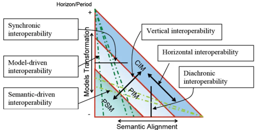
In (Panetto 2007) Panetto propose a maturity level, with six kinds interoperability solutions, represented in Figure 3-5:
Figure 3-5 - Interoperability Classification Framework (Panetto 2007)
Synchronic - Are issues where applications exchange models defined by compatible languages (the same syntax) but with different semantics, in a synchronous way;
Model-driven – This level is about technologies (or standards) to solve model syntactic transformations;
Semantic-driven – The developments where the semantic alignment is the main issue;
Vertical - when exchanging models from different abstraction levels, this exchange process from one application to another involves models transformations (syntactic) and semantic alignment (also called concept mapping);
Diachronic - Are issues when applications interoperate over time by exchanging models referring to different views of the same product. In this case, models have compatible semantics but need to be syntactically transformed before being exchanged. This allows streamlining model management and creating a true information management system.
3.1.6. Interoperability Practices Pyramid
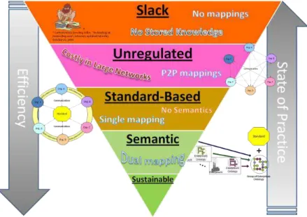
Finally, in 2009, Agostinho and Goncalves (Carlos Agostinho & Ricardo Jardim-Goncalves 2009) proposed another approach towards interoperability levels classification that divides the interoperability types into five layers, as presented in Figure 3-6:
Figure 3-6 - Interoperability Practices Layers (Carlos Agostinho & Ricardo Jardim-Goncalves 2009)
i. Slack interoperability – When there is no previous understanding between the sender and receiver. They have rudimentary communication methodologies with little support of advanced IS, e.g. ERP - Enterprise Resource Planning;
ii. Unregulated interoperability - Organisations work with peer-to-peer relationships, and maintain their own data format and business rules mediated by, as many mappings as the number of business partners;
iii. Standard-based interoperability - Several dedicated reference models covering many industrial areas are based on common collaboration models;
v. Sustainability Interoperability - The simplest way to describe the term "sustainability" in this context is that it is related to the aim of improving the quality of service by contributing to a more robust interoperability, avoiding excessive consumption of resources (e.g. man-power and time), when the dynamicity of system and networks causes harmonization breaking. It is a novel concept whose objectives are to reconcile the economics interests ensuring that network maximizes its efficiency by remaining interoperable at most times in any of the 3 previous levels (exception for slack interoperability).
3.1.7. Outlook in IL & ML
All the presented interoperability layers and maturity levels have the purpose to evaluate the interoperability status inside an organisation or specific system or network. It is relevant to know, in terms of interoperability, the position one is in, so that it can improve and become more efficient when exchanging information with its business partners. This thesis can be a facilitator for companies to improve their systems.
To complement that, some of the technologies mentioned in the many maturity topics have been further evaluated (e.g. MDI) and presented in the following sections, since they could be used for implementation purposes. Panetto (Panetto 2007) described a maturity level that recognizes the Model-Driven Interoperability (MDI) method as a major enabler for enterprise interoperability. Due to its great potentialities, it was decided to it would be a subject for study, to verify whether it is relevant to this work. Moreover, the EIF suggests a level that uses a semantic interoperability, which also has many implications in today’s systems, thus it was decided to contemplate that technology in section 3.3. Finally it was also considered important to look upon the model morphisms (MoMo) used in the work of Agostinho and Jardim-Goncalves (Carlos Agostinho & Ricardo Jardim-Goncalves 2009). In section 3.4, the MoMo concept is explained and in section 3.5 the CAS-SIF framework is described since it is a clear advancement of the state of the art, and the maturity level where this thesis can be of more assistance.
3.2. Model-Driven Interoperability
The Interoperability or the ability of a system or a product to work with others systems is gaining an important position in our days, since the organizations applications and software systems need to be interoperable in order to achieve seamless business across organisational boundaries. In the last decades appear a lot of solutions to help to improve interoperability, however full interoperability is not still achieved (Bourey et al. 2007), (Elvesæter et al. 2006).
Several projects to provide a better way of addressing and solving interoperability issues using semantic annotation and ontology were created. ATHENA and INTEROP define an interoperability framework for MDD of enterprise applications and software systems to address interoperability (Xu et al. 2009).
3.2.1. Model-Driven Engineering
Model-Driven Engineering (MDE) also know as Model Driven Development (MDD) is described in (Hailpern & Tarr 2006) as a software-engineering approach consisting of the application of models and models technologies to raise the level of abstraction at which developers create and evolve software.
With the advantage of expressing the models using concepts that are much less bound to the underlying implementation technology and are closer to the problem domain relative to most popular programming languages. This makes the models easier to specify, understand, and maintain. Other advantages of MDE is the standardization, that provides better practices, enables and encourages reuse, and facilitates interworking between complementary tools, and the programs are automatically generated from their corresponding models. And the most important issue that the MDE help is that it tools can perform a model checking that can detect and prevent many errors early in the life cycle (Bran Selic 2003), (Schmidt 2006).
Since the 1980s there is the attempt to create technologies that further elevates the level of abstraction used to develop software. Several attempts were made to create and implement a software engineering to help in this matter, but for different reasons none of them were widely adopted in practice. Using that past experience, the existing and emerging MDE technologies learned the lesson and developed higher-level platform and language abstractions (Schmidt 2006).
3.2.2. Model-Driven Architecture
The OMG introduced the Model-Driven Architecture (MDA) that was created with the intention to support the MDE in the specification of software systems based on a model transformation concept, and with the ability to address the complete development lifecycle, covering analysis and design, programming, testing, component assembly as well as deployment and maintenance. It was created with the objective to accomplish three main goals; portability, interoperability and reusability (ATHENA 2010), (Truyen 2006), (Petzmann et al. 2007).
With these in mind, we can say that one of the great advantages of the MDA is the standardized techniques that are used, like the Unified Modelling Language (UML), the Meta Object Facility (MOF), the XML Metadata Interchange (XMI) and the Common Warehouse Meta Model (CWM) (Truyen 2006), (Petzmann et al. 2007).