TO SUSTAINABLE ENGINEERING
Günther Seliger Sebastian Kernbaum Marco Zettl Institute for Machine Tools and Factory Management, University Berlin,
Pascalstr. 8-9,10587 Berlin, Germany, e-mail: [email protected], [email protected], [email protected]
INVITED PAPER
Abstract
Increasing use of resources by an increasing population with unequally distributed wealth make sustainability an urgent topic to pay attention to. A reference model for sustainability in engineering is presented referring to education and research, management, technology, processes and products as the relevant issues for a global change to sustai-nability. The European environmental laws for sustainable development are an attempt to cope with this challenge by legislative means. The provocative reality of practical implementation in dealing with electric and electronic products after their usage phases in Europe is illustrated. Laboratory developments in disassembly and testing demonstrate the feasibility of remanufacturing. In addition, approaches to increase the efficiency of remanufacturing by improving the product design are introduced.
Keywords: sustainability, engineering, remanufacturing, design for remanufacturing, modularity. v.13, n.3, p.367-384, set.-dez. 2006
1. Introduction
Sustainability is directed to enhance human living standards by harmonizing ecological, economical and socio-political needs while considering the availability of natural resources and ecosystems for future genera-tions. More than half of global value creation of today is achieved by less than one tenth of the global population. A sustainable political, economical and social stability can only be achieved if mankind is able to create jobs worldwide and not only in the irst world, as well as liv-ing conditions of human dignity.
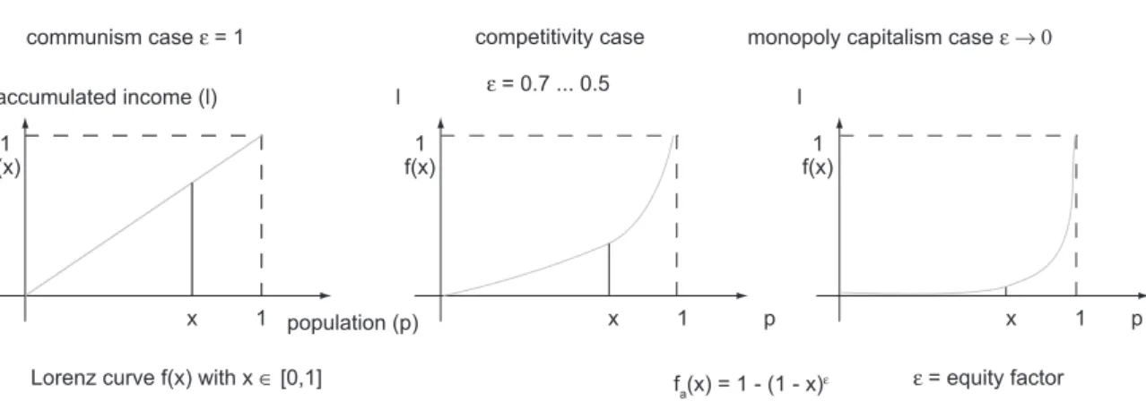
Human creative imagination, knowledge, experience, skills and initiative by entrepreneurial action coin our living conditions. Overcoming poverty requires a mini-mum of resources, abilities and qualiications provided for everyone in the world to take initiative for value add-ing activities. An equal level of wealth for everyone with hardly any differences in people’s living conditions takes
away incentives for useful engagement. The accumulated income earned by a population in a community from the poorest to the richest member is described by the Lorenz curve. The equity factor relates individual welfare to overall equity (Figure 1).
1.1 Sustainable engineering
Sustainability is a task, which cannot be addressed only by individuals, single companies or single countries. Sus-tainability is rather an all-embracing, cross-sectional task including aspects of each engineering discipline, which have to be addressed on a global scale. From this point of view, the idea of sustainability has been interpreted with respect to engineering science within the Collabora-tive Research Center 281 on Disassembly Factories for the Recovery of Resources in Product and Material Cy-cles funded by the German National Science Foundation (DFG) at the Technical University of Berlin (TUB).
Sustainable Engineering can be deined as the applica-tion of scientiic and technical knowledge to satisfy hu-man needs in different societal frames without compro-mising the ability of future generations to meet their own needs. To achieve this goal, scientists and engineers co-operate in international and multidisciplinary groups and organizations. They use their imagination, judgement and take initiative to apply science, technologies and practical experience to shape competitive processes and products. Management guides the creation, application and
evalu-ation of science, technology, processes, and products, as well as the dissemination of knowledge.
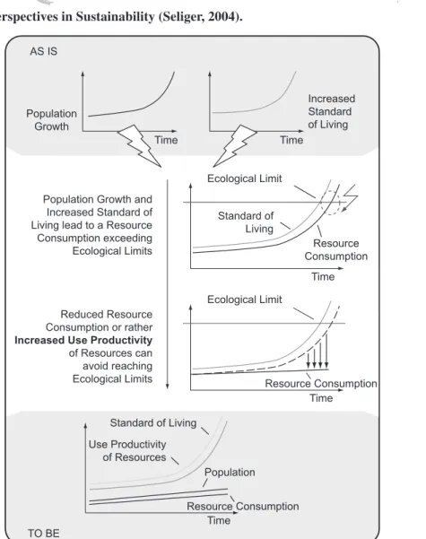
In Figure 3, the engineering perspectives in sustain-ability are illustrated, whereby human needs are repre-sented as the MASLOW pyramid spanning all societies (Maslow, 1999). The different colored columns between human needs and the available resources describe the dis-similarity of conditions of the global society. Engineer-ing challenges are the design of products and processes with improved usefulness and less environmental harm. Technology interpreted as science systematically exploit-ed for useful purposes offers huge potentials to contrib-ute. Technology enables processes to transform natural resources into products to meet human needs. The inter-action between research and education imposes dynam-ics on how creative solutions are developed for relevant tasks.
1.2 Resource productivity
In order to achieve the ambitious goals of sustainabil-ity, a paradigm change in applying engineering has to be performed. Hereby, increasing the use of productivity of resources has to be investigated in order to satisfy human needs of the current and future generation without ex-ceeding the ecological limits of the planet. Means of this approach are, e.g. expanding the life time of products, circulating resources, and distributed use of products. In Figure 4, the relation between resource productivity, standard of living, resource consumption and ecological limits are illustrated.
The question arises, which forces, e.g. legislation, en-trepreneurial initiative or technological innovation are capable of reducing resource consumption or rather in-creasing resource productivity to avoid exceeding eco-logical limits. European legislation is analyzed regarding its effectiveness to cope with this challenge.
The following analysis is restricted to electric and electronic goods, because especially these products have a large impact on the environment. In fact, recent studies communism case = 1
accumulated income (l)
1 f(x)
1 f(x)
fa(x) = 1 - (1 - x) 1 f(x)
x 1 population (p) x 1 x 1
Lorenz curve f(x) with x [0,1]
= 0.7 ... 0.5
= equity factor competitivity case monopoly capitalism case
l l
p p
Figure 1. Lorenz curve and equity factor: quantitative instrument for describing the inequality in a society (Radermacher, 2002).
EU (25) World
0.68 - 0.50 < 0.25
but EU (15)
N° 1 in South America
N° 1 in Africa
N° 1 in Asia
0.46
0.44
0.44
0.46
0.62
0.55
0.28 0.27
N° 1 in the World
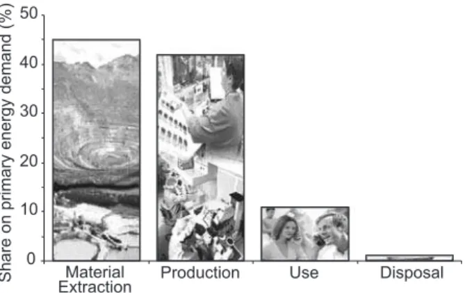
indicate that the major environmental impacts throughout the life cycle of electric and electronic equipment (EEE) occur in the material extraction and production stages
(Figure 5). For example, it has been shown that the pro-duction of a single microchip with a surface of 2.7 cm²
and a weight of 2 g consumes about 32 litres of water, Human Needs - Maslow Pyramid
Societal F al Frame
gement
socio-policy
socie-policy ecology ecology
Research Education Research Education
Societal Frame
economy sociopolicy economy
nology
Management Managem
Technology Technology
Process
rocess Process
Product
roduct Product
Natural Resources
AS IS
TO BE
Population Growth and Increased Standard of Living lead to a Resource Consumption exceeding Ecological Limits
Reduced Resource Consumption or rather Increased Use Productivity of Resources can avoid reaching Ecological Limits
Time Time Ecological Limit
Ecological Limit
Resource Consumption Resource Consumption Population
Growth
Time Time
Increased Standard of Living
Standard of Living
Time
Resource Consumption Standard of Living
Population Use Productivity
of Resources
Figure 3. Engineering perspectives in Sustainability (Seliger, 2004).
1.6 litres of fossil fuel, and 41 MJ of energy (Williams et al., 2002). Keeping in mind that many of the EEE, e.g. mobile tele-phones, are produced in large produc-tion volumes and are characterized by short time scales of technological and stylistic obsolescence the impact is multiplied respectively.
1.3 European legislation – is it effective?
On February 24, 1997 the European Council presented a resolution on a community strategy for waste manage-ment in the European Union (EU). The resolution insisted “... on the need for promoting waste recovery with a view to reducing the quantity of waste for disposal and sav-ing natural resources, in particular by reuse, recyclsav-ing, composting and recovering energy from waste”. It was recognized that the “... choice of options in any particular case must have regard to environmental and economic ef-fects but that until scientiic and technological progress is made and life-cycle analyses are further developed, reuse and material recovery should be considered preferable where and in so far as they are the best environmental options.” (The European..., 2002).
Based on this resolution, the European Parliament published the directive on waste electrical and electronic equipment (The European..., 2002) on January 27th, 2003
(WEEE) to specify and harmonize EEE shall be collected and treated at their end-of-life. The concept of producer responsibility forms the quintessence of the directive. The producer is responsible for inancing the collection from collection facilities, as well as the treatment of recovery and disposal of WEEE. He should be allowed to choose to fulill this obligation either individually or by joining a collective initiative. Furthermore, he shall provide a i-nancial guarantee to prevent costs for the management of WEEE from orphan products.
EU member states were obliged to bring into force the laws, regulations and administrative provisions necessary to comply with the directive on WEEE. A comparison of
the transposition of the directive in EC member states is well described in a frequently updated report published by Perchards (2005). In Germany, for instance, the Elec-trical and Electronic Equipment Act (ElektroG, German Bundesrat..., 2005) was adopted by the German Bun-desrat and brought into force on March 23, 2005, oblig-ing producers to start collectoblig-ing and treatoblig-ing commercial-ized EEE beginning on March 24, 2006.
To understand the effectiveness of the directive one has to understand the meaning of the term ´waste`. In Ger-many, waste is deined in the German Closed Substance Cycle and Waste Management Act (KrW-/AbfG) from 1994 (German Bundesrat..., 1994). According to § 3 Abs. 4 KrW-/AbfG waste comprises all movable property in the categories speciied in the law which the holder dis-cards, or intends or is required to discard. The holder must discard movable property when such property is no longer used in keeping with its original purpose, and when, due to its speciic state, it could endanger, either in the present or the future, the public interest, especially the environment.
In the context of the directive on WEEE, the speciic state of the property addresses the integrity and func-tional capability of EEE. If declared funcfunc-tional neither KrW-/AbfG nor ElektroG need to be applied enabling for the equipment’s free movement within and to des-tinations outside of the country. On the one hand, this can enable companies to re-market valuable equipment, e.g. IT equipment, into markets with high demand, e.g. in Eastern Europe or Africa. On the other hand, it leaves a door open for companies to bypass legislation.
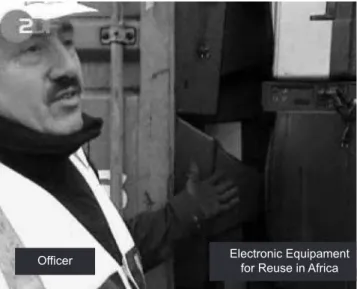
In Germany today, the temptation of abusive interpreta-tion of legislainterpreta-tion is growing for producers and recyclers as well. Even when collected as waste, a product can be declared functional and then be treated as a normal com-mercial asset thereafter. Public authorities do not have suficient personnel at their disposal to inspect all cross-border and oversea shipments of WEEE (ZDF..., 2006). It is at least questionable whether waste can be monitored and accounted for if producers implement individual col-lection and treatment schemes in cooperation with recy-clers without proper inspections. False declaration of non-functional equipment can help to reduce treatment and disposal cost and thus bypass producers´ responsibilities.
To avoid the environmentally harmful export of WEEE, stricter inspections are required but not sufi-cient. Recyclers and re-marketing companies must be en-abled to beneit from the opportunities in remarketing of functional equipment and components without the need of exporting waste.
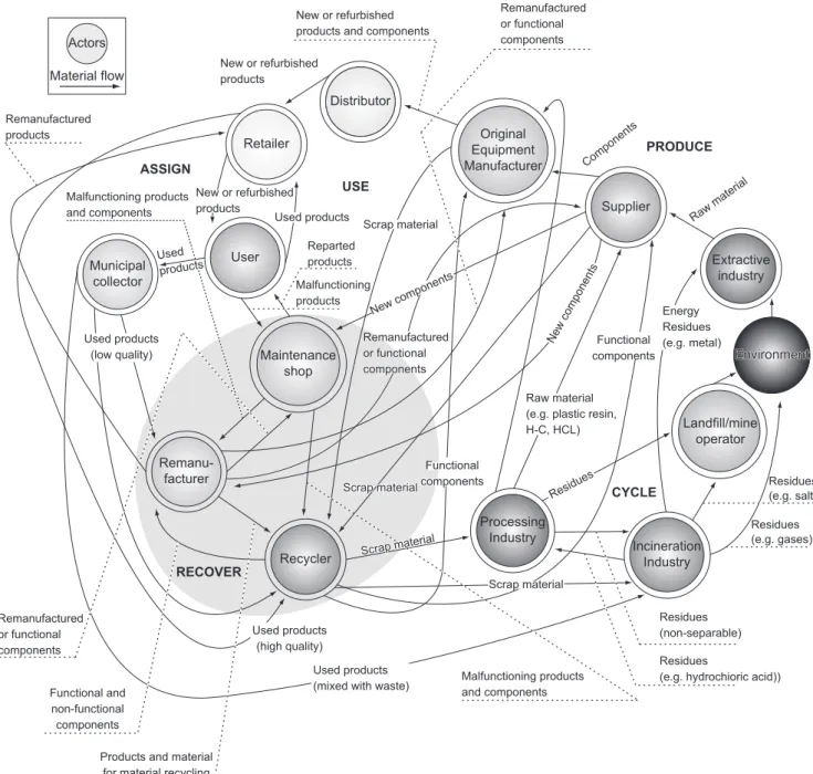
In Figure 6, the complexity regarding market actors and relationships that need to be dealt within European legis-lation on electronic waste is depicted. Figure 7 shows the
Share on primary energy demand (%)
50
40
30
20
10
0
Material
Extraction Production Use Disposal
provocative reality of exporting harmful non-functional electronic waste in containers via the Hamburg harbour. Oficials neither have suficient staff at their disposal, or the qualiications to test equipment in order to avoid il-legal exports.
1.4 Remanufacturing vs. Recycling
To investigate the relative environmental emissions as-sociated with recycling vs. remanufacturing, a Life Cycle Assessment (LCA) was conducted exemplarily for a mo-bile tele-phone. The results of the investigation showed as expected that mobile tele-phone production accounts for almost all of the non-energy related emissions in the
life cycle. It was also found that the integrated circuits, display modules and main printed circuit boards account-ed for nearly three-quarters of the energy consumaccount-ed in the production phase. Not including integrated circuits manufacturing, the production stage itself consumed ap-proximately 250 MJ of energy, which was over two times the estimated amount of energy consumed by the normal use of the mobile tele-phone over two years (Guenther et al., 2003).
In Figure 8 the production, use and EoL energy con-sumption of two identical mobile tele-phones in the fol-lowing three scenarios are illustrated: 1) both phones are manufactured and disposed at landills without recycling Material flow
Environment Actors
Retailer
Distributor
Original Equipment Manufacturer
Supplier
Extractive industry
Landfill/mine operator
Incineration Industry Processing
Industry Recycler
Remanu-facturer Municipal
collector
User
Maintenance shop
Products and material for material recycling Remanufactured
or functional components
Remanufactured or functional components
Remanufactured or functional components
Malfunctioning products and components Malfunctioning products
and components
Functional and non-functional components
Used products (high quality) Used products
(low quality) Remanufactured
products
Used products (mixed with waste)
Scrap material Scrap material
Scrap material
Scrap material
Functional components
Functional components
New components New components
New or refurbished products
New or refurbished products
Used products
Raw material (e.g. plastic resin, H-C, HCL)
Residues
Residues (non-separable)
Residues
(e.g. hydrochioric acid)) Residues (e.g. salt) Energy
Residues (e.g. metal)
Residues (e.g. gases) Raw material
Components New or refurbished
products and components
RECOVER
CYCLE PRODUCE ASSIGN
USE
Reparted products
Malfunctioning products
Used products
or remanufacturing, 2) both phones are manufactured and completely recycled (even though 100% recycling is nei-ther economically nor technically feasible), and 3) one phone is manufactured as-new, and the other identical phone is restored as-new from a discarded phone of the same model. The remanufacturing pathway has by far the least energy consumption. This is because the remanu-facturing pathway, unlike recycling, avoids repeating
Figure 7. Hamburg Harbour (ZDF..., 2006).
0 100 200 300 400 500 600 700
0 5 10 15 20 25 30 35 40 45
Global Warming Potential (GWP) Energy Consumption
MJ/Phone
Kg CO
2
Equivalent/Phone
Landfill Material Recycling Remanufacturing Landfill Material Recycling Remanufacturing
Material Extraction Production Usage End-of-Life - 140
- 130
- 7
- 8
Savings 15 kg CO2
~
9 months bonding capacity of average tree Savings
- 270 MJ ~
10 days energy consumption of average German household
Figure 8. LCA results for two life cycles of a product (Guenther et al., 2003).
manufacturing steps with characteristically high energy consumption and environmental emissions. The results indicate that the difference between land illing and re-manufacturing a mobile tele-phone represents approxi-mately 10 days of energy consumption for the average German household and 9 months of CO2 sequestration potential for an average tree (Guenther et al., 2003).
Enabling technologies for suficient remanufacturing are eficient remanufacturing processes and advanced product design using modularization techniques. Both challenges are described below. For remanufacturing processes, disassembly and testing are described in the example of LCD (Liquid Crystal Display) monitors. The improvement of the product design to increase the efi-ciency of remanufacturing is discussed in the example of a mobile tele-phone.
2. Efficient remanufacturing processes
Remanufacturing is already a proitable business ield. In fact, companies in Europe and North America are making signiicant proits by selling remanufactured products and components, e.g. mobile tele-phones and automobile components, mainly in markets of emerging countries (Skerlos et al., 2004). However the potential of remanufacturing is not fully exploited yet. Complex Electronic Equipamentand manual processes, various product models, missing product information, high spare-part costs, quality prob-lems as well as technological and stylistic obsolescence are making remanufacturing of many products unproit-able. An analysis of cost structures in the remanufactur-ing industry quickly revealed the major cost drivers: ac-quisition of cosmetic parts, manual sorting, disassembly and reassembly, as well as manual testing of functionality (Seliger et al., 2003).
2.1 LCD monitor keyfacts
The remarketing of used lat screen desktop monitors is evolving into a proitable market segment. Demand for used or non-functional monitors is growing especially in Eastern European countries and cannot be covered by End-of-Life (EoL) products, yet. Non-functional phase-out models are often sold to repair-shops in Eastern Euro-pean countries, which is often associated with improper EoL treatment of non-reusable components. To avoid negative environmental impacts caused by today’s prac-tice in demand markets with slack environmental regula-tions, clean remanufacturing activities must be initiated at the returned product’s origin.
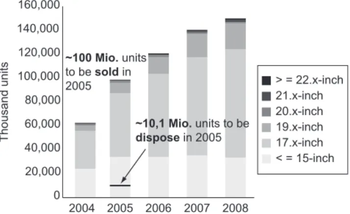
The demand for lat screen monitors today is grow-ing more. Used monitors are hardly available due to the low market penetration. In 2005 alone, about 137 Mio. desktop CRT (Cathod Ray Tube) and LCD monitors are expected to be sold (Figure 9). With 97 Mio. sold LCD monitors, their market share will reach about 71% (Alex-ander, 2004).
To estimate the return volume of used monitors that are to be disposed in 2005, one can assume the average monitor’s usage time being approximately 4 years, i.e., considering the sales volume of 2001. In that year, about 100 Mio. desktop monitors were sold and the AMLCD monitor’s market share was only 16%, i.e., 16 Mio. units. According to a US National Safety Council (1999) report approximately 45% of computers and peripherals are
be-ing used for a second time, i.e. 55%, or 8.8 Mio AMLCD monitors are disposed. In addition to this, one needs to consider those monitors that were used more than once, i.e. those that will return in 2005, but were sold before 2001. According to NSC (1999) the average period for second usage is 2.5 years, i.e., 45% of monitors sold be-tween mid 1998 and mid 1999 are used until 2005. With 1.3 Mio. AMLCD monitors sold in 1998 and 4.5 Mio. in 1999 [18] one can estimate the number of units to be dis-posed in 2005 form this period with 1.3 Mio. [(0.5*1.3 + 0.5*4.5)*0.45], resulting in a total of 10.1 Mio. AMLCD desktop monitors to be disposed worldwide in 2005.
Prices for used and non-functional 15”-18” monitors with control failures from private users – determined via the online market place eBay – usually range from € 40 to approximately€ 110, as long as the LCD panel glass is not broken. Defective monitors from leasing re-turns collected by larger IT-remarketing companies from institutional users are frequently exported to Eastern Eu-rope, where high demand meets cheap labor. An adequate EoL treatment of these monitors is at least very question-able.
From an ecological point of view, the shift from CRT to AMLCD technology can be considered a step towards sustainable development in the information and telecom-munication sector, if monitors are treated properly at their EoL. A Life Cycle Assessment of desktop compu-ter displays conducted by the University of Tennessee in 2001 compares the environmental and health impacts of AMLCD and CRT technologies (University of Tennes-see, 2001). As an example, AMLCD manufacturing is water and energy intensive. The manufacturing life stage, i.e., mainly the glass manufacturing process, accounts for over 75% of the renewable resource use. Due to the 60%-70% lower weight as compared to CRT displays, the natural resource consumption of AMLCD is signii-cantly lower. Energy consumption of AMLDC during use is also 60%-70% lower than for CRT displays.
2.2 Recycling keyfacts
In Germany today, only a few hundred tons of LCDs from lat screen monitors, including LCDs from televi-sion sets return for recycling. By 2012, the quantity of re-turned LCDs from these applications is expected to reach approximately 4,000 tons.
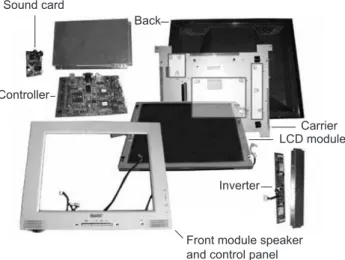
In Article 7 (2) of the European Directive on Waste Electric and Electronic Equipment (WEEE), the reuse and recycling targets for LCDs (group 3) are deined with 65% of the product’s weight (The European, 2002). Annex II of the WEEE obliges disassembly of all LCDs with a surface greater than 100 square centimeters and all those back-lighted with gas discharge lamps, prior to material recycling. Figure 10 depicts the elements of a LCD module.
160,000
140,000
120,000
100,000
80,000
60,000
40,000
20,000
0
2004 2005 2006 2007 2008 ~100 Mio. units
to be soldin 2005
~10,1 Mio. units to be dispose in 2005
> = 22.x-inch 21.x-inch 20.x-inch 19.x-inch 17.x-inch < = 15-inch
Thousand units
The most relevant recycling facts for lat screen moni-tors are summarized below. Data obtained by a literature review is complemented by the analysis of a 4 year old 15” lat screen monitor of a popular brand.
2.2.1 Liquid crystal display (LCD)
The LCD without printed circuit boards consists of approximately 87.2% glass, 12.7% foil and 0.1% liquid crystals (Martin et al., 2004). According to a statement by the German Federal Environmental Agency concern-ing the ecotoxicology of liquid crystals in liquid crystal displays, LCDs do not require special disposal, due to the content of liquid crystals (Ecotoxicology..., 2000)
Available and economically proitable recycling proc-esses use LCD’s glass as surrogates, e.g., instead of quarry sand in steel smelting processes, and plastics, i.e. foils, as an energy source for the smelting process (Martin et al., 2004). Recycling technologies for the recovery of the glass fraction for reuse in LCD manufacturing are still in an experimental state (Behrendt and Erdmann, 2003)
2.2.2 Cold cathode fluorescence
lamps (CCFLs)
CCFL contain small quantities of mercury and re-quire special treatment. CCFLs must be disassembled from the LCD module. Following the prognosis of the IZT (Behrendt and Erdmann, 2003) between 290 kg and 480 kg mercury will have to be disposed for all 80 Mio. lat screen monitors that will be in use by the year 2010.
2.2.3 Printed circuit boards (PCBs)
Due to the mandatory disassembly and separate treat-ment of LCDs, printed circuit boards need to be sepa-rated from the LCD’s glass and foil compound, usually by means of destructive disassembly.
2.2.4 Plastics
For the lat screen monitors analyzed, halogen free, i.e., bromide and chloride free plastics, e.g. PC + ABS -FR(40) or PC - FR(4), and acrylic glass were found. If separated properly, these plastics can be recycled for
re-use in similar applications.
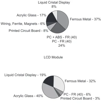
Figure 11 depicts the relative distribution of material fractions for an analyzed 15” LCD module (1790 grams) and the lat screen monitor without stand (4,070 grams) including the LCD module, as depicted in Figure 11. The achievement of material recycling targets of 65% or higher can be looked upon as being realistic, if material fractions are separated before recycling. With 78% of the monitor’s weight being perfectly separable ferrous metal, and plastic components, targets can be achieved even ne-glecting the glass and copper fractions from LCDs, re-spectively PCBs and wiring.
Extending the usage phase of lat screen monitors be-yond today’s average of four years is ecologically rea-sonable, due to the highly energy intensive production of LCDs and PCBs. Whether non-functional monitors can be prepared for another usage cycle economically de-pends on the costs for adequate take back, identiication, testing, disassembly, spare part procurement and re-dis-tribution. By means of a disassembly analysis, compo-nents suitable for reuse and the necessary disassembly effort are identiied.
2.3 Remanufacturing challenges
With a predicted 90% penetration of the monitor mar-ket with lat screen technology by 2010, product returns will be suficient to develop remanufacturing activities on a large scale. The main challenge, as in most
remanu-Two back frames Reflection foil Light guide
Prim foil Diffusor foil Housing for CCFL and LCD LCD and printed circuit board
Front frame Cold cathode
fluorescent lamp
Figure 10. Components of a LCD module.
Monitor without Stand
Liquid Cristal Display 8%
Acrylic Glass - 17%
Wiring, Ferrite, Magnets - 6%
Printed Circuit Board - 8%
PC + ABS - FR (40) PC - FR (40)
24%
Ferrous Metal - 37%
LCD Module
Liquid Cristal Display - 19%
Acrylic Glass - 40%
Printed Circuit Board - 3% PC - FR (40) - 6%
Ferrous Metal - 32%
facturing activities, is the handling of uncertainty regard-ing time, quality, quantity and place of product returns that affects collection, testing, disassembly, reassembly and the warehousing of spare parts likewise.
2.3.1 Collection
Today, IT equipment returns from leasing contracts are frequently collected by IT remarketing companies. Due to the low market penetration of lat screen monitors, col-lection from private households is still uncommon. Fu-ture collection using today’s municipal collection hubs is unlikely to guarantee an undamaged take back of lat screen monitors. To obtain access to product returns from private households, new take back models, e.g. charity recycling (Seliger et al., 2003), are required. Due to the dimension and weight of monitors, as compared to mo-bile phones, collection using the postal service is rather unlikely due to the high costs involved.
2.3.2 Disassembly
A disassembly analysis was conducted for 17 different lat screen monitors for module level (Figure 12).
Non-destructive disassembly of beyond warranty and non-functional, e.g. broken LCD modules are usu-ally economicusu-ally unfeasible and the LCD module is the monitor’s primary value. Advanced repair processes, e.g. disassembly of tape adhesive bonding (TAB) for the re-covery of driver tabs or the replacement of polarizers are predominantly applied during warranty or for highly in-tegrated LCD modules, e.g., notebooks or industrial con-trol panels. Being mandatory by law (The European..., 2002), the disassembly of LCDs from LCD modules is usually carried out destructively. All relevant com-ponents, i.e., frame, housing, LCD, foils, CCFLs, light guide and PCBs can be separated within approximately one minute.
Non-destructive disassembly of the monitor to module level is the prerequisite to enable the majority of remanu-facturing processes to be carried out. The most common repair option for the LCD module is the replacement of CCFLs. Therefore, from now on, CCFLs are deined as a module of the lat screen monitor. Other common repair options for the LCD monitor include the replacement of faulty electronic components, as well as mechanical components such as plugs.
For a systematic evaluation of the monitor’s relevant disassembly properties, the analysis was documented by means of a morphological box. To obtain comparable re-sults regarding the disassembly effort required, a Method Time Measurement (MTM) analysis was conducted for all 17 monitor models. The disassembly times depend-ing on monitor design range from 3.6 to 8.7 minutes and the quantity of screws used from 33 to 108 units. Disas-sembly properties and MTM results were summarized in Franke et al., 2005; 2006.
Particularly important for cost eficient disassembly is the provision of a suitable disassembly plan under con-sideration of the acquired test results for each product. A certain order of disassembly steps is usually predeined by the product design. Automation of selected disassem-bly, i.e. mainly unscrewing processes, can be an option once higher quantities of used lat screen monitors are available.
Based on the disassembly analysis of 17 monitor mod-els, basic restraints regarding the automation of disas-sembly operations were identiied as follows:
• very strong snap its in housings parts due to the strong release torques required,
• stands mounted to the monitor’s inside,
• integrated video or power supply cables requiring man-ual disassembly of the back housing, and
• electronic components mounted on the top and the bottom of the carrier, needing additional handling of the carrier. The monitors selected for hybrid disassembly of-fer weak housing snap its, externally mounted monitor stands, externally removable cables and electronic com-ponents mounted to one side of the carrier.
A prototypical hybrid disassembly system with one automated and one manual workplace connected by three square conveyor blocks was carried out. A 4-axis Selec-tive Compliant Articulated/Assembly Robot Arm (Scara) was applied for unscrewing and handling operations. A manual workplace, originally used for manual testing of mobile phones, was adapted for manual disassembly and reassembly operations and integrated in the system. The system can be extended to one more automated and ive more manual workplaces to accommodate further disas-sembly, as well as testing and reassembly operations. Sound card
Back
Controller
Front module speaker and control panel
Inverter
LCD module Carrier
At the manual workplace, the monitor is positioned on the work piece carrier. Large monitor stands are disas-sembled manually and small ones remain mounted to the back housing as long as they do not interfere with the ac-cessibility of joining elements. The monitor is transferred to the automated disassembly workplace (Figure 13). A suction gripper is used to pick up the monitor and position it on the pneumatic clamping device. External screws, the monitor back housing and internal components are removed. Metal covers, printed wiring boards and cable connectors are removed respectively disconnected using a two-inger gripper. In case a process fails, the monitor is forwarded to the manual workplace.
The material low in the above described disassembly system is physically carried out by means of a conveyor
system and all drives, sensors and actuators are operated using a modern control system.
An eficient use of this equipment requires a compu-ter aided planning approach, which can be supported by many simulation tools (Franke and Kernbaum, 2005).
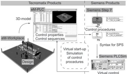
In the irst step, a 3-D model of the system was mod-eled using eM-Workplace. Conveyors, sensors, actuators and pallets are represented graphically without logic. In the second step, the model is extended by means of con-trol functions, e.g. the functionality of an optical sensor used to activate a mechanical stopper as a result of the detection of a moving pallet. In the third step eM-PLC is applied to generate operation sequences to be used with programmable logic controllers (PLC).
These control sequences can be represented in a user friendly manner and transformed into PLC commands using STEP 7. Based on the real PLC, a virtual PLC can be conigured and tested using these commands. Using the virtual PLC, the system can be tested for logic faults in a short time and without the need of real material movement. Therefore, the virtual start-up as illustrated in Figure 14 can help reduce real start-up time and help avoid start-up problems.
2.3.3 Testing
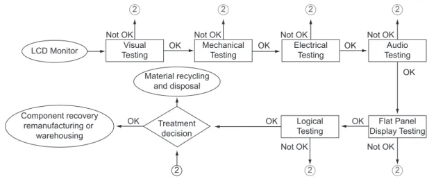
Testing is to determine, whether a testing object is ful-illing one or more agreed, required or expected terms, especially whether given error margins and tolerances were met. Electric or electronic devices are basically tested when assembled – alternatively, testing can be ap-plied to components after disassembly.
Testing methods for assembled LCD monitors were systematized in six categories, where order is derived from the expected time and cost effort for testing. The testing procedure starts with the process that has the low-est effort and is shown in Figure 15. If an error occurs when the testing procedure is being carried out in one of the testing processes, the next testing process cannot (1) Positioning of the monitor
(2,3) Clamping the monitor (4,5) Opening the housing (6) Unscrewing of circuit board
1 2 3
4 5 6
7 8 9
F
(7) Decoupling of cable connector (8,9) Handling of circuit boards
Figure 13. Automated disassembly process.
Tecnomatix Products Siemens Products eM-PLC
3D-model
eM-Workplace Control propertiesControl sequences
Virtual start-up Simulation
of control procedures
Virtual control Siemens PLCSim Control procedures
Syntax for SPS Siemens Step 7
Design
be initiated as well as options of destructive and non-de-structive disassembly results.
Detailed inspection instructions and inspection records, as well as low charts for visualization were de-veloped for the considered testing methods, which will be explained exemplarily below.
2.3.3.1 Visual testing
The visual testing of LCD monitors comprises inspec-tion of the front and back housing modules, operating controls, all electronic connectors (graphic, power sup-ply, sound I/O, possible USB connections), possible at-tached wires for the connection to PC’s, monitor stands and LCD modules. Observable errors are breakages, scratches or the absence of one or more element. For the better estimation of remanufacturing options, quality classes can be deined as given exemplarily in Table 1.
Cleaning before inspection and determination of sur-face quality can help to improve the rating process. No special equipment is necessary for visual testing except some cleaning tissues. Devices that pass the visual test are assigned to the mechanical test.
2.3.3.2 Mechanical testing
During the mechanical testing process, the connections of the electrical components controller (graphic, power and/or USB connectors), converter and sound card are tested with respect to mechanical damage. In the course of mechanical testing, power and data connections are established for subsequent tests.
2.3.3.3 Electrical testing
Backlight functionality and basic LCD-Module func-tionality are determined by means of a test signal in the course of electrical testing. Exemplary tests have shown that the test signal can be detected even without backlight functionality.
2.3.3.4 Audio testing
Speaker and sound card functionality are determined in what is denoted by acoustic testing. A faulty repro-duction of a standardized sound signal usually originates from either speaker or sound cards defects and requires testing components. Electric and acoustic testing requires a simple PC, only.
2.3.3.5 Display testing
The electronic testing of the LCD-Module requires a device to generate standardized test signals and to ana-lyse electric measurements. Damaged gate or data driver chips, as well as damaged TFT can be the cause of defec-tive pixel or sub-pixel. The standard ISO 13406-2 deines the quality criteria for pixel error tolerance. Limits for constantly bright or dark as well as defective sub pixels are deined. The standard ISO 13406-2 provides custom-ers and manufacturcustom-ers with a clearly deined and thus comparable warranty claim deinition, in which the pixel fault classes are given. As an example for a 15” LCD panel, a maximum of 4 defective sub pixels or 2 defec-tive bright or black pixels are accepted for category II, i.e., quality class A. Up to 500 defective sub pixels or 50 bright respectively, 150 dark pixels are considered as quality class B.
2 2
2
2
2 2
2
LCD Monitor
Component recovery remanufacturing or
warehousing
Not OK Not OK Not OK Not OK
Not OK Not OK
OK
OK OK OK
OK
OK OK
Visual Testing
Mechanical Testing
Electrical Testing
Audio Testing
Treatment decision
Logical Testing
Flat Panel Display Testing Material recycling
and disposal
Figure 15. Testing process chart.
Table 1. Quality classes for components.
Component Quality
Class C Class B Class A
Front housing module speakers and controls
Defective speakers or control
Scratched Housing
Unscratched Housing
Broken housing
Scratched Housing
Unscratched Housing
Test patterns generated by a personal computer (PC) or a “stand-alone-unit” as given in Figure 16 can be used to identify these defects manually by means of a visual test. Moreover, the “stand-alone-unit” can be used for electronic testing of the inverter board and digital inter-face of a disassembled LCD-Module.
Other defects caused by usage include scratched po-larizers, defective row or column controllers, defective TABs or drivers or aged color ilters. Table 2 summarizes the deined quality classes for LCD modules.
2.3.3.6 Logical testing
Logic testing comprised the options of monitor adjust-ments using the monitor’s panel and on-screen-display (OSD) as well adjustments carried out using the PC setup software. Examples are clock phase, contrast, and auto adjust (OSD) or frequency and resolution (software).
2.4 Electronic fault diagnosis of LCD
monitor components
The simple testing of the product’s functionality is usu-ally considered reasonable, as long as no security relevant functions are jeopardized. Functionality by itself does not ensure the faultlessness of the electronic component. An assignment of errors for components when failures are identiied can hardly be achieved. Disassembly for
component level enables extended testing and therefore the containment of failures. Intensive diagnoses under different environmental conditions using predetermined procedures are required when components are not only to be reused, but to be remanufactured to new products.
Different test methods for electronic components are applied in production processes. Table 3 shows applied methods comparing the contrasts. The test methods were analyzed and their applicability for remanufacturing evaluated.
Signature analysis was identiied as a suitable diag-nostic method, a diagdiag-nostic tool to examine critical per-formance parameters of subassemblies and components. Signatures of used parts are compared to those of new parts, respectively “good”-parts are compared to “bad”-parts. Signatures of standard electronic components are given in Figure 17.
Signature analysis was applied to basic electronic com-ponent. Figure 17 depicts the respective signatures for each basic component using a simple test setup including oscilloscope, frequency synthesizer, modiiable resistor and wires. Figure 18 presents the circuit diagram.
After validating the applicability of signature analysis for LCD monitor’s component testing with the simple test setup, professional signature analysis equipment includ-ing PC interface and software from Huntron (http://www. huntron.com, 2006) was applied. Figure 19 illustrates the test setup and an exemplarily application of signature analysis for a converter board.
Figure 20 depicts the deviation of signatures between a functional and a faulty converter board as tested and analyzed by means of the applied PC Software from Huntron.
Table 2. Standard components of the LCD monitor. Component
Class C
Quality
Class B Class A
Liquid Crystal Display Module
Glass substrate broken
Pixel defect category III or IV (ISO 13406-2)
Pixel defect category I or II (ISO 13406-2) Beyond category
IV (ISO 13406-2) Defective row or column controller
Scratched polarizer Defective contacts,
tape adhesive bonding (TAB) or data or gate driver
Aged color ilter
Cold Cathode Fluorescent Lamp (CCFL)
Broken Weak
emission
Bright
- Backlight
(on/off and light/dark) - Voltage and Amperage - Resolutions
- Automatical Test Pattern (Single colors, lines of columns)
Figure 16. “T-Drive” for LCD module testing.
resistive capacitive inductive semi-conducting
I
I
V R
Test object
Figure 17. Standard Signatures.
In the following, approaches to increase the eficiency of remanufacturing by improving the product design are introduced.
3. Design improvements for
efficient remanufacturing
Today’s industry is confronted with challenges to in-crease the proitability of remanufacturing. Most of these
challenges are caused by mainly high complexity of products, many product variants as well as technological and stylistic obsolescence. These challenges are contrib-uting to less proitability of remanufacturing processes, especially for mass products, e.g. lat screen monitors and mobile tele-phones.
Two parallel paths have been developed in order to cope with the described challenges. The paths are
exem-Table 3. Evaluation of testing methods.
Test method Advantages Disadvantages
Electrical Test Functional Test • Test of functionality of components and the whole
PCB;
• Test of programmed functionality;
• Identiication of dynamic and thermal failures.
• Requires Basic functionality;
• No identiication of missing condensers;
• Test under power →risk of
consecu-tive fault;
• Requires often complex test beds; • Identiication of failure effect; not
fail-ure cause
In-Circuit-Test • Test of components according to correct data;
po-larity; internal functionality; programmed func-tionality etc.;
• Results simple to interpret; • Power-off testing;
• Simple programming on component level; • High automation pot ential.
• No test of PCB functionality;
• Complex programming for bigger PCBs;
• No identiication of dynamic or ther-mal failures;
• Requires digital test patterns for IC’s; • Complex contacting (needle bed);
re-quires new needle beds after layout changes;
• Inlexible for repair services.
Boundary-Scan-Test
• Simple Contacting;
• Test of complex components (IC’s); • Power-off testing.
• No test of PCB functionality; • Complex programming;
• No identiication of dynamic or ther-mal failures.
Signature Analysis
• Identiication of typical production failures and de-fect components;
• No component library necessary; • Technology independent; • Power-off testing;
• Simple Programming („Good“-Signature).
• Restricted recognition of failures in component networks;
• No measurement of component data and tolerances;
• No identiication of dynamic or ther-mal failures;
• Requires interpretation of operator.
Optical Tests
Automatical-Optical Inspec-tion
• High automation potential;
• Character recognition → recognition of
compo-nents etc.
• Complex programming; • No test of PCB functionality; • No identiication of shorts below
com-ponents respectively inside the PCB.
Automatical-X-Ray Inspection
• Identiication of shorts below components respec-tively inside the PCB.
• Complex programming; • No test of PCB functionality;
• No recognition of wrong component data;
• Automatically picture evaluation often not possible;
plarily illustrated in the example of mobile tele-phones. The irst path, the reactive path was to develop a single lexible mobile tele-phone housing concept that would permit the inclusion of electronic components from a wide range of existing products. This concept was called the Mobile Tele-phone Housing Platform (MTHP). The feasibility of the MTHP concept has been demonstrated by a physical prototype, which was capable to incorpo-rate electronic components from at least three different mobile tele-phone models from the same Original Equip-ment Manufacturer (OEM) (Seliger et al., 2003). Advan-tageous of the concept is that it can be pursued by the remanufacturer themselves in order to decrease the cost for spare part acquisition respectively the acquisition of cosmetic parts, which are the important cost drivers by remanufacturing of mobile tele-phones.
3.1 Mobile tele-phone housing
platform (MTHP)
The MTHP, which is able to it electronic components from different cellular tele-phone models into single housing, enables the reduction of costs in remanufac-turing created by the need to purchase spare parts from
Original Equipment Manufacturers (OEMs). The MTHP approach also reduces the number of spare parts to be kept in an inventory.
The development of the MTHP concept has been de-veloped for speciic sub-classes of mobile tele-phones, since the actual number of mobile tele-phone variants available on the market was estimated to be several thou-sands considering only geometrical features. These vari-ants have been categorized in the following classes: can-dy-bar, lip and slide phones. To deine the scope of the project, mobile tele-phones available on the market were sorted according to their market share so that the MTHP could be targeted to mobile tele-phones with the highest second-hand market value.
Overall, three different MTHP designs were carried out. The irst generation MTHP was developed primarily to ad-dress the large variation in length of mobile tele-phones. All components except the speaker and the microphone are ixed in the back housing using a lexible foam mate-rial with useful heat transfer characteristics. The MTHP was developed without screw connections, using instead assembly and disassembly friendly snap-, clip- and press-it connections. After prototyping the MTHPs, press-it was clear that its advantage was its high lexibility in length and easy assembly and disassembly. However it was also evident that its weak point was the dificulty in aligning interior components and in its fragile structure.
To improve on the weak points of the irst MTHP de-sign, an enhanced second design was developed. The goal of high lexibility in length from the irst generation was abandoned in order to enhance the structural integrity of the MTHP. In this design, the speaker, microphone, and circuit board, as well as the lens and the keypad, are ixed in the front housing, while the remaining components are ixed in the back housing using high lexibility press-it and snap-it fasteners. The “one-size-snap-its-all” keypad was designed to work with each of the selected mobile tele-phones. It was presumed that alternative keypads could be offered for different cell phones. After prototyping this MTHP, it was found that structural strength, keypad lexibility, and assembly/disassembly-friendliness were its primary advan-tages. Its disadvantage was the inability to adjust length and its large number of parts (Seliger et al., 2003).
To achieve a more adaptable design with fewer parts, a third generation MTHP was conceived (Figure 21). The main characteristic of this MTHP is its frame tray, where all components are ixed in the proper orientation and location. Therefore the design of the housing com-ponents is completely independent from the layout of the electronic components. In this MHP, the circuit board is ixed with screws to increase its robustness to shock and vibration. The keypad is based on the same design as the second generation MTHP. The advantages of this Power supply of a LCD monitor Testing point of diode and coil
Signature of a semi-conducting and an inductive
component (diode and coil)
Testing workplace with signature analyses device ProTrack and PC
Figure 19. Application of signature analysis.
Figure 20. Deviation due to short circuit.
BAD-Signature
MTHP are its robust and lexible design, adaptability to customer needs, and “one-size-its-all” keypad solution. Its only weakness is its limited adaptability to phones of variable length. Therefore the MTHP size was classiied to different geometry (Skerlos et al., 2004).
However, the challenges which appeared when devel-oping the MTHP led to the second path, the proactive path. The second path was to improve the product design of a mobile tele-phone in order to increase its suitabil-ity for remanufacturing, which is also called Design for Remanufacturing (DfR). In applying DfR, the challenges of remanufacturing are already considered in the product development process. Modularity hereby, is one of the key elements to achieve this goal (Figure 22). The result of pursuing the second path is the Modular Mobile Tele-phone (MMT). However, this concept can only be carried out by the OEM.
3.2 Modularity: enabler for
efficient remanufacturing
Based on Göpfert, modularization can be deined as the grouping of functional carriers to physical and func-tional independent units or so called modules. This means that a module can fulill at least one function independ-ently without any additional component, e.g. power unit of a personal computer. Thereby the inner connections of modules are stronger than between modules. A vital ele-ment of physical independence is the design of disassem-bly and reassemdisassem-bly suitable module interfaces. Hereby, functions for material, signal and energy low should be integrated in the physical design of the module interface. Module interfaces can be divided into deinite, multiple and universal. The highest degree of independence is achieved by multiple and universal interfaces that allow an arbitrary exchange of the modules leading to a highly lexible product structure (Göpfert, 1998).
The standardization of modules and module interfaces is signiicant for the reuse of modules in different product generations and variations. In order to achieve function-al independency of a product, the carriers of functions have to be grouped appropriately. The groupings have to be carried out with respect to different competing goals along the product life cycle, which can be described as module drivers (Erixon, 1998).
3.3 Modular mobile tele-phone (MMT)
The pursued goal with the development of the MMT is to reduce costs throughout the product life cycle by means of standardization, modularization and platform development. Mass customization (MC) and postpone-ment are further aspects driving the developpostpone-ment of the MMT.
The MMT is characterized by standardized electronic modules and housing components, as well as form-spe-ciic modules allowing for quick assembly, disassembly and reassembly of the form-factor models: candy-bar, slide and lip phone. The main reasons for modulariza-tion are deined by means of so-called module drivers (Erixon, 1998).
Circuit Board Keypad Lens
Front Cover
Microphone Speaker Fixation
Speaker
Frame
CB Fixation (Screw)
Battery
Back Cover Speaker
Adaptation Processes
Upgrade Scale up Repair Harddrive
Upgrade CPU Upgrade
Add Soundcard
Adapted Desktop
Computer
Graphic Card Upgrade
Second Use Computer
Modular Desktop Computer First Use
Phase
Figure 21. Third generation of Modular Tele-phone Housing Platform (MTHP) (Skerlos et al., 2004).
The applied module drivers are:
• Product realization: Multiple use of existing technolo-gies/components/modules for different product vari-ants; parallel development of modules,
• Product development: Production and assembly (simple and standardized production processes and equipment), quality (separate tests of modules),
• Distribution: MC and postponement, • Product Use: Service; and
• End of life: Disassembly and reassembly (simple and standardized production processes and equipment), ad-aptation (upgrade, etc.).
Modularization of the mobile phone components ena-bles simple and fast assembly, disassembly and reassem-bly processes that allow for an easy module replacement, enlargement or reduction, as well as housing and form-factor change. Short development processes by parallel module development are followed by a long life cycle of the respective module, for instance by reuse. Further-more, it is possible to adjust the mobile phone to techni-cal innovations and individual customers’ needs. Thus, customers have the possibility of determining the con-iguration of their mobile phones by themselves and to select between different form factors. The inal assembly of the mobile phone modules and housing components can be carried out at the store by the staff or from the customer themselves (Seliger et al., 2006).
The MMT consists of one platform and ive housing components, as well as eleven modules (two optional modules, ive modules in different variants, three form-factor speciic modules and one standard module). These modules can be arranged in the three form-factors: can-dy-bar, lip and slide.
Beside the modules that are used for the candy-bar tele-phone, the modules Flip mechanism and 2nd Display are added for assembling the lip tele-phone. For the slide arrangement, a nearly invisible slide mechanism (instead of the lip mechanism) and a housing cover have to be subjoined. The mobile phone can be opened by sliding the top parts over the lower parts to uncover the numeri-cal keypad (Figure 23).
4. Summary and Outlook
Unequal distribution of wealth is still a major chal-lenge in the global community. The increase of standards of living for everyone could lead to a resource consump-tion that will exceed ecological limits. The increase of resource productivity can contribute to a shift from cra-dle-to-grave to cradle-to-cradle economy and therefore to sustainable resource consumption and consequently an increased standard of living and balanced distribution of wealth. Legislation can contribute to form paths for ac-tivities in sustainability. However, legislation should only set minimal social, labour and environmental standards without hindering entrepreneurial initiative and
techno-Display Module
Camera Module (2.1 Mega pixel)
Slide Module
Flip Module
Speaker
Lower Frame
Rechargeable Battery 2nd PCB
Module Function Keypad
Module Numeric Keypad
Printed Curcuit Board (PCB) -Platform
Mini-SD Card GPS-Module Upper Frame
Module Finger -Print Scanner Housing Components
logical innovation in a competitive environment. Europe-an legislation on WEEE cEurope-an be improved with respect to these requirements. As an example, illegal export, which is common practice to dispose of electrical and electronic waste, should be detained. Therefore, technical enablers are required to keep treatment and in particular remanu-facturing activities at the origin of product return. Disas-sembly and testing are the main drivers for environmental conscious remanufacturing. In the example of a Modular
Mobile Tele-phone Concept (MMT), it has been shown that modularity of products supports these activities.
Acknowledgments
We express our sincere thanks to the Deutsche For-schungsgemeinschaft (DFG) for inancing this research within the Collaborative Research Centre 281 on Disas-sembly Factories for the Recovery of Resources in Prod-uct and Material Cycles.
Bibliographical References
ALEXANDER, R. Worldwide Monitor Market Tracker. iS-upply, Stanford Resources. 3. quarter 2004.
BEHRENDT, S.; ERDMANN, L. Display-Märkte im Um-bruch – Neuorientierungen für Umweltschutzstrategien. Roadmap des IZT. Berlin 2003.
BASDERE, B. Beitrag zur Steigerung der Nutzenproduk-tivität von Ressourcen durch Anpassen von Mobiltele-fonen. Reihe Berichte aus dem Produktionstechnischen Zentrum Berlin, Berlin 2004.
DISPLAYSEARCH DELIVERS BREAKTHROUGH RE-PORT ON LCD MONITOR MARKET, 1999. Available at www.displaysearch.com/press/1999/120999.htm ERIXON, G. Modular Function Deployment – A Method
for Product Modularization. Doctoral dissertation, Royal University of Technology, Stockholm, Sweden, 1998. FRANKE, C.; KERNBAUM, S. Virtueller Inbetriebnahme
eines Aufarbeitungssystems für Flachbildschirme. In: FUTUR 1/2005 – Mitteilungen aus dem Produktion-stechnischen Zentrum Berlin, Berlin, April 2005
FRANKE, C.; SELIGER, G.; YAKUT, E. Mobile Phone Remanufacturing Program planning in Networks. In: Proceedings of the Global Conference on Sustainable Product Development and Life Cycle Engineering, uni-edition, Berlin, 2004, p. 187-190
FRANKE, C.; KERNBAUM, S.; SELIGER, G.: Remanu-facturing of Flat Screen Monitors – Economical and Technological Challenges until 2010 In: Proceedings of the 38th CIRP International Seminar on Manufacturing Systems (ISMS), Florianopolis, Brazil, May 2005 FRANKE, C.; KERNBAUM, S.; SELIGER, G.
Remanu-facturing of Flat Screen Monitors. In: Innovation in Life Cycle Engineering and Sustainable Development, Hrsg.: Brissaud, D., Tichkiewitch, S., Zwolinski, P., Springer, 2006, S. 139-152.
GERMAN BUNDESRAT: Gesetz über das Inverkehr-bringen, die Rücknahme und die umweltverträgliche
Entsorgung von Elektro- und Elektronikgeräten (Elektro- und Elektronikgerätegesetz – ElektroG). March 2005 GERMAN BUNDESRAT: Gesetz zur Förderung der
Krei-slaufwirtschaft und Sicherung der umweltverträglichen Beseitigung von Abfällen. September 1994.
GÖPFERT, J. Modulare Produktentwicklung - Zur gemein-samen Gestaltung von Technik und Organisation; Gabler Verlag/Deutscher Universitätsverlag; Wiesbaden, 1998 KÄMPKE, T.; PESTEL, R.; RADERMACHER, F. J.
Eu-ropean Journal of Law and Economics, v. 15, iss. 2, p. 129-163(35), Kluwer Academic Publishers, March, 2003.
MARTIN, R.; BECKER, W.; SIMON-HETTICH, B. Verw-ertungsverfahren für LC-Displays. In: Workshop Nach-haltigkeit als Chance und Herausforderung für Unterneh-men im Flachdisplaymarkt. Berlin, May 12 2004. MASLOW, ABRAHAM H.: Motivation und Persönlichkeit.
Reinbek, 1999.
NSC - National Safety Council. Electronic Product Recov-ery and Recycling Baseline Report: Recycling of Select-ed Electronic Products in the UnitSelect-ed States. Washington DC. May 1999.
PERCHARDS: Transposition of WEEE & RoHS Directives into national law of EU Member States* and correspond-ing industry activities – Summary of Perchards’ Quar-terly End-of-Life Policy Updates. April, 2005.
SCHMIDT-BLEEK, F. Wieviel Umwelt braucht der Men-sch? MIPS - Das Maß für ökologisches Wirtschaften, Birkhaeuser, 1993, English translation: The Fossil Mak-ers - Factor 10 and More, available at www.Factor10 In-stitute.org
SELIGER, G. Global Sustainability - A Future Scenario. In: Proceedings of the Global Conference on Sustainable Product Development and Life Cycle Engineering, Pub-lisher uni-edition, Berlin 2004, p. 29-35
SELIGER, G.; KERNBAUM, S.; ZETTL, M. Approaches for Sustainable Manufacturing. In: 7th. International Conference on. Frontiers of Design and Manufacturing, Guangzhou, p. 19-22, China, June 2006.
SELIGER, G.; BASDERE, B.; CIUPEK, M.; FRANKE, C. Contribution to Eficient Cellular Phone Remanufactur-ing. In: CIRP Seminar on Life Cycle Engineering, Co-penhagen. Denmark, May 2003.
SKERLOS, S. J.; ZETTL, M.; BASDERE, B.; SELIGER, G. Collaborative Development of Sustainable Strategies for the Reuse of Mobile Phones in a Global Educational Environment. In: Proceedings Global Conference on Sus-tainable Product Development and Life Cycle Engineer-ing, Berlin, Germany, 29.09 – 01.10.2004, S. 337-344. RADERMACHER, F. J. Balance oder Zerstörung.
Öko-soziale Marktwirtschaft als Schlüssel zu einer weltweiten
nachhaltigen Entwicklung. Österreichischer Agrarverlag Druck- und Verlagsges.m.b.H., 2002
THE EUROPEAN PARLIAMENT, THE COUNCIL: Di-rective of the European Parliament and of the Council on Waste from Electrical and Electronic Equipment (WEEE). Brussels, 2002
UMWELTBUNDESAMT: Ecotoxicology of Liquid Crys-tals in Liquid Crystal Displays. . 2000.
UNIVERSITY OF TENNESSEE 2001, University of Ten-nessee, US-Environmental Protection Agency, Desktop Computer Displays - A Life Cycle Assessment, 2003. Available at www.epa.gov.
WILLIAMS, E. D.; AYRES, U. A.; HELLER, M. “The 1,7 Kilogram Microchip: Energy and Material Use in the Production of Semiconductor Devices”, Journal of Environmental Science and Technology, v. 36, n. 24, p. 5504-5510, 2002.
ZDF: FRONTAL 21. 17. January 2006, http://www.huntron. com/. Last access: 31.01.2006
ABORDAGENS DE REMANUFATURA – UMA CONTRIBUIÇÃO PARA
ENGENHARIA SUSTENTÁVEL
Resumo
O crescente uso de recursos gerado pelo contínuo crescimento populacional inserido em um cenário de distribui-ção desigual de riqueza faz do termo sustentabilidade um tópico urgente para discussão. Neste artigo, apresenta-se um modelo de referência para sustentabilidade em engenharia que aborda questões relevantes para uma mudança global no caminho para a sustentabilidade, priorizando os seguintes elementos: educação e pesquisa; gestão, tec-nologia, processos e produtos. As leis ambientais da União Européia esforçam-se para tratar com responsabilidade esse desafio de desenvolvimento sustentável. A realidade de implementações práticas em consideração a produtos eletro-eletrônicos depois de sua fase de uso é ilustrada no artigo. Desenvolvimentos em laboratório de desmontagens e testes demonstram a viabilidade da remanufatura. Além disso, abordagens para aumentar a eficiência do processo de remanufatura a partir de melhorias no processo de desenvolvimento do produto são também sugeridas.