UNIVERSIDADE FEDERAL DO CEARÁ CENTRO DE TECNOLOGIA
DEPARTAMENTO DE ENGENHARIA METALÚRGICA E DE MATERIAIS
PROGRAMA DE PÓS-GRADUAÇÃO EM ENGENHARIA E CIÊNCIA DE
MATERIAIS
PAULO DEMÉTRIOS DA SILVA LIMA
TEXTURAL PROPERTIES STUDY OF Mg-Al LAYERED DOUBLE HYDROXIDES WITH DIFFERENT MOLAR RATIOS AND UPON
HYDROTHERMAL TREATMENTS
PAULO DEMÉTRIOS DA SILVA LIMA
TEXTURAL PROPERTIES STUDY OF Mg-Al LAYERED DOUBLE HYDROXIDE WITH DIFFERENT MOLAR RATIOS AND UPON
HYDROTHERMAL TREATMENTS
Tese apresentada ao Programa de Pós-Graduação em Engenharia e Ciência de Materiais da Universidade Federal do Ceará, como requisito parcial à obtenção do título de doutor em engenharia.e ciência dos materiais Área de concentração: materiais não metálicos.
Orientador: Prof. Dr. Ricardo Emílio Ferreira Quevedo Nogueira
Co-orientador: Prof. Dr. Sebastião Mardônio Pereira de Lucena.
PAULO DEMÉTRIOS DA SILVA LIMA
TEXTURAL PROPERTIES STUDY OF Mg-Al LAYERED DOUBLE HYDROXIDE WITH DIFFERENT MOLAR RATIOS AND UPON
HYDROTHERMAL TREATMENTS
Tese apresentada ao Programa de Pós-Graduação em Engenharia e Ciência de Materiais da Universidade Federal do Ceará, como requisito parcial à obtenção do título de doutor em engenharia e ciência dos materiais Área de concentração: materiais não metálicos.
A Deus
A minha mãe que me ensinou a trabalhar e estudar.
AGRADECIMENTOS
A Deus
A meus pais Raimundo Nonato Cardoso Lima, Albanisa da Silva Lima e Maria Zenete Silva de Oliveira.
A minhas filhas, Karina e Lara Lima, que sentiram minha ausência em várias noites e fins de semana isolado no escritório. O sentimento foi recíproco. Vocês são meu motivo de tanto trabalho e estudo.
A meus irmãos que sempre me apoiaram Claudia Cristina, Sérgio Ricardo e Antônio André e seus respectivos cônjuges: Kleber, Silvânia e Andrea.
Ao meu amigo Daniel Paula de Sousa que sempre estudou muito e valorizou os amigos que estudam.
Ao meu orientador Ricardo Emilio Ferreira Quevedo Nogueira pela paciência, ajuda constante e confiança.
Ao meu coorientador Sebastião Mardônio Pereira de Lucena que me vem orientando desde a graduação como aluno do PET, orientação em pesquisas no NUTEC, coorientação na pesquisa do mestrado e coorientação nessa pesquisa do doutorado. Meu muito obrigado por todos esses anos de muita paciência em suportar minhas teimosias.
Ao professor Dr. Sasaki que esmiuçou e levantou vários pontos falhos em minha tese. Obrigado por sua contribuição professor Sasaki.
A Dra. Francisca Pereira pelas suas contribuições valiosas a minha tese. Ao colega de graduação Dr. Walney Araujo pelas suas observações sinceras A minha amiga Dra. Emmanuelle Sancho que tive a oportunidade de tê-la como membro da banca examinadora. Suas anotações engrandeceram muito minha pesquisa.
Ao Dr. Lindberg Lima Gonçalves que me aceitou no programa novamente mesmo depois de eu ter falhado no mestrado. Obrigado pela oportunidade.
A meus colegas do laboratório de Biomateriais e de Cerâmica pelo apoio nesses cinco anos de jornada: Erisandra, Jean, Eden, Fabiana, Claudia, Halison, Suely, Joelane. Ao professor Dr. José de Araújo Nogueira Neto e seu aluno de graduação Allison Maia do departamento de Geologia da UFC pelos ensaios de MEV e EDS.
A Teresa e os demais colegas do laboratório de DRX do departamento de Física da UFC pelas análises de difração de raios x:
Ao professor Dr. Ivanildo Silva que cedeu gentilmente o laboratório de sua responsabilidade para que ensaios de adsorção fossem realizados.
A minha amiga Bruna Cavalcante que realizou muitos dos ensaios de adsorção e elaborou vários gráficos de minha tese. Muito obrigado Bruninha.
Ao meu amigo Thiago Ribeiro que fez vários gráficos e refinamentos de minhas amostras. Sua habilidade computacional me poupou semanas de trabalho. Meu muito obrigado amigo Thiago.
The work of a scientist is to reduce the entropy of the information
RESUMO
Hidróxidos Duplos Lamelares (HDL) pertencem a uma classe de materiais cerâmicos formados por camadas empilhadas de hidróxidos metálicos com um ânion entre os espaços lamelares. Apresentam uma grande variedade de possíveis aplicações, na área industrial, ambiental, medicinal, entre outras. Hidróxidos Duplos Lamelares (HDL) não calcinados de Magnésio e Alumínio com razão molar x = Al / (Mg + Al), 0,20, 0,25 e 0,30 foram sintetizados utilizando o método de co-precipitação, seguido por tratamento hidrotérmico em temperatura fixa de 80 ° C e diferente tempos de maturação de 2 a 35 dias. O material obtido foi caracterizado por DRX, IV, TG, MEV e EDS. A cristalinidade das amostras foi avaliada e tamanho de partícula foi calculado usando a equação Scherrer. Foram investigadas adsorção de corantes ácido azul 25 e azul reativo 4 para algumas amostras de razão molar 0,25. O objetivo deste trabalho foi estudar o efeito do tratamento hidrotérmico e condições de tempo de maturação nas propriedades texturais de hidrotalcita sintetizada com diferentes razões molares e propor uma função matemática para prever o tamanho de cristalito e cristalinidade. Esta função leva apenas dois de muitos parâmetros em consideração: tempo de tratamento hidrotérmico e razão molar. As amostras obtidas com uma razão molar 0,20 e 0,25 apresentaram boa cristalinidade para todas as amostras. Por outro lado, as amostras com razão molar 0,30 apresentaram baixa cristalinidade, um pronunciado deslocamento nos picos basais 003 e 006, e um alargamento em todos os picos. O deslocamento desses picos para essa última amostra foi mostrado ser estatisticamente significativo em relação às outras duas. Um resultado não esperado foi encontrado em desacordo com a literatura: uma nova fase cristalina foi observada em duas amostras de razão molar 0,20. Os resultados do MEV e EDS indicam que há uma provável fase amorfa nas amostras de razão molar 0,30. A fase amorfa explicaria a redução da cristalinidade das amostras dessa série. Apenas a função para prever a cristalinidade foi obtida e mostrada em gráficos 3D e hipsométricos. Esta função pode ser usada para prever características de um HDL sintetizado para uma aplicação industrial, tal como a adsorção.
ABSTRACT
Layered Double Hydroxide (LDH) belongs to a class of ceramic materials that present structure formed by stacked layers of double metals hydroxides and an anion into the lamellar space. They present a large variety of applications possibilities, as industrial, environment, medicine, among others. Non-calcined Mg-Al layered double hydroxide (LDH) with molar ratio, x = Al / (Mg + Al), 0.20, 0.25 and 0.30 were synthesized using co-precipitation method, followed by hydrothermal treatment at a fixed temperature 80°C and different aging from 2 to 35 days. The material obtained was characterized by XRD, IR, TG, SEM and EDS. The samples crystallinity was evaluated and particle size was calculated using Scherrer equation. Sorption of anionic acid blue 25 and reactive blue 4 dyes from aqueous solution was investigated for some of the 0.25 molar ratio samples. The purpose of this research was to study the effect of hydrothermal treatment aging conditions on textural properties of synthetic hydrotalcite with different molar ratios and propose a mathematical function to predict crystallite size and crystallinity. This function takes just two of many parameters in consideration: hydrothermal treatment aging time and molar ratio. The obtained as-synthesized samples with a molar ratio 0.20 and 0.25 showed good crystallinity for all the samples. On the other hand the third samples with molar ratio 0.30 showed poor crystallinity, a pronounced shift in the correspondent basal planes peaks 003 and 006, and a broadening in all peaks. The shift in the basal planes was shown to be statistically significant to the others. A non-expected result was found in disagreement with literature: a new crystalline phase was observed in two 0.20 molar ratio samples. MEV and EDS results indicate the existence of a probable amorphous phase in the 0.30 molar ratio samples. The amorphous phase would explain the reduction in crystallinity of this series samples. Just the function to predict the crystallinity was obtained and showed in a 3D and hypsometric graphics. This function may be used to predict a characteristic of a synthesized LDH for an industrial application, like adsorption.
FIGURES LIST
Figure 1.1 Brucite structure, Mg (OH)2. ... 22
Figure 1.2 LDH general structures. ... 22
Figure 1.3 Hydrotalcite mineral from a mine in Middle Urals, Russia. ... 24
Figure 1.4 hydrotalcite rhombohedral structure. ... 25
Figure 1.5 Growth of LDH researches. ... 26
Figure 1.6 Cycles of adsorption and desorption. ... 28
Figure 1.7 Synthesis Influence in LDH crystallinity. ... 33
Figure 2.1 IUPAC adsorption isotherm classifications. ... 38
Figure 3.1 Diffraction of an incident beam ... 43
Figure 3.2 Scheme operation of the X-ray diffractometer ... 44
Figure 3.3 Diagram for particle and crystallite size ... 48
Figure 4.1 Flowchart of the obtained process to synthesize Mg-Al LDH. ... 51
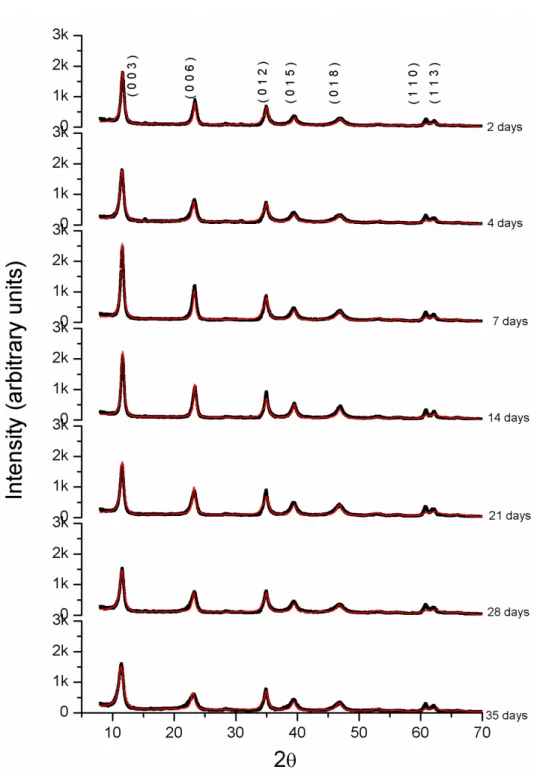
Figure 5.1 XRD for 20 Mg-Al Series. ... 55
Figure 5.2 XRD for 25 Mg-Al Series. ... 56
Figure 5.3 XRD for 30 Mg-Al Series. ... 57
Figure 5.4 XRD for 20, 25, and 30 Mg-Al Series. ... 58
Figure 5.5 Cell parameter c obtained for 20 Mg-Al and 25 Mg-Al Series. ... 61
Figure 5.6 3D Surface Color Map (a, b and c) and hypsometric (d) for D003. ... 62
Figure 5.7 3D Surface Color Map (a, b and c) and hypsometric (d) for D006. ... 63
Figure 5.8 3D Surface Color Map (a, b and c) and hypsometric (d) for Ds. ... 64
Figure 5.9 Diagram for hypothesis test sequence... 70
Figure 5.10 3D Surface Color Map (a, b, c, d, e) and hypsometric (f) for I=f(x,t). ... 77
Figure 5.11 Function fit: Rational only (a) fit with I = f ( x, t) (b, c, d). ... 79
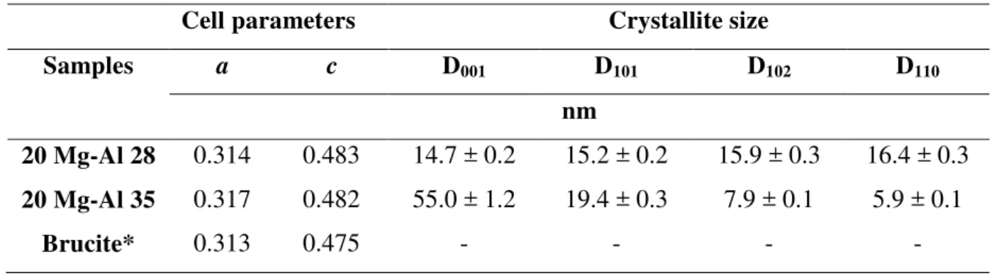
Figure 5.12 XRD samples with brucite: 20 Mg-Al 28 (a) and 20 Mg-Al 35 (b). ... 82
Figure 6.1 Thermo Gravimetric (a) and derivative (b) for the 20 Series. ... 84
Figure 6.2 Thermo Gravimetric (a) and derivative (b) for the 25 Series. ... 85
Figure 6.3 Thermo Gravimetric (a) and derivative (b) for the 30 Series. ... 86
Figure 6.4 Infra-Red for 20 Series samples. ... 90
Figure 6.5 Infra-Red for 25 Series samples. ... 91
Figure 6.6 Infra-Red for 30 Series samples. ... 92
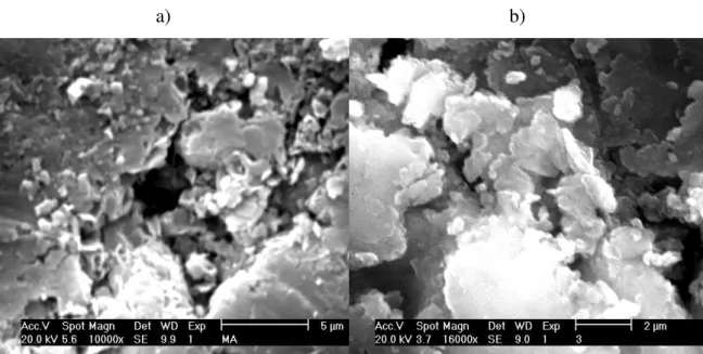
Figure 6.7 Micrographs: (a) 20Mg-Al 4 (b) 20Mg-Al 35 ... 94
Figure 6.8 Element maps for: a) 20 Mg-Al 4 and b) 20 Mg-Al 35 ... 94
Figure 6.9 Micrographs:a)25Mg-Al 4; b)25Mg-Al 14; c)25Mg-Al 21; d)25Mg-Al 28. ... 95
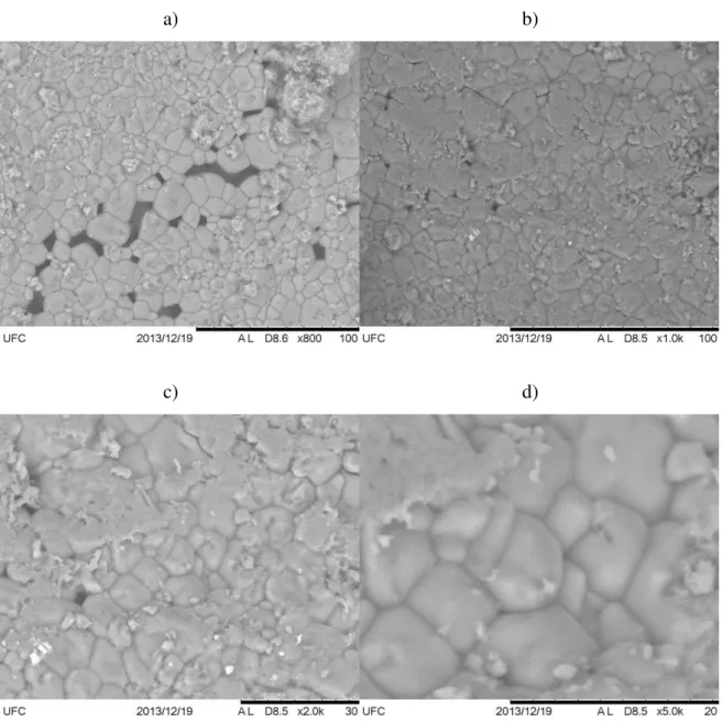
Figure 6.10 Micrographs for 25 Mg Al 4 sample without grinding. Magnification: a) 800 x; b) 1,000 x; c) 2,000 x; d) 5,000 x ... 96
Figure 6.11 Distribution of particle size in the not ground sample 25 Mg-Al 4. ... 98
Figure 6.12 Element maps for: a) 25 Mg-Al 4 and b) 25 Mg-Al 35 ... 98
Figure 6.13 Element maps for 25 Mg-Al 4 (without grinding) ... 99
Figure 6.14 Micrographs for 30 Mg-Al 4 sample. Magnification: a) of 50x; b) 80x. ... 100
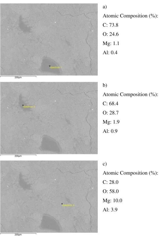
Figure 6.15 EDS for 30 Mg-Al 4 sample in different regions (a, b, c). ... 101
Figure 6.17 EDS for 30 Mg-Al 35 samples in different regions (a, b). ... 102
Figure 6.18 Element maps for: a) 30 Mg-Al 4 and b) 30 Mg-Al 35. ... 103
Figure 7.1. N2 adsorption-dessorption isotherm of 25Mg-Al 4 at 77 K. ... 104
TABLES LIST
Table 2.1 Chemical and physical adsorption... 37
Table 4.1 Dyes chemical structures and characteristics. ... 53
Table 5.1 Refinement parameters from 20 Mg-Al LDH Series. ... 60
Table 5.2 Refinement parameters from 25 Mg-Al LDH Series ... 60
Table 5.3 Mean (
x
) and Standard Deviation (s) for 003 and 006 peaks. ... 66Table 5.4 Applied statistics to βθ peaks shift at 00γ planes. ... 71
Table 5.5 Applied statistics to βθ peaks shift at 006 planes. ... 72
Table 5.6 Applied statistics to Crystallinity. ... 74
Table 5.7 Parameter c for the 30 Series... 75
Table 5.8 Parameters for the fit function. ... 78
Table 5.9 Cell parameters and crystallite size for the samples with brucite. ... 81
Table 6.1 Mass loss in the first stage. ... 87
Table 6.2 Mass loss in the second stage. ... 88
Table 7.1 Relative comparison among the experimental results. ... 105
Table 7.2 Fit for dyes adsorption in LDH samples. ... 107
ABBREVIATIONS
ANOVA Analysis Of Variance AB25 Acid Blue 25
BET Brunauer Emmett Teller
CI Color Index
EDS Energy Dispersive Spectroscopy FWHM Full Width at Half Maximum FCC Fluid Catalytic cracking
IUPAC International Union of Pure and Applied Chemistry ICDD International Center For Diffraction Data
ICSD Inorganic Crystal Structure Database LDH Layered Double Hydroxides
RB4 Reactive Blue 4
SEM Scanning Electron Micrograph TG Thermo Gravimetric
UV/VIS Ultra Violet Visible
UFC Universidade Federal do Ceará XRD X-Ray Diffraction
SYMBOLS LIST
qmax Maximum Adsorption Capacity kl Langmuir Equilibrium Constant kf Freundlich Equilibrium Constant
klf Langmuir-Freundlich Equilibrium Constant kt Toth Equilibrium Constant
q Adsorption Capacity Wave Length
θ Angle
Fhkl Structure Factor
Full Width At Half Maximum Intensity Dhkl Interplane Distance
x
Mean ValueMd Median Value
s Sample Standard Deviation CV Coefficient Of Variance
σ2 Population Variance µ Population Mean Value
s2 Sample Variance
Degree of Freedon
T Student Test
H0 Null Hypothesis H1 Alternative Hypothesis
a Cell Parameter
b Cell Parameter
c Cell Parameter
CONTENTS
INTRODUCTION ... 18
1. LAYERED DOUBLE HYDROXIDES ... 21
1.1 Structure ... 21
1.2 Hydrotalcite ... 23
1.3 LDH Applications ... 25
1.3.1 Industrial Applications ... 26
1.3.2 Environmental Applications ... 27
1.3.3 Medicine Applications ... 29
1.4 Synthesis Methods ... 30
1.5 LDH Textural Properties and Crystallinity ... 32
2 ADSORPTION AND DYES ... 36
2.1 Adsorption Processes ... 36
2.1.1 Chemical and Physical Adsorption ... 36
2.1.2 Adsorption Isotherm ... 37
2.1.3 Equilibrium Isotherms ... 38
2.2 Dyes... 40
2.2.1 Dyes Nomenclature ... 41
3 X-RAY DIFFRACTION ... 42
3.1 X-Ray Diffraction Theory ... 42
γ.1.1 Bragg’s Law ... 42
3.2 X-Ray Diffraction Techniques ... 43
3.3 Rietveld Method ... 46
3.3.1 The Peak Intensity ... 46
3.3.2 The Pseudo-Voight Function ... 47
3.4 Particle and Crystallite ... 48
4 MATERIAL AND METHODS ... 50
4.1 LDH Synthesis ... 50
4.2 LDH Characterization Analyses ... 50
4.3 Material and Procedures for LDH Adsorption ... 52
4.4 Software ... 53
5 X-RAY DIFFRACTION AND THE FIT FUNCTION ... 54
5.2 Hydrotalcite Cell Parameters ... 59
5.3 Hydrotalcite Crystallite Size ... 62
5.4 Statistical Approach to XRD Results ... 65
5.5 FIT Function ... 76
5.5.1 FIT Function possible applications ... 79
5.6 The non-Expected Brucite ... 81
6 THERMOGRAVIMETRY, INFRA-RED AND MICROGRAPHY ... 83
6.1 Thermo Gravimetric Analysis ... 83
6.2 Infra-Red Spectroscopy ... 89
6.3 Scanning Electronic Microscopy and Energy Dispersive Spectroscopy ... 93
6.3.1 Micrographs and EDS for the 20 Series ... 93
6.3.2 Micrographs and EDS for the 25 Series ... 95
6.3.3 Micrographs and EDS for the 30 Series ... 99
7 ADSORPTION APPLICATIONS ... 104
7.1 Adsorption-Desorption Isotherm ... 104
7.2 Dyes Adsorption ... 105
CONCLUSIONS ... 109
PROPOSALS FOR FUTERES RESEARCH ... 112
REFERENCES ... 113
APPENDIX ... 122
A. Scientific Production ... 122
18 INTRODUCTION
Chemical contamination of water from a variety of toxic derivatives, in particular heavy metals, pigments and aromatic, is a very serious problem presenting a high potential of human poisoning. Therefore there is a need to develop technologies that can remove pollutants from wastewater (SINGH et alli, 2009).
Fast commercial and industrial growth has resulted in more comfort for humans, but for many years man has not been concerned with the possible consequences of the environment. Consequently a very large amount of pollutants has been discharged creating serious impacts on soil and water (CHUANG et alli, 2008).
Textile dyes have been used for decades and are available in a great variety of colors. The process of dyeing consists of several steps which are chosen according to the nature of the textile fiber, structural features, and classification (GUARATINI and ZANONI, 2000). It is estimated that 40,000 tons of dyes are lost each year in wastewaters (MARSCH and REINOSO, 2006).
Most dyes are synthetic in origin and exhibit complex aromatic molecular structures that make them more stable and difficult to degrade (PONRAJ et alli, 2011). Textile industry dyes can be classified into three categories as follow: (a) anionic: direct, acid, reactive, (b) cationic: basic and (c) non-ionic: dispersed dyes (KYZAS et alli, 2013).
Traditionally, activated carbon has been used for adsorption of these dyes in complementary treatment. Studies indicate (PEREIRA et alli, 2003, AL-DEGS et alli, 2001) that activated carbon is more efficient in the removal of cationic dyes (such as methylene blue) than the anionic dyes (acid, direct and reactive dyes).
LOW and LEE (1997) have generalized that most biological sorbents (maize cob, bagasse pith, wood and peat) are more efficient in attracting cationic than anionic dyes. Studies with low cost inorganic materials such as clays and fuller's earth also indicate that inorganic materials have affinity for the cationic surfactants.
19 dyes by activated carbons (ABDELKADER et alli, 2011; ZHU et alli, 2005; BOUDIAF et alli, 2012).
Calcined and non-calcined LDH, in particular are a promising candidate for adsorption because of its relative ease of preparation, high capacity of anion exchange, reuse, high surface area and porosity (AUXILIO et alli, 2009; SAIAH et alli, 2009).
LDH belongs to a class of ceramic materials that present a structure formed by stacked layers of double metals hydroxides and an anion into the lamellar space. Their general formula, [M+21-x M+3x (OH)2]+x A-mx/m . nH2O, permits a large variety of combinations of different metals M+2 and M+3 (CREPALDI and VALIM, 1998; THEVENOT et alli, 1989; ALEJANDRE et alli, 1999; ARAÚJO, 2003; CHANG et alli, 2005; TRONTO, 2006).
The purposes of this research were to synthesize and study hydrotalcite in depth to verify how its textural properties are affected by molar ratio and aging time; to attempt to predict its crystallinity and crystallite size before synthesis (surface fit); and to evaluate its performance as a dye adsorbent.
This kind of investigation, although important to ensure a more thorough understanding of hydrotalcite, has not been reported in the literature.
In order to achieve these objectives it was necessary to characterize the materials in such a way as to enable a quantification of the textural properties. The main analysis employed was the X-ray diffraction, which allows determination and quantification of phases, calculation of cell parameters, crystallinity and crystallite size. Quantitative analyses were also important to confirm the result from X-ray diffraction and to get more information about the properties of the LDH studied.
Textural properties like crystallinity, crystallite size, particle size distribution, surface area and porosity are important to LDH applications. Some authors studied these characteristics and manifest interest in proposing a synthesis path that could impart specific properties to the LDH obtained (OH et alli, 2002; BRAVO-SUAREZ et alli, 2004; SHARMA et alli, 2007; SAIAH et alli, 2009; BENITO at alli, 2010; BERBER et alli, 2013). However, none of them has yet proposed the kind synthesis path pursued in neither this study nor a type of function to predict these characteristics as it was proposed in this research.
21 1. LAYERED DOUBLE HYDROXIDES
1.1 Structure
Layered Double Hydroxide (LDH) belongs to a class of ceramic materials that present structure formed by stacked layers of double metals hydroxides and an anion into the lamellar space. Differently from common clays LDH presents positive charge on their surface and lamellar structure with a general formula (THEVENOT et alli, 1989; CREPALDI and VALIM, 1998; ALEJANDRE et alli, 1999; ARAÚJO, 2003; CHANG et alli, 2005; TRONTO, 2006):
[M+21-x M+3x (OH)2]+x A-mx/m . n H2O
where,
M+2 is a divalent metal cation (eg: Mg+2, Mn+2, Zn+2, Ni+2, Fe+2, Cu+2, Ca+2, etc.); M+3 is a trivalent metal cation (eg: Al+3, Cr+3, Co+3, Ni+3, Fe+3, etc.);
A-m is an interllamelar anion containing water molecules around it (CO3-2, NO3-, Cl-, F-, Br-, I-, SO4-2, CrO4-2, [Fe(CN)6]-4, [NiCl4]-2 , etc.);
x = M+3/ (M+2 + M+3) is the molar metal ratio.
LDH general formula shows that is possible a large variety of combinations of metals and interllamelar anions and consequently can be obtained many different kind of this cationic clay. Some authors say that the molar ratio varies from 0.20 to 0.33 to obtain pure LDH (SAIAH et alli, 2009; CAVANI et alli, 1991). KUSTROWSKI et alli (2005) suggest a range of 0.17 to 0.50 for some LDH. If it is combined just the examples of metals and anions listed above and vary the molar ratio from 0.20 to 0.33 in a tenth we obtain 4,900 different LDH.
22 LDH layers can be seen as having structures similar to that of brucite with the formula [Mg (OH)2]. Figure 1.1 shows brucite structure, where the Mg+2 ions have octahedral coordination with hydroxyl groups by edges that extend in infinite layers (GOLDANI, 2007).
1Figure 1.1 Brucite structure, Mg (OH)2.
Source: GOLDANI, 2007.
The divalent ions in LDH can be isomorphically replaced by trivalent ones, generating a residual positive charge that is compensated by anions located in the interlayer space (RIBEIRO, 2008; SAIAH et alli, 2009). Figure 1.2 shows the outline of a generic LDH structure with layers composed by a double hydroxide metals M+3 and M+2 and hydrated interlamellar anions.
2Figure 1.2 LDH general structures.
23 1.2 Hydrotalcite
Hydrotalcite is a type of LDH with Mg and Al atoms in the lamellae structure and present the following general formula (FERREIRA, 2001; CHANG et alli, 2005; RODRIGUES, 2007; SILVA, 2008; PÉREZ et alli, 2009):
[Mg1-xAlx(OH)2]x+[(CO32-)x/2nH2O]
The metal ratio x = Al+3/(Mg+2 + Al+3) may vary, theoretically, in a large range, although, for some authors (FERREIRA, 2001; CHANG et alli, 2005; RODRIGUES, 2007; PÉREZ et alli, 2009) a range is limited from 0.2 to 0.33 to obtain a LDH as a unique phase. According to SILVA (2008) and ALEJANDRE et alli (1999), the metal ratio, x, may vary from 0.17 to 0.33.
Probably values above 0.33 to hydrotalcite is not possible because the elevated number of neighbor aluminum atoms could promote formation of amorphous
bohemite (-AlO(OH)) and/or gibsite (Al(OH)3) that would not be detectable in X-rays Diffraction (CAVANI et alli, 1991; NODA PEREZ et alli, 2004). On the other hand low values of x could promote a high density of magnesium in the octahedral sheet and probably a brucite phase would be formed (CAVANI et alli, 1991)
The metal ratio is an important parameter in this formula because it determines the charge density surface (AUXILIO et alli, 2009) and consequently the properties in adsorption applications (AGUIAR et alli, 2013). Furthermore adsorption, there are other industrial applications to hydrotalcite, like fluid catalytic cracking (POLATO et alli, 2009), hydrogenous oxidative catalyzer (MEIRA and CORTEZ, 2007), biomaterials (NAIME FILHO et alli, 2008), etc.
Hydrotalcite is described as a compound of brucite-like structure, where the ions Mg+2 and Al+3 are combined in octahedral sites of hydroxides sheets (CARJA et alli, 2001) and can be a natural or synthetic material (KUSTROWSKI et alli, 2005).
24 FRONDEL (1941) described hydrotalcite as a foliated and contorted platy and fibrous mineral. Figure 1.3 shows the hydrotalcite mineral from a mine at Urals, Russia.
3Figure 1.3 Hydrotalcite mineral from a mine in Middle Urals, Russia.
Source: http://www.mindat.org/photo-68315.html (access in October, 20th, 2013).
Such a clay presents a molar metal proportion of 3:1 of Mg and Al and the formula, [Mg6Al2(OH)16]CO3.4H2O. It consists of layers of magnesium and aluminum hydroxides intercalated with hydrated carbonate ions (CO3-2) (ALEJANDRE, 1999; REIS, 2009).
Hydrotalcite shows a stack layer sequence that classifies it as rhombohedral
crystal system with c parameter equal to three times the basal space belonging to R3m space group (CREPALDI and VALIM, 1997) and cell parameters a = b = 3.054(3) nm
25
4Figure 1.4 hydrotalcite rhombohedral structure.
Source: CREPALDI and VALIM, 1997 (with adaptations).
Hydrotalcite is the most known and studied LDH and it is taken as a reference for many isomorphous compounds even with different metals than Mg and Al. LDH with the similar structure is known as hydrotalcite-like compounds (KOVANDA et alli, 2005) and present many industrial and medicinal applications that is covered in the next section.
1.3 LDH Applications
LDH has been studied extensively in recent decades because they present several applications, properties and versatility. Figure 1.5 shows a histogram with the number of papers per year since 1980 to 2009. It shows the development of the number of researches performed on LDH clay type.
A search for “Layered Double Hydroxides” at www.periodicos.capes.gov.br
26
5Figure 1.5 Growth of LDH researches.
Source: REIS (2009).
1.3.1 Industrial Applications
LDH clays, mainly hydrotalcite, used in this research, shows high surface area, therefore are used as adsorbents of industrial contaminants as dyes (CONCEIÇÃO et alli, 2007 SAIAH et alli, 2009; AGUIAR, et alli, 2013). AUXILIO et alli (2009) used calcined hydrotalcite to uptake acid blue 9 and obtained the best result in a 5.6 molar ratio.
SANTOS (2007) studied hydrotalcite with a molar proportion 3:1 (Mg:Al) modified as heterogeneous catalyst for biodiesel production. Modification of Hydrotalcite occurred with the addition of some elements (zinc, tin, barium, cerium and calcium) and subsequent calcination. The survey revealed great potential for use of hydrotalcite conversion of soybean oil to methyl esters according to the European standard for biodiesel.
27 Hydrotalcite was also used as substrates for catalysts for oxidative dehydrogenation of light paraffins. The mixed oxide catalysts of vanadium and molybdenum were prepared and evaluated in different proportions in the decomposition reaction of isopropanol (MEIRA and CORTEZ, 2007).
Calcined hydrotalcite was used in the catalytic conversion of ethanol in the fixed bed reactor by VILLANUEVA (2000 and 2005). LDH calcination significantly increased surface area of the product formed, magnesium and aluminum double oxides. The author set a variation in the composition of the metal ions magnesium and aluminum as the same way as AUXILIO et alli (2009) did, but with different applications. The results just showed, for both cases, that the calcination can increase LDH surface and consequently improve their adsorption characteristics.
KAGUNYA and JONES (1995) used various types of calcined LDH as catalyst from aldol condensation of acetaldehyde. The authors observed that the large surface area of LDH favors the activity of self-condensation of acetaldehyde.
This sub-section shows that some parameters are important in LDH industrial applications: calcination, molar metal ratio and the nature of metal ion.
1.3.2 Environmental Applications
Contamination of water and soil from a variety of toxic derivatives, in particular heavy metals, pigments and aromatics, is a very serious problem presenting a potential of human poisoning. So there is a need to develop technologies that can remove pollutants from wastewater (SINGH et alli, 2009). There are many researches with applications of LDH uptake of many chemicals released into waters and soils, including industrial dyes that have a great concern for many researchers.
28 CONCEIÇÃO et alli (2007) synthesized hydrotalcite with a composite iron hydroxide. They used the pure clay and composite for removal of reactive red dye and chromate under varying pH conditions. The aim was to compare the adsorption isotherms of pure clay and composite clay for a possible magnetic field separation process.
GOLDANI (2007) developed a methodology for extract metallic elements manganese and iron effluents from coal mining. In this study, adsorption isotherms were compared to three types of clays: natural bentonite, montmorillonite and synthetic hydrotalcite. The author has found a significant difference in the adsorption from hydrotalcite compared to bentonite and montmorillonite, especially for manganese adsorption. Hydrotalcite showed a 90% greater efficiency than the others two clays.
The adsorption of industrial contaminants by LDH shows wide application, but it is necessary to analyze how many cycles LDH can be used in a process of adsorption-desorption. ZAMBONI et alli (2005) studied calcined hydrotalcite in relation to the cycles of adsorption of anionic contaminants from textile industries.
Figure 1.6 shows that the adsorption capacity varies slowly with the number of adsorption-calcination cycles. The reduction in uptake was 99.9%, 99.7% and 99.2% from the first cycle to the 2th, 3th, and 4th cycles, respectively, showing that LDH can be regenerate to be used in many cycles.
6Figure 1.6 Cycles of adsorption and desorption.
29 MIOTTO et alli (2008) have studied and compared the adsorption of methylene blue and direct blue textile dyes with and without added surfactant SDS (sodium dodecyl sulfate) on hydrotalcite. They found that with the addition of SDS to hydrotalcite, methylene blue adsorption varies from 26% to 98%. On the other hand SDS did not affect the adsorption of direct blue that increased from 97.6% to 97.7%. Thus the nature of the dyes is important in LDH adsorption.
In this research methylene blue was also studied on hydrotalcite adsorption and compared with acid blue 25 and reactive blue 4 in just one cycle. Studies of a larger number of cycles must be performed to verify the economic feasibility of using hydrotalcite and other LDH as adsorption of contaminants from industrial wastewater.
The following parameters are important in environment applications: temperature, ionic concentration, pH conditions, and nature of contaminant adsorbed.
1.3.3 Medicine Applications
Many researches are focused on health using LDH, mainly hydrotalcite that among different applications is also used as a drug to combat reflux and as antacid. Hydrotalcite is patented as antacid by the name Talcid ® from Bayer.
CUNHA et alli (2009) conducted a quite interesting study showing the varied applications of LDH as biomaterials. The article approaches LDH applications for storage and release of species of biological and therapeutic interest. It shows a list of 44 intercalated drugs on hydrotalcite and Zn-Al-LDH.
LDH have specific characteristics that allow its use as carrier of drugs: biocompatibility, low toxicity and high integration of ionic species. With these features it is possible to promote the sustained release of inserted species. The cholic acid is the main acid produced by the bile and acts as aiding in the digestion of fats. SILVA and VALIM (2007) studied the intercalation of this acid in hydrotalcite to release it in the body of patients with deficiency of this substance.
30 RIBEIRO, 2008; REIS, 2009). The study concluded that it is possible to use the system described, however it is necessary to coat LDH to prevent acid attack from gastrointestinal tract.
Conjugated porphyrins are macrocyclic compounds possessing four pyrrole rings. They are present in some proteins and are essential for biological activities in the transport and storage of oxygen promoted by hemoglobin. HALMA (2004) studied different ways of ironporphyrins immobilization in LDH in order to check the catalytic activity.
A study comparing calcined and non-calcined hydrotalcite in adsorption of cholate anion (produced by the bile) under different conditions of pH and temperature were made by NAIME FILHO et alli (2008). This study found that the calcined hydrotalcite presents considerably more adsorption of cholate anion than the non-calcined one.
This section shows that LDH can be used as drug storage and a delivery agent, antacid and an adsorbent for substances in excess in a human body. As the same way as the industrial application (KAGUNYA and JONES, 1995; VILLANUEVA, 2000 and 2005; AUXILIO et alli, 2009) the calcination of LDH can improve their surface area and increase the adsorption capacity. Furthermore calcination, temperature and pH are important in medicinal applications.
1.4 Synthesis Methods
There are different methods of LDH synthesis that are mentioned by several authors. Among various methods are highlighted the most common (SANTOS, 2007; RODRIGUES, 2007; CREPALDI and VALIM, 1998; REIS, 2009; FERREIRA, 2001; HE et alli, 2005):
1. Co-precipitation at constant pH
2. Co-precipitation at variable pH or salt-based method 3. Salt-oxide method
31 Co-precipitation at constant pH: in this method the solutions of cation salts are simultaneously added to the anion to be intercalated. It is necessary to use a potentiometer to be able to control pH. This method has the advantage of achieving greater homogeneity of the product synthesized (CREPALDI and VALIM, 1998; NODA PEREZ et alli, 2004; KUSTROWSKI et alli, 2005; SANTOS, 2007).
Co-precipitation at variable pH: consists in addition of a solution containing salts of the divalent and trivalent cations mixed to a solutionof the anion to be intercalated. The parameters such as initial concentration of salt and anion to be intercalated, agitation, temperature must be controlled in order to avoid the formation of undesirable phases, as simple hydroxides (NODA PEREZ et alli, 2004; HE et alli, 2005; KOVANDA et alli, 2005; RODRIGUES, 2007; SHARMA et alli, 2007; KOVANDA et alli, 2009;).
Salt-oxide method: this method basically consists of a reaction between oxides of divalent and trivalent metal salt cations. In this type of reaction the addition of reactants is controlled in order to obtain a constant pH (FERREIRA, 2001; HE et alli, 2005).
Hydrothermal synthesis: it is a kind of synthesis which occurs at higher temperatures. It uses two oxides of di and trivalent metals to form a suspension that is added in an acid with the ion wanted in the interlamellar space (RODRIGUES, 2007). It is important to differentiate it from hydrothermal treatment that occurs after synthesis.
Intercalation method is a method of obtaining new LDH from an existing precursor. It is used a concentrated anion solution to be intercalated. It is also very common to use precursors containing carbonate that can be protonated at high pH and thus avoids the destruction of the lamellae hydroxides (CREPALDI and VALIM, 1998; HE et alli, 2005).
In addition to the methods listed before there are other methods to synthesize LDH: sol-gel synthesis and electrochemical synthesis(RODRIGUES, 2007), urea hydrolysis (BENITO et alli, 2008; MEIS, 2010), synthesis using microwave (HERRERO et alli, 2007), and reconstruction method (LI et alli, 2010; CHANGa et alli, 2011).
32 1.5 LDH Textural Properties and Crystallinity
The methods listed in the previous section for all LDH syntheses are shown relatively simple. However, many factors can influence the outcome textural characteristics of the products. Thus it is necessary to control these parameters to obtain the wanted LDH with crystallinity and purity (CREPALDI and VALIM, 1998).
Several factors must be taken into account for LDH synthesis, for example: the degree of substitution of cations M+2 for M+3, the nature of the cations, the nature of the interlayer anion, pH synthesis, and in some cases, the synthesis atmosphere. Furthermore, to obtain more crystalline material the following parameters must be controlled: concentrations of the salt solutions, the rate of addition of solution, the degree of agitation (RODRIGUES, 2007; REIS, 2009).
FARIAS et alli (2009) have discovered that the synthesis method influence on the obtained LDH crystallinity. Figure 1.7 shows a comparison of some LDH syntheses. The urea hydrolysis and the synthesis at variable pH accompanied by hydrothermal treatment seem to be better than the others syntheses.
SAIAHet alli (2009) carried out a study of the hydrothermal effect on Ni-FeCO3 LDH treatment under various conditions of temperature and aging. They concluded that there was an increase in crystallinity as the temperature and aging were raised and accompanied by a reduction in LDH surface area. It was also noticed that there was an increase in the amount of amorphous material when the temperature of the hydrothermal treatment approach 200 °C.
33
7Figure 1.7 Synthesis Influence in LDH crystallinity.
Source: FARIAS et alli, 2009.
The terms crystallinity and degree of crystallinity are used in this text as a textural property of clays (OH et alli, 2002; BRAVO-SUAREZ et alli, 2004; SHARMA et alli, 2007; SAIAH et alli, 2009; BENITO et alli, 2010; CHANGb et alli, 2011; BERBER et alli, 2013) however, there are no definition accepted by the scientific community in this field. There are some equation and definitions for polymers crystallinity and procedures to obtain the crystallinity for some clay minerals like kaolinite, illite, smectite, etc.
Crystallinity for polymers is defined by IUPAC (ALLERA et alli, 1989) as the presence of three-dimensional order on the level of atomic dimensions; the term
“degree of crystallinity” is also defined as the fractional amount of crystalline phase in the polymer sample relatively to the total of polymer crystalline and amorphous phase. It may be calculated for mass fraction (Wc) or volume fraction (φc).
There are some methods recommended to calculate the degree of crystallinity in polymers: by calorimetry, density measurements, infra-red spectroscopy and by X-Ray diffraction. The equation to calculate the degree of crystallinity by X-Ray diffraction is given as follows (ALLERA et alli, 1989):
34 where Ic and Ia are the integrated intensities scattered over a suitable angular interval by the crystalline and amorphous phase. Kx is a calibration constant (ALLERA et alli, 1989). A similar and simpler equation is proposed by KAVESH and SCHULTZ (1969):
Wc = Ic/(Ic + Ia) 1.2
where Ic and Ia are the area under certain selected crystalline peaks and peaks considered amorphous, respectively.
In general, X-ray diffraction can provide information about the atomic arrangement in materials with high organization, low organization and materials that may also present part of its constitution crystalline and amorphous (HE, 2009). Thus a measure of Full Width at Half Maximum (FWHM) of the peaks could be related with crystallinity. It was done for some authors like AMIGÓ et alli (1994) and CONSTANTINO et alli (1998).
Clays like kaolinite present some definition and methods to measure its crystallinity. APARICIO and GALÁN (1999) have summarized some methods for the XRD determination of kaolinite crystallinity indices: Hincley, Stoch, Range & Weiss, Lietard, Hughes & Brown, Plançon & Zacharie and Indices of Amigó. They compared statistically the methods to found the better one to measure crystallinity indices of eight different kaolinites. All of them utilize relations of areas and height of peaks from the patterns, except for the Indice of Amigó that uses a relation of FWHM between 001 and 002 peaks (AMIGÓ et alli, 1994).
Crystallinity degrees were indicated in a qualitative way: very low, low, good and very good by CONSTANTINO et alli (1998). They synthesized hydrotalcites-like compounds and analyzed properties of crystallinity degree of the samples by evaluation of the X-ray diffraction pattern based on the number of reflections, their intensity and their FWHM.
KÜHNEL et alli (1975) studied crystallinity of goethite samples associated with silicates. They quantified the crystallinity of these minerals on the basis of statistical measures from the analysis of their X-ray line profiles.
35 time and reaction temperature. It was evaluated how the particles size varied with the conditions of synthesis.
Hydrotalcites like compounds with nickel and aluminum were synthesized by KANNAN et alli (1996) with molar ratio varying from 0.20 to 0.33. They compared the intensity of the 006 peaks in their XRD pattern and associated them with their degree of crystallinity. Furthermore they performed hydrothermal treatments on aged samples to study the change in textural properties. They verified an increase in the intensity and sharpness of the peaks in XRD and concluded that the crystallinity was enhanced.
SHARMA et alli (2007) had done a summation of 003 and 006 peaks intensity to measure crystallinity in hydrotalcite with different molar ratio. In previous work (LIMA et alli, 2012) a study with Mg-Al LDH adsorption was carried out with adsorption of reactive blue 4 and acid blue 25 in different aging times: 4, 14 and 28 days. Crystallinity was measured by the intensity of the 003 peaks of the XRD patterns. The XRD diffraction showed a reduction in crystallinity with aging time as the same way a reduction in adsorption took place.
Maybe crystallinity could be better measured by FWHM of their peaks, this parameter is directly associated with particles size through the Scherrer equation (3.11). However one of the samples series could not be refined to obtain the correspondent particle size. Thus in this research crystallinity was adopted as a measure of the intensity of the 003 peaks of the XRD patterns the same way as LIMA and co-workers (2012) did.
36 2 ADSORPTION AND DYES
This chapter describes the fundamental of adsorption process, adsorption isotherms and the classification of dyes that were used in this research.
2.1 Adsorption Processes
Adsorption is a process of mass transfer and occurs between a fluid and a solid adsorbent which retain molecules of liquids or gases on its surface. The solid that adsorbs is known as adsorbent while the fluid is adsorbate (MARSH and REINOSO, 2006).
The adsorbents are natural or synthetic substances with microcrystalline structure whose pore inner surface is accessible to a selective combination between the solid and solute. The adsorbents used in more large scale are activated carbon, silica gel, activated alumina and various types of clays (PERRY and GREEN, 2008).
The process is related to the interaction energy of adsorbent and adsorbate and is classified in chemical and physical adsorption depending upon some criteria, showed in Table 2.1, like heat of adsorption, mono or multilayer formation, etc.
2.1.1 Chemical and Physical Adsorption
The adsorption process can present different characteristics with respect to the energy between the adsorbent and the fluid molecules adsorbed. Depending on the magnitude of this energy the process is classified as physical adsorption or chemical adsorption. Table 2.1 shows the major differences: heat of adsorption, specificity, number of adsorption layer, electron transfer and temperature range (RUTHVEN, 1984).
37
1Table 2.1 Chemical and physical adsorption.
Physical Adsorption Chemical Adsorption
Low heat of adsorption
(< 2 to 3 times the latent heat of evaporation)
High heat of adsorption
(> 2 or 3 times the latent heat of evaporation)
Not specific Highly specific
Monolayer or multilayer Only monolayer
Without dissociation Dissociation can occur
No electron transfer Electron transfer
Significant at low temperatures
Wide temperature range
Source: RUTHVEN, 1984.
2.1.2 Adsorption Isotherm
Adsorption is a mass transfer process and it is necessary to know how far it reaches. Such information can be obtained from the adsorption isotherms. In physical adsorption the isotherm is a graph between the amount adsorbed (mmol.g-1) against the relative pressure (p/p0) of the adsorbate (MARSH and REINOSO, 2006).
The most common physisorption isotherms are described by one of the six types showed in Figure 2.1. All of them obey to Henry’s law in region of low pressure, i.e., the amount of gas adsorbed is proportional to pressure (SINGH et alli, 1985).
Figure 2.1 shows the IUPAC (International Union of Pure and Applied Chemistry) classification of physical adsorption isotherms. In the case of isotherm I adsorption represents only one layer that can occur in micro porous materials, the amount adsorbed approaches a limiting value as (p/p0) tends to unity. The model II shows the adsorption in a non-porous material. In the beginning is formed a monolayer and as the relative pressure increases the multilayer adsorbed predominates.
38 Type V shows low energy in adsorption and it is related to the type III where the adsorbent-adsorbate interaction is weak and the hysteresis shows the presence of mesopores. The type VI isotherm represents a stepwise multilayer on a uniform non-porous surface (GUELFI, 2007; MARSH and REINOSO, 2006; SINGH et alli, 1985).
8Figure 2.1 IUPAC adsorption isotherm classifications.
Source: SINGH et alli, 1985.
2.1.3 Equilibrium Isotherms
There are many mathematical models to describe adsorption isotherm, among them, the following are highlighted: Langmuir, Freundlich, Langmuir-Freundlich e Toth.
39 Langmuir model is written as follows (KYZAS and LAZARIDIS, 2009; RUTHVEN, 1984): eq L eq L
C
k
C
k
q
q
1
max 2.1 whereqmax (mg/g) is the maximum adsorption capacity, kL (mL/mg) is the Langmuir equilibrium constant.
Freundlich isotherm model encompasses the heterogeneity and the exponential distribution of active sites and their energies. The isotherm provides no saturation of the adsorbent surface, it is expected an endless coverage. Freundlich model is described as follows (KYZAS and LAZARIDIS, 2009):
n eq F
c
k
q
1/ 2.2where kF (mg1-1/nL1/n/g) is the Freundlich constant associated to adsorption capacity and 1/n is the heterogeneity factor.
The third model combines the previous two models and is known as the Langmuir-Freundlich isotherm model that describes heterogeneous surface. Essentially the Langmuir-Freundlich isotherm is a Freundlich isotherm with an asymptotic property that approaches the maximum at high concentrations.
Furthermore, Langmuir-Freundlich isotherm tends to Langmuir when the parameter of heterogeneity "b" tends to unity. The mathematical expression for the Langmuir-Freundlich model is described by equation 2.3 (KYZAS and LAZARIDIS, 2009):
b eq LF b eq LFc
k
c
k
q
q
1
max 2.340 Toth isotherm model is an enhancement of Langmuir and Freundlich isotherms. It originated from the potential theory and is applied in heterogeneous adsorption where it assumes a nearly Gaussian energy distribution. Toth model is described as follows (ALLEN et alli, 2004; MOUZDAHIR et alli, 2010):
mT
mTeq T eq T c k c k q
q max 1/
1
2.4
where kT is the Toth constant and mT is the heterogeneity factor.
Similarly to the model of Langmuir-Freundlich, Toth model tends to Langmuir model when constant mT tends to unity.
2.2 Dyes
Dyes are classified according to chemical structure (used for the organic chemist) or by its application method that depends upon the kind of substrate it is applied (IQBAL, 2008). Textile industries dyes can be classified into three categories as follow: (a) anionic: direct, acid, reactive, (b) cationic: basic, and (c) non-ionic: dispersed dyes (KYZAS et alli, 2013). The applied method definition for dyes is described according to HUNGER (2003):
Direct dyes are used mainly in materials from cellulose, for example: cotton, viscose or paper. They can be used on cellulosic fiber “directly” without any
previous treatment like metal salts that are used with others categories of dyes. Their water solubility is less than the acid dyes.
Acid dyes are water-solubilizing and easily to dissociate in a wide acidity range. Used in acidic dye baths in nylon, paper, leather, silk, etc.
Reactive dyes are compounds that contain groups capable to form covalent bonds with substrate. It is used in cotton, wool, silk, and nylon. The reaction to bind covalently to the fiber occurs under influence of heat and alkaline pH.
41 Disperse dyes are colorants that present a disperse colloidal form and a low water solubility or water-insoluble in some of them. They are used in hydrophobic fibers and synthetic one, like polyester, cellulose acetate, polyamide, and acrylic. It is often applied at high temperatures and or pressure.
2.2.1 Dyes Nomenclature
Dyes can be named by the Color Index (C.I.) or by their commercial trade name. The commercial names are usually composed of three parts: the first is a trademark that designates the manufacturer and the dye’s class; the second is the color; and the third one is a number and or letters used as a code that indicate the properties of the dye. These codes are not standardized and so their properties associated with their number (HUNGER, 2003).
For example: acid blue 25, reactive blue 4 were used in this research, can be abbreviating to AB25 and RB4. The C.I. name for a dye derives from the application class that the dye belongs, its color and hue. It is represented by five numbers in this index. For example, AB25 has its Color Index, C.I. 62055.; RB4, C.I. 61205.
42 3 X-RAY DIFFRACTION
This chapter aims to describe to the reader, in a superficial way, the principles of the most important analysis for materials science, X-Ray Diffraction (XRD) and the theory for determination of crystallite size using the well-known Scherrer equation.
3.1 X-Ray Diffraction Theory
X-ray diffraction is one of the most important and most widespread techniques for materials characterization and gives information on atomic scale structure of crystalline compounds (WASEDA et alli, 2011).
The X-ray diffraction is the phenomenon of interaction between an incident X-ray beam and the electrons of the atoms of a material, related to coherent scattering. The term coherent is associated with Thompson scattering of diffracted beam which present the same wavelength as the incident beam (WOOLFSON, 1997).
3.1.1 Bragg’s Law
In a material where the atoms are arranged periodically in space, characteristic of crystalline structures, the phenomenon of diffraction X-ray scattering occurs in directions that obey Bragg's law, Equation 3.1 (CULLITY, 1956).
Assuming a monochromatic beam of a specific wavelength ( ) relates to a crystal at an angle θ, called the Bragg angle, equation 3.1 is the Bragg’s law:
n = β |dhkl|senθ 3.1
where θ corresponds to the angle measured between the incident beam and a crystal plane, "dhkl" is the distance between the planes of atoms and "n" the diffraction order, an integer.
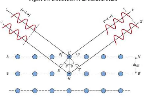
43 dhkl is the distance between two consecutive planes, so the difference in the path 1-1’ and the path β-β’ will be the distance SQT equivalent to 2|dhkl|senθ. It is necessary that this distance, 2|dhkl|senθ, be an integer multiple of the wavelength to satisfy a constructive interference (WASEDA et alli, 2011).
9Figure 3.1 Diffraction of an incident beam
Source: CALLISTER JR. and RETHWISCH, 2012.
3.2 X-Ray Diffraction Techniques
Diffractometer is the traditional instrument used to discover the internal structure of a crystalline substance. For samples powder analysis basically consists in measuring the intensity of the diffracted X-rays from the sample as a function of diffraction angle for a known wavelength X-ray (WASEDA et alli, 2011).
Figure 3.2 shows a flow chart of a diffractometer. A monochromatic beam of X-rays emitted by the source F while the sample powder is placed on the point S that rotates together with the detector in C that counts the number of photons. As they move the counter in a constant angular velocity, it is recorded the number of counts of the diffracted beam as a function of βθ (JENKINS and SNYDER, 1996).
44
10Figure 3.2 Scheme operation of the X-ray diffractometer
Source: JENKINS and SNYDER, 1996.
A divergent X-ray beam from F passes through a divergence slit (DS), then
through a collimator, Soller Slit (SS1), before it gets the specimen (S) at an angle θ. The X-rays are diffracted at an angle βθ and pass through a second parallel collimator (SSβ),
through the receiving slit (RS), to the detector slit (AS) (JENKINS and SNYDER, 1996).
The diffracted beam is usually expressed through peaks that stand out, recorded a spectrum of intensity versus angle βθ, constituting diffraction pattern. The intensities obtained at angles βθ represented by the diffraction peaks correspond to diffraction of the incident beam of a particular set of crystal planes, which have the same interplanar distance, each with Miller indices hkl (WASEDA et alli, 2011).
The information obtained from each peak is the intensity and the angular position (βθ) and consequently the substance pattern. Each crystalline compound shows a characteristic diffratometric pattern, allowing their identification through the angular positions and relative intensities of the diffracted peaks (LENG, 2008).
X-ray diffraction can provide information about the atomic arrangement in different levels of organizations, high, medium and low and may also present part of its constitution crystalline and amorphous (HE, 2009).
45 the samples with this technique is necessary to evaluate some structural information as the structure factor.
It is wave function of the beam reflected by the hkl plane of a unit cell (PAIVA-SANTOS, 2001). The equation is defined by HAMMOND (2009):
N n n n n nhkl f i hx ky lz
F
0
) (
2
exp 3.2
where fn is the atomic scattering factor and 2i(hxnkynlzn) is the phase φn of the nth atom in the motif with fractional coordinates (xn yn zn). The scattering factor can be calculated by the following equation (PAIVA-SANTOS, 2001):
2
0exp( )
Bsen f
fn n 3.3
where fn0the scattering factor for the rest atom and B is the thermal parameter.
This structure factor is used to evaluate the relationship between the structures of crystals and the intensity of the diffracted X-rays of each crystallographic plane measured. In addition to the structure factor, it is also important to consider the polarization, multiplicity, Lorentz, absorption and temperature factor (WASEDA et alli, 2011).
The identification of a crystalline compound is obtained by comparing the XRD patterns with individual phase’s pattern based on the set of d spaces in terms of θ or βθ and their relative intensities (RIBEIRO, 2010).
There are several programs that permit a collection of diffraction patterns allowing the application of diffraction refinement of the crystal structures and quantification of polyphase compounds.
The patterns are available in specialist databases sites as the International Center for Diffraction Data (ICDD) or Inorganic Crystal Structure Database (ICSD).
46 3.3 Rietveld Method
It is a crystalline structural refinement used with X-ray or neutron diffraction and it is based on the better approximation of the calculated and the observed diffractogram. The diffraction pattern is obtained from a constant βθ increment in a scan
process (PAIVA-SANTOS, 2001).
Instrumental and structural parameters are used in the Rietveld method to calculate a phase pattern of diffraction. The structural parameters are: atomic coordinates (x,y,z) in unit cell, thermal vibration, occupational density, cell parameters (a,b,c) and the angles with crystallographic axis (α, , ). The instrumental parameters are: reflections profile, global parameters, intensity parameters and the crystallite preferential orientation parameter (YOUNG et alli, 1993).
3.3.1 The Peak Intensity
The refinement is based on the least squares method that minimizes the square difference between the observed and calculated intensity for all the peaks in the analyzed pattern. The following equation shows how it is calculated (PAIVA-SANTOS, 2001). 2 ) ( calc i i obs i i I I
w
M
3.4where obs i
I and calc i
I are the intensities of the observed and calculated for the ith point
and wiis the weight, obs i
i I
w 1/ .
47
i obs i i e I w p n R 3.6where n is the number of observed points and p is the number of adjusted parameters. The ratio Rwp/Re is known as the goodness of fit or “χ factor” and is a
measure of how well the fitted model accounts for the data (YOUNG et alli, 1993).
e wp R R
S 3.7
Values of the quality of the fit (S) about 1.0 mean a good adjust of the data.
3.3.2 The Pseudo-Voight Function
The Rietveld method is based in a function to adjust the shape of the peak. The intensity of the diffraction peak is distributed by a profile function. There are many functions that depend on the characteristics of the equipment and the kind of radiation used. In this work was used a pseudo-Voight(p-V) function. It is a linear combination of a Lorentzian (L) and a Gaussian (G) defined by the following equation (PAIVA-SANTOS, 2001): ) ( ) 1 ( )
(x G x
L V
p
3.8The parameter defines the contribution of each function and is calculated by the
following equation:
B
A N
N
2 3.9A
N and NB are refineable parameters.
48 W
V U
Hk tan2 tan 3.10
Where U, V and W are the refinement parameters from the standard crystal (LaB6) used in this research.
3.4 Particle and Crystallite
The term particle size is used in physics as the same meaning of grain size in engineering and refers to a set of many fine units of single crystals known as crystallites (WASEDA et alli, 2011). Figure 3.3 shows the differences from particle size and crystallite size. It is noteworthy to mentioning the term particle used in engineering as a discrete and solid unit that can present a single or multiphase (REED, 1988) and according to RAHAMAN (2003), it can be a single crystal, polycrystalline or a glass.
11Figure 3.3 Diagram for particle and crystallite size
Source: adapted from WASEDA and co-workers, 2011
The width of a diffraction peak can be a result of crystallite size and micro strain. The crystallite size (D) can be estimated by Scherrer’s equation that does not
consider the micro strain (WASEDA et alli, 2011):
cos
k
49 where D is the average crystallite size; λ is the radiation wavelength; k is a constant that is related to the shape of the particles (it is adopted k = 1 in this research, a discussion about it is in 5.2 section); θ is the diffraction angle and is the full width at half maximum intensity (FWHM).
parameter has to be corrected for instrumental broadening by the following equation assuming that the shape of the peaks have approximately a Gaussian distribution (WASEDA et alli, 2011):
2 2
2
inst obs
3.12where is the peak width related only to the size of crystallitesν obs is the
50 4 MATERIAL AND METHODS
Non-calcined Mg-Al LDH with Mg/Al molar proportion 4:1, 3:1, and 7:3 (with respectively molar ratio 0.20, 0.25, and 0.30) were synthesized using co-precipitation method, followed by hydrothermal treatment at a fixed temperature 80° C and different aging: 2, 4, 7, 14, 21, 28, and 35 days. The material obtained was characterized by X-Ray Diffraction (XRD), Scanning Electron Micrograph (SEM), Energy Dispersive Spectroscopy (EDS), Infra-Red (IR) and Thermo Gravimetric analysis (TG).
The samples were namely by the codes xx Mg-Al t where “xx” means the molar ratio multiplied by a hundred, 0.20, 0.25 or 0.30, and “t” the time from 2 to 35 days. For example: 25 Mg-Al 7 means a sample with molar ratio 0.25 (molar proportion 3:1) and seven days aging time.
4.1 LDH Synthesis
All the reagents for the Mg-Al LDH syntheses were analytical standard and purchased from Sigma-Aldrich: Mg(NO3)2.6H2O, Al(NO3)3.9H2O and NaHCO3.
Mg-Al LDH with molar ratio 0.20, 0.25 and 0.30 were synthesized by co-precipitation method at variable pH using corresponding metal nitrate salts. An aqueous solution of Mg(NO3)2.6H2O and Al(NO3)3.9H2O was added drop wise to a solution containing NaHCO3, in excess, at 60 °C (± 2 °C), under vigorous stirring.
Figure 4.1 shows a flowchart of the synthesis process of the Mg-Al LDH in Biomaterials Laboratory of Universidade Federal do Ceará (UFC). This flowchart shows photographs of the synthesis process; the as-synthesized material in a tray and the samples before and after crushing.
4.2 LDH Characterization Analyses
51
The program X’Pert High Score Plus with powder diffraction data from International Center for Diffraction Data (ICDD), CIF-6296, was used to identify the samples phase from the Panalytical equipment with ½” slit and the values for (U,V,W) =(0.014783, -0.042093, 0.057882).
12Figure 4.1 Flowchart of the obtained process to synthesize Mg-Al LDH.
The obtained material was passed through a hydrothermal treatment at 80°C. After the corresponding aging it was filtered and washed with deionized water until the filtered reach pH 7. Then, all the 21 samples were dried again at 80 °C for 24h and ground in a mortar for exactly 2 minutes.
52 Infra-Red (IR) analyses were carried out in ABB-BOMEM FTLA 2000-102, from 400 to 4,000 cm-1 using 1% KBr proportion to the samples.
Thermo gravimetric analyses (TG) were performed with Universal V4.7A TA Instruments. The measurements were carried out at 10 °C/min rate temperature, from 30 to 800 º C in a synthetic air atmosphere. Both IR and TG were performed in Chemical Department of UFC.
One of the Mg-Al LDH samples were measured by N2 adsorption experiments at 77 K, using an automatic sorptometer Autosorb 1 C (Quantachome, USA) from Chemical Engineering Department of UFC.
4.3 Material and Procedures for LDH Adsorption
The reagents reactive blue 4 (RB4) and acid blue 25 (AB25) dyes with analytical standard were purchased from Sigma-Aldrich. Table 4.1 shows the chemical structure and some properties of the dyes. The solutions were prepared in distilled water.
Adsorption experiments were performed in a rotatory shaker (Tecnal TE-165, Brazil) using conical tubes containing 20 mL of dye solutions in contact with 0.015 g of Mg-Al LDH. At the end of experiments the supernatant were collected and centrifuged for 10 min at 10,000 rpm (refrigerated microcentrifuge Cientec CT –
15000R).
The concentration of each dye in the supernatant solutions, before and after the adsorption experiments, was determined in UV/Vis spectrophotometer (Thermo Scientific BioMate 3, USA, from Chemical Engineering Department of UFC) after finding out the absorbance at the characteristic wavelength.
The maximum wavelength (max) was observed at 600 nm for RB4 and AB25. All the adsorption experiments were performed twice at controlled temperature
(22ºC 1ºC).
53 ads
eq
m c c V
q ( 0 )
4.1
where c0 (mg/mL) and ceq (mg/mL) are the initial and the final (equilibrium) concentration of dye in liquid phase, V (mL) is the volume of solution, and mads (g) is the dried-weight of the sample.
2Table 4.1 – Dyes chemical structures and characteristics. ACID BLUE 25
Molecular formula C20H13N2NaO5S
Molar Mass 416.38
max (nm) 605
REACTIVE BLUE 4
Molecular formula C23H14Cl2N6O8S2
Molar Mass 637.43
max (nm) 600
4.4 Software