ISSN- 2456-219X
__________________________ *Corresponding Author : Maria G. Fernandes Email Address:[email protected]
Assessment of different drill diameter on bone
drilling
Maria G. Fernandes
*, Elza M. Fonseca
**, Renato N. Jorge
***
INEGI, Faculty of Engineering of University of Porto, [email protected]; Rua Dr. Roberto Frias, Campus da FEUP, 400, 4200-465
Porto, Portugal
**LAETA, INEGI, Department of Applied Mechanics, Polytechnic Institute of Bragança, [email protected];Campus de Santa Apolónia, Apartado 134, 5301-857 Bragança, Portugal
**LAETA, INEGI, Department of Mechanical Engineering, Faculty of Engineering of University of Porto, [email protected]; Rua Dr. Roberto Frias, Campus da FEUP, 400, 4200-465 Porto, Portugal
________________________________________________________________________ Abstract
Drilling is a highly demanding machining process due to drill bit geometries complexity and the progressive material failure on the workpiece. When applied to living tissues the process assumes greater attention to ensure a minimally invasive procedure. Implant failure may occur as result of the mechanical conditions created around the hole. Simulation of bone drilling could be used as methodology to optimize the process and parameters in order to reduce the bone damage and ensure ideal drilling conditions. In this research, the effect of drill bit diameter on the generated stresses level during drilling was analysed through numerical simulations and compared with experimental results. An explicit dynamic program was used in the simulations of three dimensional elasto-plastic dynamic finite element models. The numerical models were validated with drilling experiments on polyurethane foam materials with similar properties to the human cortical bone. The results indicated that smaller drill bit diameter leads to a decrease in the stress in foam materials for a constant feed-rate and drill speed. The maximum stress occurred in the drilled zone and surrounding tissues. These findings could be used as a reference for surgeons whenneed to choose ideal drilling parameters to reduce the implant failure risk. DOI:https:/doi.org/10/24243/JMEB/6.1.151
© Author(s), 2017. Published by Rational Publication.
This work is licensed under the Creative Commons Attribution-Non Commercial 4.0 International License. To view a copy of this license, visit http://creativecommons.org/licenses/by-nc/4.0/ or send a letter to Creative Commons, PO Box 1866, Mountain View, CA 94042, USA.
Research Article
Article History
Received 22/03/2017 Revised 10/05/2017 Accepted 15/05/2017
Recommended by Associate Editor António Manuel de Amaral Monteiro Ramos
Keywords: drill bit diameter; stresses; finite element method; experimental model
1 Introduction
period of their studies (years 2008–2010), a total of 1200 emergency department visits were due to dental implant failures. Its conclusions indicate that 31.7% of the visits were related to osseointegration failures and 30.4% were due to post-osseointegration mechanical failures. According to the authors, two etiological factors that can lead to the implant failures are tissue trauma (possibly from overheating the bone during placement) and mechanical overloading. Thus, the importance of reducing the bone damage risk during drilling is becoming clearer and it is visible in the large increase of recent published works.
It is currently known that the implant success depends on many factors, among which drilling parameters (drill speed, feed-rate, drilling depth, drill bit geometry and so on) are especially important. According the researches Pandey and Panda [12], drill diameter is the most significant parameter affecting the bone damage during perforation followed by cutting speed and feed-rate. This is due to increased friction in the larger contact surface between the drill bit and bone, which allows more heat generated by friction. These authors also conducted a literature review of all relevant investigations carried on bone drilling and mentioned that the helix angle and point angles have a significant influence on the strength of the cutting edge and efficient chip ejection through the flutes. According to them, the use of quick helix or worm spiral with split point and large point angle (100°-120°) is suggested for efficient removal of the debris and to minimize friction during bone drilling [13].Therefore, it is critical to understand and explore appropriate drill diameters to minimize bone damage with safe and efficient cutting.
In this paper, both experimental and numerical approaches were conducted in order to find more details about drill bit diameter effects on strain and stress generation during bone drilling, as function of constant drilling parameters (drill speed, feed-rate and hole depth). An experimental methodology using solid polyurethane foam materials (Sawbones, Pacific Research Laboratories, Inc., Vashon. WA, USA) as an alternative for human cortical bone was used, following the same experimental procedure of our previously published works [6], [8]. In this case, several tests were conducted to evaluate the effects of the use of three different drill diameters (4, 5 and 6 mm). Numerically, three different finite element (FE) models based on the three drill bit diameters were developed using a nonlinear transient dynamic FE code. The FE models aim to simulate the drilling process, to predict induced strains and stress distribution in the bone material throughout the process and to calculate the damage in the bone material. The FE models are based on Lagrangian formulation with time explicit integration methodology.
2. FE Models of Drilling Process
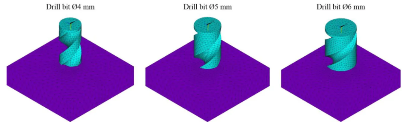
In order to study the drilling process on the bone tissue under different drill bit diameters, three models of the cutting tool were constructed with the 3D computer-aided design (with 4, 5 and 6mm of diameter, point angle of 118º and helix angle of 30º). Afterwards, its IGES file formats were imported into the FE code using ANSYS program, and integrated with the bone model with a square shape (16x16x4 mm) to simulate the drilling process (Figure 1).Each model was modelled using solid elements with eight nodes and the element size was defined under the point of view of both accuracy and time efficiency forthe calculation. Based on previous meshes analyses [14]-[16], and our previous studies [6], [8] two element sizes were considered in order to assure the mesh independent results, the calculation accuracy and to reduce computational requirements (CPU, RAM and running time). Since the high stress gradients would rise in the drilling region and its surrounding areas, a mesh discretisation was applied in this zone with an edge length of 0.5 mm. While the remaining model, a low mesh density was enough with an edge length of 1 mm. The overall FE models are shown in Fig 1.
Considering a conventional drilling operation, cutting tools have a rotary motion (drill speed) and feed movement (feed-rate), while workpiece is fixed on the bottom during the drilling process. In order to study the drill bit diameter effect, dynamic explicit analyses were carried out using a constant drill speed and feed-rate equal to 600 rpm and 1.25 mm/s, respectively. Due the high computational effort, only a feed depth equal to 4 mm was simulated. Also the thermal issues are not accounted in these models, due the numerical calibration obtained at distance equal to 3.5mm to the hole edge perforation, and the drill thermal effect in this vicinity vanish.
and to "separate" the material virtually by failure strain criterion [17]-[19]. Cowper-Symonds material model as well as the mechanical properties used in our numerical models have already been successfully applied and described [6], [8].The drill bit was modeled as a rigid body in order to reduce the computing time and resources.
Fig. 1 FE models for the three different drill bit diameters
The interaction between work piece and tools was modelled using the surface to surface contact eroding algorithm. The use of this contact is recommended whenever solid elements involved in the contact definition are subject to erosion due to failure criteria. Contact surface is updated as elements on free surface are deleted according to material failure criteria, in this work considered as the Failure Strain equal to 0.05.The frictional contact between the drill bit and block was modelled with a constant friction coefficient of 0.3, which had been used by other authors [20]. Also, time step size is automatically adjusted to satisfy the contact between different bodies and the program checks all elements when calculating the required time step. The time end of the present FE models was 6s.
3. Experimental Model
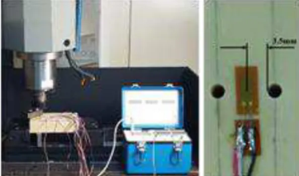
The FE models validation was made using experimental tests with solid polyurethane foam materials. This biomechanical test material was produced by Sawbones (Model #1522-27, 180×130×40 mm)and replicated the properties of human cortical bone (with closed cell with density of 0.80 g/cm3). In order to validate the FE models, three different drill bits were selected (4, 5 and 6 mm of diameter). All drills used in these experiments were conventional HSS twist drill bits. Following the numerical drilling parameters, all holes were performed with a drill speed of 600 rpm and feed-rate of 1.25 mm/s. A drilling depth of 30 mm was set for each diameter. The drilling tests were performed using a CNC machine. Experiments were performed at room temperature without cooling as in real orthopaedic surgery. The magnitudes of strain were controlled by the linear strain gauges (1-LY18-6/120, 120Ω ± 0.35% from HBM), which allowed the calculation of the corresponding profiles of stresses. The external surface of the bone block was properly clean and instrumented with fifteen strain gauges. The strain gauges were glued and positioned close to the drilling zone (approximately 3.5 mm between the edge of the hole and the strain gauge), as it is shown in Figure 2. A Model P3 Strain Indicator and Recorder (Vishay Precision Group, Inc., PA, USA) was used to collect the results. Recordings obtained from the one quarter Wheatstone bridge transducer allowed to read the strains on different material positions along the time, for each used twist drill diameter (4, 5 and 6 mm).Regarding to temperature in block surface, it has been demonstrated in previous studies that the temperature measurements, on the block top surface at 3.5 mm from the drilled zone, represent small values with no interference in the strain measurements [6]-[8]. The overview of the experimental setup used in this study is shown in Figure 2.
4. Results and Discussion
Fig.2 Experimental setup and strain gauges location
The obtained numerical results for the different drill diameters are compared, in terms of stress distribution during different steps of drilling. Significant differences are founded, showing the importance of considering an appropriate drill diameter in the drilling clinical surgeries. Figure 3 shows the von Mises stress distribution, chosen for a time instant equal to 3.2 s of drilling. This time corresponds to the time required for the complete depth of the block (4 mm), considering the feed-rate equal to 1.25 mm/s.
Fig.3 von Mises stress distributions (MPa) during drilling at time = 3.2 s, function of drill bit diameter
Figure 3 shows clearly the influence of drill bit diameter on the stress distribution. For the same time instant, the results showed that the increase in von Mises stress increased with the increase in drill bit diameter. Since all the other drilling parameters (drill speed, feed-rate, drilling time) are fixed, the explanation could be that the higher drill bit diameter increases the contact surface between the tool and material, leading to an increase of accumulated friction energy and, consequently, an increase of stress levels.
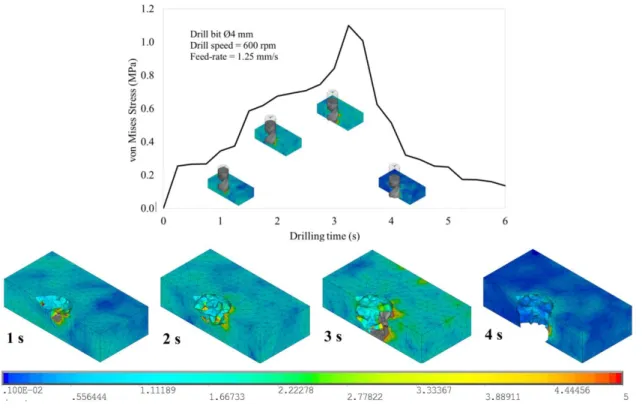
von Misses stresses for each step of drilling were also analysed. Figure 4 represents the typical curve of von Misses stress versus drilling time, considering the FE model with a drill bit of 4 mm. A set of nodal points was selected at a distance of 3.5 mm from the edge of drilled hole (according to the strain gauge position on experimental procedure) and the mean values were evaluated.
Mises stresses distribution were observed by Isbilira and Ghassemieha in their investigations of Titanium Alloy drilling [21]. Another aspect visible in the FE models is that maximum von Mises stresses are always located at the drilling zone and its immediate vicinity. Specially the maximum von Mises stresses appear at the intersection of drill bit helixes and hole margin, where the work material is undergoing higher equivalent strain.
Fig.4 Evolution of von Mises stress with drilling time
4.1 FE models Validation
In order to verify the results of the developed FE models, average experimental values of linear strain (𝜀𝑧𝑧) and the calculated normal stress (𝜎𝑧𝑧) from Hooke Law´s, in z direction, were obtained for 4 mm of drilling depth. Also in the numerical model, the values of strains and stresses were obtained with an average from each component, in the finite elements coincident with the strain gauge length position. This comparison is shown in the Figures 5(a) and (b). Figure 5(a) represents the mean and standard deviation of strains at three different drilling times (1, 2 and 3 s), and Figure 5(b) represents the mean of maximum normal stress obtained for the complete drilling depth (at 3.2 s). Both graphs show the results in accordance with the three drill bit diameters.
Figures 5(a) and (b) show that FE models provide a good approximation for strain and stress levels at different drill bit diameters. Figure 5(a) showed that the strains increase with drilling time, i.e. with tool penetration into the bone block, reaching a maximum value at end of the drill process. In Figure 5(b), the discrepancy between experiments and the FE models is less than 8%, as an average. This shows that the FE models can be used as a validated drilling model, according the obtained deviation value, and due to the agreement between all results. Comparing the levels of maximum normal stress for different drill bit diameters, it was observed that when the drill diameter was increased from 4 mm to 5 mm the stresses increased 17.68% and when the drill diameter was increased from 5 mm to 6 mm the stresses increased 14.8%.
5. Concluding Remarks
In this research,the effects of drill bit diameter on the stresses distribution during drilling were examined. Three FE elasto-plastic dynamic models which include complex drill bit geometries, constitutive model appropriate for high strain rate and drilling parameters were presented. Validation was carried out comparing numerical results and experiments and good accuracy was found. In summary, the results indicate that the use of an increased diameter in drill bit increases the contact surface between the cutting tool and the workpiece, which leads to a higher stresses level on the material. For all drill bit geometries, the stresses increase with the tool penetration and, consequently, with increasing of hole depth. It was verified that high stresses always appear at the intersection of drill bit helixes and hole walls regardless of the drilling parameters.
This work being a continuation of our previous studies using dynamic 3D FE drilling models, but it is the first one to predict the effect of drill bit diameter on stresses distribution during bone drilling with experimental validation. The present research could help surgeons have a better understanding of relation between cutting parameters and bone damage and the future consequences of inappropriate parameters. In advance, professionalscan thus better select the drilling parameters.
Acknowledgements
This research was supported by the Portuguese Foundation of Science and Technology under the research project UID/EMS/50022/2013. The third author acknowledges the funding of Project NORTE-01-0145-FEDER-000022 - SciTech - Science and Technology for Competitive and Sustainable Industries, cofinanced by ProgramaOperacional Regional do Norte (NORTE2020), through Fundo Europeu de Desenvolvimento Regional (FEDER).
Funding
This research received no specific grant from any funding agency in the public, commercial, or not-for-profit sectors.
References
[1] Zhang L, Tai BL, Wang G, Zhang K, Sullivan S, Shih AJ. Thermal model to investigate the temperature in bone grinding for skull base neurosurgery. Medical engineering & physics. 2013 Oct 31;35(10):1391-8. DOI:
http://dx.doi.org/10.1016/j.medengphy.2013.03.023.
[2] Tawy GF, Rowe PJ, Riches PE. Thermal damage done to bone by burring and sawing with and without irrigation in knee arthroplasty. The Journal of arthroplasty. 2016 May 31;31(5):1102-8. DOI: http://dx.doi.org/10.1016/j.arth.2015.11.002
[3] Lotfi M, Amini S. Experimental and numerical study of ultrasonically-assisted drilling. Ultrasonics. 2017 Mar 31;75:185-93. DOI: https://doi.org/10.1016/j.ultras.2016.11.009
[5] Wang W, Shi Y, Yang N, Yuan X. Experimental analysis of drilling process in cortical bone. Medical engineering & physics. 2014 Feb 28;36(2):261-6. DOI: https://doi.org/10.1016/j.medengphy.2013.08.006 [6] Fernandes MG, Fonseca EM, Jorge RN. Thermo-mechanical stresses distribution on bone drilling: Numerical
and experimental procedures. Proceedings of the Institution of Mechanical Engineers, Part L: Journal of Materials: Design and Applications. 2017 Jan 13:1464420716689337. DOI: https://doi.org/10.1177/1464420716689337
[7] Fernandes MG, Fonseca EM, Natal RJ. Thermal analysis during bone drilling using rigid polyurethane foams: numerical and experimental methodologies. Journal of the Brazilian Society of Mechanical Sciences and Engineering. 2016 Oct 1;38(7):1855-63. DOI: https://doi.org/10.1007/s40430-016-0560-4
[8] Fernandes MG, Fonseca EM, Natal RM. Three-dimensional dynamic finite element and experimental models for drilling processes. Proceedings of the Institution of Mechanical Engineers, Part L: Journal of Materials Design and Applications. 2015 Sep 29:1464420715609363. DOI: https://doi.org/10.1177/1464420715609363 [9] Gupta V, Pandey PM, Gupta RK, Mridha AR. Rotary ultrasonic drilling on bone: A novel technique to put an
end to thermal injury to bone. Proceedings of the Institution of Mechanical Engineers, Part H: Journal of Engineering in Medicine. 2017 Mar;231(3):189-96. DOI: https://doi.org/10.1177/0954411916688500
[10] Elangovan S, Allareddy V. Estimates of Hospital Based Emergency Department Visits due to Dental Implant Failures in the United States. Journal of Evidence Based Dental Practice. 2016 Jun 30;16(2):81-5. DOI: https://doi.org/10.1016/j.jebdp.2014.10.012
[11] Daokar SS and Agarwal G. Orthodontic Implant Failure: A Systematic review. International Journal of Oral Implantology& Clinical Research. 2016 Jan-Apr; 7(1):1-6.
[12] Pandey RK, Panda SS. Modelling and optimization of temperature in orthopaedic drilling: An in vitro study. Acta of Bioengineering and Biomechanics. 2014;16(1). DOI: https://doi.org/10.5277/abb140113
[13] Pandey RK, Panda SS. Drilling of bone: A comprehensive review. Journal of clinical orthopaedics and trauma. 2013 Mar 31;4(1):15-30. DOI: https://doi.org/10.1016/j.jcot.2013.01.002
[14] Alam K, Mitrofanov AV, Silberschmidt VV. Finite element analysis of forces of plane cutting of cortical bone. Computational Materials Science. 2009 Sep 30;46(3):738-43. https://doi.org/10.1016/j.commatsci.2009.04.035 [15] Lughmani WA, Bouazza-Marouf K, Ashcroft I. Drilling in cortical bone: a finite element model and
experimental investigations. journal of the mechanical behavior of biomedical materials. 2015 Feb 28;42:32-42. DOI: https://doi.org/10.1016/j.jmbbm.2014.10.017
[16] Li X, Zhu W, Wang J, Deng Y. Optimization of bone drilling process based on finite element analysis. Applied Thermal Engineering. 2016 Sep 5;108:211-20. DOI: https://doi.org/10.1016/j.applthermaleng.2016.07.125 [17] Asgharpour Z, Zioupos P, Graw M, Peldschus S. Development of a strain rate dependent material model of
human cortical bone for computer-aided reconstruction of injury mechanisms. Forensic science international. 2014 Mar 31;236:109-16. DOI: https://doi.org/10.1016/j.forsciint.2013.11.010
[18] Hernandez C, Maranon A, Ashcroft IA, Casas-Rodriguez JP. A computational determination of the Cowper– Symonds parameters from a single Taylor test. Applied Mathematical Modelling. 2013 Apr 1;37(7):4698-708. DOI: https://doi.org/10.1016/j.apm.2012.10.010
[19] Snedeker JG, Niederer P, Schmidlin FR, Farshad M, Demetropoulos CK, Lee JB, Yang KH. Strain-rate dependent material properties of the porcine and human kidney capsule. Journal of biomechanics. 2005 May 31;38(5):1011-21. DOI: https://doi.org/10.1016/j.jbiomech.2004.05.036
[20] Tu YK, Chen LW, Ciou JS, Hsiao CK, Chen YC. Finite element simulations of bone temperature rise during bone drilling based on a bone analog. J Med Biol Eng. 2013 Jan 1;33(3):269-74.