Universidade de Brasília
Instituto de Ciências Exatas Departamento de Ciência da Computação
An Architecture Conformance Process for Software
Ecosystems with Heterogeneous Languages
Sigfredo Farias Rocha
Dissertação apresentada como requisito parcial para conclusão do Mestrado Profissional em Computação Aplicada
Orientadora
Profa. Dra. Genaína Nunes Rodrigues
Brasília
2017
Ficha catalográfica elaborada automaticamente, com os dados fornecidos pelo(a) autor(a)
Ra
Rocha, Sigfredo Farias
An Architecture Conformance Process for Software Ecosystems with Heterogeneous Languages / Sigfredo Farias Rocha; orientador Genaína Nunes Rodrigues. -- Brasília, 2017. 61 p.
Dissertação (Mestrado - Mestrado Profissional em Computação Aplicada) -- Universidade de Brasília, 2017.
1. Conformidade Arquitetural. 2. Modelos de Reflexão. I. Rodrigues, Genaína Nunes, orient. II. Título.
Universidade de Brasília
Instituto de Ciências Exatas Departamento de Ciência da Computação
An Architecture Conformance Process for Software
Ecosystems with Heterogeneous Languages
Sigfredo Farias Rocha
Dissertação apresentada como requisito parcial para conclusão do Mestrado Profissional em Computação Aplicada
Profa. Dra. Genaína Nunes Rodrigues (Orientadora) CIC/UnB
Prof. Dr. Ricardo Terra Nunes Bueno Villela Prof. Dr. Rodrigo Bonifácio de Almeida
DCC/UFLA CIC/UnB
Prof. Dr. Marcelo Ladeira
Coordenador do Programa de Pós-graduação em Computação Aplicada
Dedicatória
Dedico esse trabalho aos meus pais, à minha amada esposa Jeissi e aos meus cachorros Scott e Lucy.
Agradecimentos
À UnB pela oportunidade.Aos meus superiores do Centro de Informática (antigos e atuais): Jacir Bordim, Marcelo Ladeira, Jorge Fernandes, Consuelo Martins e Riane Torres por todo apoio dado.
À minha orientadora Genaína Rodrigues que guiou com paciência e incentivo o meu crescimento nessa jornada.
Aos professores Rodrigo Bonifácio e Ricardo Terra cujas críticas possibilitaram a mel-horia do meu trabalho.
Ao colega Renato Edésio pela contribuição em vários momentos. Pelo apoio, dicas e feedback.
Aos meus colegas do PPCA que se alegraram e sofreram junto comigo nessa jornada: Renan, Fábio, Alan, Alysson e Reinaldo.
Resumo
Os custos de manutenção de software são fortemente influenciados pela sua conformidade com a arquitetura idealizada e boas práticas de desenvolvimento. A falta de conformi-dade gera gastos desnecessários. Ambientes heterogêneos com diferentes plataformas de desenvolvimento são ainda mais difíceis de manter conformidade devido à necessidade de lidar com diferentes técnicas e ferramentas. Este trabalho procura aliviar esse problema propondo um processo de conformidade arquitetural independente de plataforma. Téc-nicas de conformidade arquitetural são comparadas e uma avaliação é feita nos sistemas da Universidade de Brasília (UnB). Seis software foram avaliados, três deles implemen-tados em Java e os outros três implemenimplemen-tados em Visual Basic. O processo foi capaz de identificar com sucesso, violações arquiteturais em todos os diferentes sistemas usando a mesma técnica e ferramenta.
Palavras-chave: Conformidade arquitetural, DCL, Modelos de Reflexão, Conformidade
Abstract
The software maintenance costs are strongly influenced for its conformance with the con-ceptual architecture and the good development practices. The lack of such conformance generates unnecessary expenses. Heterogeneous environments with different development platforms are even more difficult to keep the conformance due to the need of dealing with different techniques and tools. This work aims to overcome this problem by proposing a platform independent software conformance process. Conformance checking techniques are compared and an evaluation was carried out in the Data Center at the University of Brasilia (UnB) systems. Six software systems were evaluated where 3 were implemented in Java and other 3 implemented in Visual Basic. The process was able to successfully iden-tify architectural constraints violations on all different systems using the same technique and tool.
Keywords: Architectural conformance, DCL, Reflexion models, Alloy software
Sumário
1 Introduction 1
1.1 Motivation . . . 1
1.2 Objectives . . . 2
1.3 Contributions . . . 2
1.4 Structure of the dissertation . . . 3
2 Background 4 2.1 Software Architecture . . . 4 2.2 Architecture Conformance . . . 5 2.3 Reflexion Models . . . 6 2.4 DSM . . . 7 2.5 Query Languages . . . 9 2.6 DCL . . . 9 2.7 Alloy . . . 11 2.8 Related Work . . . 12 3 Proposed Solution 16 3.1 Architecture Specification . . . 17
3.1.1 Architecture specification with Alloy . . . 18
3.1.2 Architecture Constraints on Alloy . . . 20
3.1.3 Architecture Specification with DCL . . . 21
3.1.4 Architecture Constraints on DCL . . . 21
3.2 Dependencies Extraction . . . 22
3.2.1 The Generic Language . . . 23
3.3 Conformance Analysis . . . 24
3.3.1 Alloy Conformance checking . . . 25
3.3.2 DCL Conformance Checking . . . 26
3.4 Result Output . . . 26
3.4.2 DCL Output . . . 29 3.5 Final Remarks . . . 29 4 Evaluation 30 4.1 Experiment Setup . . . 31 4.2 Results . . . 33 4.2.1 Violations . . . 35
4.3 Research Questions Analysis . . . 38
4.4 Threats to Validity . . . 39 4.5 Critical Analysis . . . 39 5 Conclusion 40 5.1 Future Work . . . 41 Referências 42 Appendix 45 A Alloy Syntax 46 A.1 Alloy Grammar . . . 46
B CPD Architectural Documentation 50 C Dependencies Extraction Output 57 C.1 Javadepextractor . . . 57
C.2 Vbdepextractor . . . 58
D Conceptual Architecture Files 60 D.1 Siex Architecture DCL File . . . 60
List of Figures
2.1 Conceptual and concrete architecture and its calls. . . 5
2.2 Reflexion model process [38]. . . 7
2.3 SAVE tool conformance checking results [14]. . . 8
2.4 Sigra system’s DSM obtained through the VBDepend Tool. . . 8
2.5 DCL syntax summary [3]. . . 10
2.6 Alloy 4.2 Tool. . . 11
2.7 Counterexample found shown on a graphic view. . . 12
3.1 Platform independent software architecture conformance process. . . 17
3.2 Architecture conformance analysis result example. . . 27
3.3 Console checking result of the Alloy model. . . 28
3.4 First Alloy counterexample found on the architectural conformance test of the Alloy model. . . 28
3.5 Second Alloy counterexample found on the architectural conformance test of the Alloy model. . . 28
4.1 CPD’s Java System Architecture Layer View. . . 31
4.2 CPD/UnB Visual Basic Systems Modular View. . . 32
List of Tables
2.1 Architectural conformance analysis approach comparative . . . 14
4.1 Goals for the experiment in GQM format . . . 30
4.2 CPD/UNB’s Layer Identifiers Nomenclature for Java Systems . . . 31
4.3 CPD’s systems used on the experiment . . . 33
4.4 Single constraint conformance checking tests running time . . . 33
Chapter 1
Introduction
Software Architecture is an abstract entity formed by elements and its relations. Each decision taken into its elaboration will affect the final product concerned to its depend-ability. Well planned documented, informed and managed architecture enables a better software quality because it allows a better action planning about its construction or evolu-tion. When these aspects are ignored, architectural erosions arise and as its consequence, technical debt from the perspective of architecture since the software will be modified without any type of control [43] [17]. The control over the corrective or evolutive code interventions on a software is not a trivial task. Not only it is hard to keep watching all the incoming modifications, but it is also difficult to read all the code in a non auto-mated way. A good awareness about the conceptual architecture and its supervision are quite sensitive to the developer team education and training. As result, forms of archi-tectural control, capable of identifying archiarchi-tectural problems and constraints violation are highly required and may facilitate these tasks as well as reduce drastically the costs of maintaining a software running.
1.1
Motivation
The Informatics Center (Centro de Informática - CPD) of University of Brasília (UnB) is responsible for implementation and management of the software that take over the academic tasks at UnB. Through the years, CPD has developed several systems and today it has a vast catalog (over 30 software systems). However, CPD has suffered some drawbacks common on government institutions: high turnover, lack of training, high amount of demands with stringent deadlines, technology and software aging. In particular dealing with software aging is a big challenge because it imposes increasing costs over software evolution and maintenance [40].
Moreover CPD still has to deal with different software each one developed either in Visual Basic, Java, VB.NET, C#, PHP, JavaScript and Erlang. In that context, it is very hard to implement monitoring polices to supervise the software evolution and guarantee its delivered quality. In particular with respect to architecture quality enforcement, a defined conceptual architecture built over good software practices still lacks. Keeping the software architecture conformance in such heterogeneous software development ecosystem [26] is crucial to ensure its dependability. At the beginning of this dissertation, as far as we are concerned, there was no implemented tool capable of doing software conformance analysis regardless of the programming language used. To achieve architecture conformance on the CPD systems, several tools and techniques should be used.
1.2
Objectives
This work proposes a solution capable of overcoming the necessity of using several tools and techniques to achieve the conformance on software ecosystems with heterogeneous languages. The objective is to create a software architecture conformance process able to use the same technique to identify the software architectural constraints violations.
1.3
Contributions
The software architecture conformance process is innovative by proposing and evaluating a technique capable of identifying architectural violations in different systems written in different programming languages. The dissertation contributions comprises:
• A technique capable of making conformance analysis of legacy systems with different languages.
• A process that permits the use of any conformance technique, where the most suit-able one might be used on each context. The process is composed by the following activities:
– Specification of the conceptual software architecture. – Declaration of the architectural constraints.
– Specification the concrete architecture abstracted from the source code. – Detection and report of the source code violations.
• An empiric evaluation of the platform independent conformance process using Alloy and DCL as well as its comparison.
1.4
Structure of the dissertation
The remaining chapters of this dissertation are organized as follows:
• Chapter 2 reviews the key concepts of the background of the dissertation: software architecture, architecture erosion and architectural conformance,
• Chapter 3 reviews the related work: Alloy language, DCL, DSM, Reflexion Models and SCQL.
• Chapter 4 proposes a platform independent architecture conformance process to support the heterogeneous environments management.
• Chapter 5 evaluates the conformance process in our implemented framework on 6 systems implemented at CPD.
Chapter 2
Background
2.1
Software Architecture
The software architecture is an abstract entity. It is formed by the software elements and its relations. Two of the biggest factors to increase the software costs are its evolution and customization [41]. Those factor are inevitable since the software modification is part of its life cycle. That is why the shape of this entity should not be underestimated, the requirements, architectural elements, design, security issues, algorithms and data types must be taken into account when making the software architecture design decisions to control its characteristics. Some already known and tested architecture styles like Layered System, Pipes and Filters, Event-based and Implicit Invocation [20] might be used as is or to build a customized new architecture. The software architecture is not a created object, every software has one, good or bad, it exists. A better term to talk about the decisions taking on its modifications is modeling. A good model of transmitting architectural knowledge, which is a difficult task since the software is usually a big and complex set of structures and relations, is the concept of views. A view is a vision of part of the software architecture when divided into relevant elements being evaluated [31] [11]. The concept of views is important because it groups only a part of the system’s elements and relations: The ones of interest of a specific concern. It makes easier to understand each specialized part. The combination of all architecture views, forms the full architecture. When modeling a software architecture, all decisions must be deliberate chosen, if not, there is a risk of imperceptible defects or performance issues arise. A well documented and informed architecture will keep a higher conceptual integrity, enable reuse more efficiently and better control [35].
2.2
Architecture Conformance
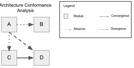
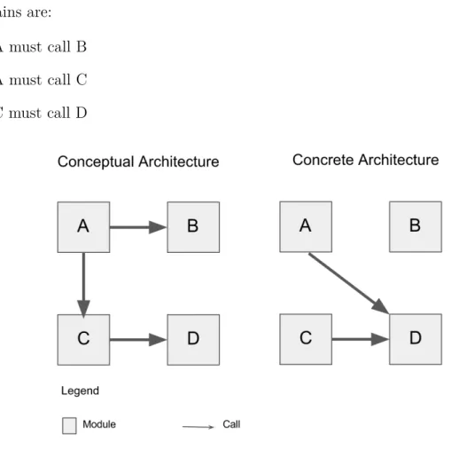
Architecture conformance is the name given to the syncronized association between the intended architecture for a software and its real architecture [29]. The lack of confor-mance happens for several factors like time pressure, the lack of technical knowledge and conflicting requirements. Some times these factors make the developer ignore the architectural rules and good software practices creating or increasing as consequence, ar-chitectural erosion [41]. In that way, the conceptual architecture documented and the concrete architecture existing as the source code structure does not relate anymore or has deviations between them. As an example Figure 2.1 shows a conflict between the soft-ware conceptual and concrete architecture. On the conceptual architecture the relation constrains are:
• A must call B • A must call C • C must call D
Figure 2.1: Conceptual and concrete architecture and its calls.
But as seen on the concrete architecture, module A might have needed some of the module D features and decided to call it directly creating a software erosion without even knowing. The conformance analysis will compare both models and identify the constraints defined by the conceptual model that were not satisfied by the concrete model. On a constraint checking over the example given, result is the following:
• A must call B (absent) • A must call C (absent) • C must call D (satisfied) • A call D (Not intended)
The hypothetical software has at this stage a software with a source code that will probably be harder to read and costly to evolve, it might also have worse performance.
There are basically two ways of checking for architecture conformance: statically and dynamically. Static approaches are non invasive, they are able to read the source code through a syntax searching for character sequences of interest or searching in the abstract syntax tree (AST) for specific elements. On the dynamic approach, the object of interest is the software instantiated objects and its relations whose behavior is lesser predictable and non measurable through source code analysis.
2.3
Reflexion Models
The reflexion model technique seeks to help the understanding and conformance analysis efforts in an iterative and empiric way [38]. A view of the process is shown on Figure 2.2, the technique uses a high level architecture model, a source code abstraction and a map-ping between these models. In possession of these artifacts, it is possible to compute a resulting reflexion model that exposes the absences, divergences and convergences found [37]. The technique might be applied through the steps below:
1. High level model definition: All the available information is used to create the architectural documentation with one or more architectural views.
2. Source code model extraction: Here, source code model extracting tools are used to build a lower level model.
3. Models Mapping: The architect declares the corresponding structures and relations between the high and low level models.
4. Reflexion Model computing: The reflexion model is then computed bringing as result the convergences, divergences and absences found in the low level model when compared to the high level model.
5. Refinement and investigation: The result is analyzed to verify if possible errors on the high or low level models definition had happened. After that, the source code problems are informed to the developer team.
Figure 2.2: Reflexion model process [38].
Some tools have been used to evaluate the technique [14] [37]. Figure 2.3 shows an example of conformance checking made by the SAVE tool [28]. The convergences are marked as a check mark in green background, the absenses are marked as a "X" red mark, the divergences are marked as a black exclamation point on an yellow background and finally unexpected relations are marked as a black question mark in a blue background.
2.4
DSM
The Dependency Structure Matrix (DSM) is a technique that helps analyze complex structures through a Matrix containing elements and its relations [9] [45]. It was first intended to be used on engineering design problems but it was found to be capable of helping to resolve several different problems, as it is the software analysis [43] [32] [44]. It has a simple structure composed by a matrix where the elements are disposed in a vertical line with a perpendicular horizontal line where the same elements are replicated. The Figure 2.4 shows a DSM taken from the Sigra system through the VBDepend Tool1.
Figure 2.3: SAVE tool conformance checking results [14].
The intersection cells are highlighted and numbered to indicate a dependency and its dependecy weight (how many calls were made).
The DSM Tools have the capacity of defining structural constraints which are indenti-fied in the congruent cells of the involved classes of a violation. The kinds of conformance check that the DSM is capable of doing are restricted to can-use and cannot-use types.
2.5
Query Languages
The Query Language (QL) is a language based on SQL and Database Theory [18] [13]. It is able to to make search queries over source code . It is intentionally similar to the SQL because it is a simple syntax and also on the effort to facilitate its learning since SQL is a well known language. An example is shown below where a query searches the entire project for the methods and then counts its lines of codes. The CQLinq [2] language was used.
1 J u s t M y C o d e . M e t h o d s
2 .Max( m = > m . N b L i n e s O f C o d e )
3 . T o E n u m e r a b l e () .Sum( loc = > loc )
The next example searches for a constraint violation (Fields name should start with lower case):
1 w a r n i f c o u n t > 0 (f r o m f in F i e l d s w h e r e 2 ! f . N a m e L i k e ( @" ^[ a - z ] ")
3 && ! f . I s E n u m V a l u e && ! f . I s T h i r d P a r t y 4 s e l e c t new { f }) . T a k e ( 1 0 )
SCQL [21] is one of its implementation, it is a domain specific language focused on using the relational queries to get version history information. The query languages were also used to query graphs that model hypertext [8].
2.6
DCL
The DCL (Dependency Constraint Language) [46] [47] [48], is a specific domain language that supports the system’s module definition in a declarative way. It is able to analyze architectural constraints through static analysis on the source code. It is inspired on the ideas of reflexion models [47]. The constraints are defined by a software architect and the conformance checking is made by the dclcheck tool [46] which is able to identify and exhibit the violations as absences and divergences in the source code. The violations are searched by comparing the source code model to the previously defined conceptual architecture with its software modules and constraints definitions.
The first thing on declaring the software’s architecture is its modules. In the DCL language this is done by the syntax:
module module_name: class_name1, class_name2, ... , class_nameN
The declaration supports several classes on one module, also the * character denotes that all classes on the given package belongs to the module being declared. These are some examples:
1 m o d u l e v i s i o n : br . unb . web . s i e x . v i s i o n .*
2 m o d u l e a c t i o n : br . unb . web . s i e x . v i s i o n . Action , br . unb . web . s i e x . b u s i n e s s
. A c t i o n B u s i n e s s
The next step is the constraints declaration, the Figure 2.5 shows a DCL’s syntax summary. The relation between two modules is declared with some types and modifiers. The "only" keyword is optional.
Figure 2.5: DCL syntax summary [3].
An possible example is:
1 o n l y V i s i o n can a c c e s s B u s i n e s s
This declaration restricts the access to module "Business" exclusively from module "Vision". In that way, for example if the "Persistence" or "Pojo" modules have a depen-dency call of the kind "access", the technique will classify it as a divergence. The "can" keyword indicates that module "Vision" can access "Business" but is not obliged to. If that was the case, then the "must" keyword should be used. The language is very simple and easy understandable, some other examples are given below:
1 V i s a o must-e x t e n d B a s e V i s a o 2 N e g o c i o must-i m p l e m e n t N e g o c i o I 3 V i s a o cannot-a c c e s s P e r s i s t e n c i a 4 P e r s i s t e n c i a cannot-d e c l a r e V i s a o
5 o n l y Visao , Negocio , P e r s i s t e n c i a can-a c c e s s Vo
The technique’s evaluation was done by case study on the Brazil’s Federal Data pro-cessing Service Organization (SERPRO) [47] where the personal management system were used to check for the approach validity. The authors evaluated 3 versions of the system and were able to successfully identify several architectural violations.
2.7
Alloy
Alloy is a declarative language based on first order logic capable of modeling and analyzing structure abstractions [24] [23] [1]. It is essentially a model finder because it uses the structure abstractions through declaration of formulas to build a model with the elements and relations satisfying the given formulas.
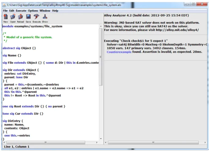
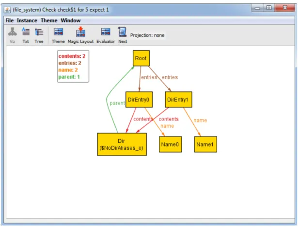
Alloy works as a simulator where it generates a sequence of states or transitions to satisfy a formula or as a checker where a counterexample that invalidates the formula being checked is searched. It is based and strongly influenced by the Z language and the Tiny Kernel language [24]. The Figure 2.6 shows the graphical mode of the tool being executed. The graphical view of the instance models found to invalidate a predicate or assertion is shown in Figure 2.7.
Figure 2.6: Alloy 4.2 Tool.
Alloy models are analyzable, the language has a formal semantics which makes it possible to be automatically analyzed. Its declarative syntax also helps to easily build complex specifications. The Alloy analyzer cannot guarantee a sound and complete anal-ysis, it works through the generation of possible instances within a scope. The numbers
Figure 2.7: Counterexample found shown on a graphic view.
of cases to consider has an exponential growth related to the scope size, so a scope lim-itation is necessary because if there is not one, the counterexample searching would be infinite. A relation in a scope of k has 2k∗k possible values [25]. The Alloy language mainly uses signatures declarations, facts, predicates and assertions to define and analyze models or simulate a model transitioning states. It reduces those elements and formulas into a boolean satisfiability problem (SAT) which is solved by the built-in SAT solver. The Alloy syntax is shown in Appendix A.
2.8
Related Work
Architecture description languages (ADLs) have been used as a form of specifying the software structures to support the reasoning about it. ACME [19] is an ADL capable of defining elements of component-based architectures, its efforts goes on the objective to in-tegrate architecture analysis tools. Darwin [34] is used to specify hierarchically structured architectures, it is possible to use primitive components to composite component types. Darwin deals with the components with what services they provide and what services they require. Related to our problem, the ADLs are not very suited because their goal is the
specifications of architectures to support the reasoning about its structures. Checkstyle has been used to recover and maintain architectural conformance, a software architecture supervision technique through custom checks on commit time was proposed by [36]. The approach was tested on the Tribunal de Contas da União (TCU). It uses static source code analysis, visitor pattern and Checkstyle2 tool custom checks to prevent architectural violations on their software. This approach is not suited to our context because it uses a specific tool to a specific programming language, it is a good option to homogeneous environments.
CQLinq [2] is a query language based technique that is used to obtain software metrics and conformance rules checking through customized queries. To our context, the CQLinq is not very suited since, there is no architecture abstraction and each constraint definition is more complex then other approaches.
The SAVE tool [28] is a reflexion model technique capable of comparing high level models to identify deviation between them. It has been used to the conformance analysis, the tool is also used on a proposal of continuous monitoring [29]. The tool might have difficulty on working with several languages simultaneously, it is also less expressive than other approaches such as DCL.
A comparison between three conformance analysis approaches (Reflexion Model, Re-lation Conformance Rules and Component Access Rules) are done by [30]. They use an implementation of the SAVE tool to evaluate its characteristics. The downside of this work is the strong bonding to the SAVE tool, there is too low possibilities of customization.
ISO/IEC 42010 [15] is a normative guidance that standardize the notion of archi-tecture framework. It define requirements like viewpoint models, relation expressing and correspondence between models to be used by architecture frameworks. This normative is a good basis to influence software conformance checking frameworks, but it is too generic, further exploration is needed to access its importance.
The Alloy language has been used to several conformance analysis, the two more related to the problem studied are the works by Garlan and Kim where they use the Alloy to analyze architectural styles properties [27] and Crane and Dingel where they make dynamic runtime conformance checking of objects [12]. Alloy has also been used to analyze UML runtime models [49] and system acess control testing [22]. As far as we are concerned, Alloy has never been used to check software conformance on a static fashion like DCL, SCQL and DSM approaches.
The architecture enforcement with the Checkstyle API is used on a slightly different context, it is used strictly on software written in Java and it is a complex technique when compared to the other ones being analyzed. The ArchLint is a tool capable of
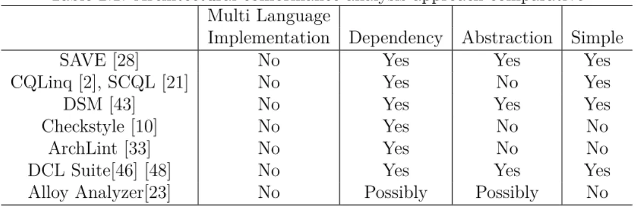
extracting a software’s architectural knowledge through the static analysis of source code history in the software repository. It is able to understand deeply the architecture but it is complex and lacks abstraction. The SCQL also lacks abstraction. It is less complex to use then ArchLint for example but compared to the others approaches like DCL it is more complex. Its strength is the capability of searching structures on the source code through queries which are high customizable. DSM is language-independent, some tools already use them to abstract software architecture [5] [6]. It is very simple to use and understand. Its downside is the low expressiveness. The DCL language uses Reflexion Models concepts, that is why both has several common characteristics, their concepts are easily portable, they are capable of modeling structures on a high level abstraction and checking architectural constraints on the source code. The differential is that DCL language is more expressive, it allows declaration of more type of relations like for example implement, create, throw and extend. Alloy is a model checker that is able to define and analyze structure and its relations. It have never been used to make software conformance analysis through static source code analysis so an investigation about this possibility is done through the evaluation. We summarized the result of our study on Table 2.1
Table 2.1: Architectural conformance analysis approach comparative Multi Language
Implementation Dependency Abstraction Simple
SAVE [28] No Yes Yes Yes
CQLinq [2], SCQL [21] No Yes No Yes
DSM [43] No Yes Yes Yes
Checkstyle [10] No Yes No No
ArchLint [33] No Yes No No
DCL Suite[46] [48] No Yes Yes Yes
Alloy Analyzer[23] No Possibly Possibly No
The Multi Language Implementation column answers if the technique has a concrete implementation able to work on different developing platforms with its different program-ming languages. Most techniques are able to make the conformance analysis on different languages but using different implementations. The column is related to if there is an implemented version capable of dealing with any language, the answer "no" is given to the technique which have no tools or scientific work proving the concrete application of the technique implementation on different platforms. In the Dependency column it is analyzed if the technique is able to check dependency constraints between modules. The "Possi-bly" answer is given to the technique potentially able but not used for this objective yet. Abstraction Is related to the technique’s ability to promote higher levels of abstraction of the architecture components. The abstraction allows lowers the architectural confor-mance process effort by facilitating the understanding of the structures and relationships
of the software. The last column (Simple) is related to if it is easy is to understand and use the technique or not.
Chapter 3
Proposed Solution
In this chapter we present the core of our work towards an architecture conformance pro-cess for software ecosystems with heterogeneous development languages. The proposed process is capable of identifying deviations of the software source code from the specified conceptual architecture. It uses the same technique to analyze the architectural confor-mance of software with different programming languages. The process relies on source code documentation patterns as well as architecture specification, constraints defined by the architect and the source code extracted architecture. The violations revealed by our reflexion based process are informed to the practitioner.
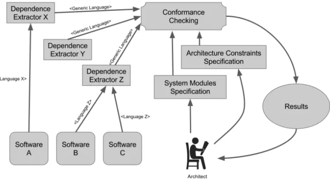
The reflexion process proposed starts by the specification of the architectural elements, then acquiring the source code elements, making the conformance analysis and finally showing the results. It comprises 5 steps:
• Architecture Specification: The architect must define the conceptual architecture rules, its modules, constraints and requirements.
• Dependence Extraction: The source code dependency extraction provides the con-crete architecture view. The dependency file must be written on a single language independent of the programming language used to build the software.
• Conformance Checking: The translated model is checked over the conceptual archi-tecture defined. All deviations between the models are captured.
• Result Output: The architecture conformance result must informe through the tex-tual or visual exhibition, the deviations found and what are its kind (absence or divergence).
Figure 3.1 shows the process view, each process step is further explained in the next subsections and evaluated in Chapter 4.
Figure 3.1: Platform independent software architecture conformance process.
3.1
Architecture Specification
This is the first step of the process. It is responsible for the "System Modules Specifica-tion" and "Architecture Constraints SpecificaSpecifica-tion" boxes of Figure 3.1. It takes as input the definition of an architect and all the documentation and knowledge existent. The ar-chitect is important because he is the responsible for defining the conceptual arar-chitecture documentation. If there is no architect, an experienced developer might assume the role. An architecture documentation is composed by several different views so, the architect must be able to define what kind of view will have its constraints checked. For exam-ple the layering view has the definition of the layers and how they communicate to each other, which ones are allowed or forbidden to make a dependence call to a specific layer. This modeling of an architectural view is important to allow a higher level of abstraction about the software, it is easier to understand and verify the architectural aspects that way. To fit on the proposed process, the conceptual architecture of all software present on the ecosystem must be specified on a singular language. Any language might be used as long as it is able to specify the architectural elements definition and their mapping to the source code artifacts. Also all architecture constraints must be specified.
With the software documentation in hands, the architect must specify on the chosen specification language, the software division (modules or layers) and its relation con-straints. Those information compose the output of this step, the specified conceptual
architecture.
3.1.1
Architecture specification with Alloy
The Alloy model must be capable of defining the modules, the relations between them and its constraints. A Java project1 was created to test several Alloy models with different formats. The most efficient modeling was the one structured in the following format:
1 m o d u l e p r o j e c t _ n a m e 2 3 sig C l a s s {} 4 sig L a y e r _ n a m e _ A , L a y e r _ n a m e _ B { c l a s s e s : set C l a s s } 5 sig C l a s s _ n a m e _ A , C l a s s _ n a m e _ B e x t e n d s C l a s s {} 6 sig R e l a t i o n _ t y p e _ 1 , R e l a t i o n _ t y p e _ 2 { r : set C l a s s - > C l a s s } 7 8 f a c t { L a y e r _ n a m e _ A . c l a s s e s = C l a s s _ n a m e _ A + C l a s s _ n a m e _ X } 9 f a c t { L a y e r _ n a m e _ B . c l a s s e s = C l a s s _ n a m e _ B + C l a s s _ n a m e _ Y } 10 11 f a c t { R e l a t i o n _ t y p e _ 1 . r = C l a s s _ n a m e _ A - > C l a s s _ n a m e _ B } 12 f a c t { R e l a t i o n _ t y p e _ 2 . r = C l a s s _ n a m e _ X - > C l a s s _ n a m e _ Y }
The first line has the Alloy module definition, the syntax might be confusing when the dependencies between modules are being analyzed. This kind of module is a higher Alloy project division, like a package in the Java syntax. On the tests made, since it is used a simple layering architecture, the lower level modules are called "layer". The module declaring has the following syntax:
1 m o d u l e s y s t e m _ n a m e
Example:
1 m o d u l e s i s r u
Or
1 m o d u l e s i e x
On the line 3, the Class model type is declared as a signature, it was named "Class", it will be inherited by all the Classes. It might be seen as a super Class of all the Classes declared on the model.
On line 4, all the modules (the layers in this particular case) are declared, each one has a set of classes inside it. They will later be populated with the relevant classes. The layer declaration is done like the example below:
1 sig vision , b u s i n e s s , p e r s i s t e n c e , p o j o { c l a s s e s : set C l a s s }
The classes are declared on line 5 on a straightforward way: the class qualified name followed by the higher set (the super class) extension:
1 b r _ u n b _ w e b _ s i e x _ v i s a o _ M a n t e r P r o p o s t a L i s t a g e m V i s a o e x t e n d s C l a s s {}
The full syntax is seen on the example below:
1 sig b r _ u n b _ w e b _ s i e x _ v i s a o _ M a n t e r P r o p o s t a L i s t a g e m V i s a o ,
b r _ u n b _ w e b _ s i e x _ n e g o c i o _ A l o c a M e m b r o E x t e n s a o N e g o c i o e x t e n d s C l a s s {}
On Line 6 the relations types are declared, each one of them has a set of of relations between classes. This is how the dependency type will be identified. Example:
1 sig Access , Declare , C r e a t e { r : set C l a s s - > C l a s s }
The layers are then populated on lines 8 and 9 through Alloy facts. The nomenclature pattern and packages used on the university’s systems help to identify from where each class comes from. The pattern is shown in Table 4.2 of Section 4.1. This knowledge helps the testing tool to obtain automatically the classes layer. Binary relations are used on the form "A: B" or "A: B + C + D" when declaring several relations. Concrete examples on the layer populating are:
1 f a c t v i s o n { L a y e r . v i s o n = I n s c r i c o e s C o n f i r m a d a s V i s a o + 2 R e p l i c a r P r o p o s t a V i s a o }
or
1 f a c t b u s i n e s s { L a y e r . b u s i n e s s = M a n t e r P r o g r a m a T o p i c o N e g o c i o + 2 M a n t e r E d i t a l N e g o c i o I m p l }
Lines 11 and 12 show the dependencies declaration form. The relations are declared through ternary relations on the form "A: B -> C ". Where A is the variable holding all dependencies and B and C are respectively the classes making a method call and receiving the method call. A variable was declared before to identify each kind of relation. The appropriate one is used on this step. Below, an example is given:
1 f a c t { A c c e s s . r = b r _ u n b _ w e b _ s i e x _ v i s a o _ M a n t e r P r o p o s t a L i s t a g e m V i s a o - > b r _ u n b _ w e b _ s i e x _ n e g o c i o _ A l o c a M e m b r o E x t e n s a o N e g o c i o + b r _ u n b _ w e b _ s i e x _ p e r s i s t e n c i a _ C e r t i f i c a d o D A O I m p l } 2 3 f a c t { I m p l e m e n t . r = b r _ u n b _ w e b _ s i e x _ p e r s i s t e n c i a _ M a n t e r A v a l i a c a o D A O I m p l - > b r _ u n b _ w e b _ s i e x _ p e r s i s t e n c i a _ M a n t e r A v a l i a c a o D A O + b r _ u n b _ w e b _ s i e x _ p o j o _ P a r e c e r e - > j a v a _ i o _ S e r i a l i z a b l e }
The Alloy architecture specification, must be manually defined by the architect. The Alloy architecture model is very extensive and verbose, for this reason, the modules and classes information were inserted on the Alloy testing tool so it could extract some of the information automatically. The file generated is in fact very extensive (35 lines and
187333 columns of characters), part of it may be seen on Appendix D. The declarations types used are: access, declare, create, extend, implement, throw and useannotation.
3.1.2
Architecture Constraints on Alloy
An Alloy fact is an affirmation that always holds a true value. The Alloy assertive is different, it holds an affirmation that will be checked. The architectural constraints fits well in this definition, the architect must be capable of transforming the documentation’s information into Alloy assertive. An Alloy assertive has the following syntax:
1 a s s e r t A s s e r t _ n a m e {
2 all x : class_A , y : c l a s s _ B | y in x . v a r i a b l e s }
Where assert is the Alloy identifier for the assertive and inside the brackets there is a formula to be checked by the analyzer. For example, the Java layering view (Appendix B) specifies that no vision class can access directly a persistence class. One possible example is: "No class from vision can create a class from persistence". On Alloy syntax we have:
1 no x : L a y e r . vision , y : L a y e r . p e r s i s t e n c e | x - > y in C r e a t e . r e l a t i o n s
Being "relations" the variable holding all the dependency calls between the software classes of that type of relation.
Another example: "no class from persistence can implement a class from business":
1 no p : L a y e r . p e r s i s t e n c e , b : L a y e r . b u s i n e s s | p - > b in I m p l e m e n t . r e l a t i o n s
The full assertion declaration uses the assertion syntax with the constraint formula inside it. It will be later checked by the check command. The concrete example is given below:
1 a s s e r t n e g o c i o _ v i s a o {
2 no x : L a y e r . vision , y : L a y e r . p e r s i s t e n c e | x - > y in C r e a t e . r e l a t i o n s
3 }
To effect of the evaluation, the constraint "No vision class may access the persistence layer classes" was used. This assertive was included on the Alloy architecture file and it was translated to the following syntax:
1 a s s e r t n o _ v i s a o _ p e r s i s t e n c i a {
2 no x : v i s a o . classes , y : p e r s i s t e n c i a . c l a s s e s | x - > y in A c c e s s . r
3 }
Part of the file is disposed on the Appendix D, the full file is generated by the class "GenericToAlloy.java" available on the Alloy testing tool.
3.1.3
Architecture Specification with DCL
The DCL Architecture file is a .dcl extension file containing the architecture written in the dcl language informing the software’s modules and its constraints. It is important to note that the modules cited here are different from Alloy modules. DCL modules are parts of the software grouped by affinity, like layers as the examples seen so far. The DCL architecture file is shaped in the way showed below:
1 m o d u l e M o d u l e _ A _ n a m e : C l a s s _ A _ n a m e 2 m o d u l e M o d u l e _ B _ n a m e : C l a s s _ B _ n a m e
Line 1 and 2 contain the module declaration. Each class name belonging to a module or the whole package must be declared as components of a module. The declaration is very straightforward. An example containing both cases is show below:
1 m o d u l e v i s i o n : br . unb . web . s i e x . v i s a o . I n s c r i c o e s C o n f i r m a d a s V i s a o 2 m o d u l e b u s i n e s s : br . unb . web . s i e x . n e g o c i o .*
It is also possible to use regular expressions to get the right classes through its nomen-clature pattern, like this:
1 m o d u l e v i s a o : " br . unb . web . s i e x . v i s a o .[ a - zA - Z0 - 9 / . ] * V i s a o "
To exemplify the software architecture specification on dcl, the created documentation of the Java systems (using Siex as the test case) was used. The file is transcribed next 2:
1 m o d u l e $ s q l : j a v a . sql 2 m o d u l e v i s a o : " br . unb . web . s i e x . v i s a o .[ a - zA - Z0 - 9 / . ] * V i s a o " 3 m o d u l e b a s e v i s a o : br . unb . f a s t . c o r e . c a m a d a . v i s a o . B a s e V i s a o 4 m o d u l e n e g o c i o : " br . unb . web . s i e x . n e g o c i o .[ a - zA - Z0 - 9 / . ] * N e g o c i o I m p l " 5 m o d u l e b a s e n e g o c i o : " br . unb . web . s i e x . n e g o c i o .[ a - zA - Z0 - 9 / . ] * N e g o c i o " 6 m o d u l e i c r u d n e g o c i o : br . unb . f a s t . c o r e . c a m a d a . n e g o c i o . I C r u d N e g o c i o
7 m o d u l e b a s e p e r s i s t e n c i a : " br . unb . web . s i e x . p e r s i s t e n c i a .[ a - zA - Z0 - 9 / . ] * DAO " 8 m o d u l e p e r s i s t e n c i a : " br . unb . web . s i e x . p e r s i s t e n c i a .[ a - zA - Z0 - 9 / . ] * D A O I m p l " 9 m o d u l e d a o f a c t o r y : br . unb . web . s i e x . p e r s i s t e n c i a . D A O F a c t o r y 10 m o d u l e p o j o : br . unb . web . s i e x . p o j o .* 11 m o d u l e vo : br . unb . web . s i e x . vo .*
3.1.4
Architecture Constraints on DCL
The constraint declaration follows the model shown below:
1 ( m o d i f i e r ) M o d u l e _ A _ n a m e ( v e r b ) ( r e l a t i o n _ t y p e ) M o d u l e _ B _ n a m e
Or:
1 C l a s s _ B _ n a m e cannot-a c c e s s C l a s s _ A _ n a m e 2 o n l y C l a s s _ A _ n a m e can-c r e a t e C l a s s _ B _ n a m e
Where the modifier is optional, the verb is one of the DCL’s operators verbs like can, cannot and must and the relation_type is the kind of relation between the classes, for example access, throw, extend and depend. Some examples are:
1 V i s i o n can a c c e s s B u s i n e s s
2 V i s i o n c a n n o t a c c e s s P e r s i s t e n c y 3 V i s i o n m u s t e x t e n d B a s e V i s i o n 4 P o j o c a n n o t d e p e n d Vo
5 o n l y B u s i n e s s can t h r o w B u s i n e s s E x c e p t i o n
The Siex constraints specified for the evaluation is shown next on a transcription of the DCL architecture file 3:
1 v i s a o must-e x t e n d b a s e v i s a o 2 n e g o c i o must-i m p l e m e n t b a s e n e g o c i o 3 o n l y negocio , d a o f a c t o r y can-c r e a t e p e r s i s t e n c i a 4 b a s e n e g o c i o must-e x t e n d i c r u d n e g o c i o 5 o n l y p e r s i s t e n c i a can-a c c e s s $ s q l 6 n e g o c i o cannot-a c c e s s v i s a o 7 o n l y negocio , d a o f a c t o r y can-a c c e s s p e r s i s t e n c i a 8 o n l y negocio , d a o f a c t o r y can-a c c e s s b a s e p e r s i s t e n c i a 9 p e r s i s t e n c i a must-i m p l e m e n t b a s e p e r s i s t e n c i a 10 p e r s i s t e n c i a cannot-a c c e s s visao , n e g o c i o
11 p o j o cannot-a c c e s s visao , negocio , p e r s i s t e n c i a , vo 12 vo cannot-a c c e s s visao , negocio , p e r s i s t e n c i a
3.2
Dependencies Extraction
The source code dependency extraction provides the view of how the concrete software architecture is structured. This step is related to the "Dependence Extractor" boxes in Figure 3.1, its inputs are the software source codes. Each software programming language has its own structuring characteristics and operation, anyhow a single language must be used in a sense that the extraction output have the same syntax independent of the software’s language. The information of interest to the evaluation are the software dependencies which will be a view of the concrete architecture of the source code. The dependence file must contain the information about the class calling, the class called and 3The transcription has only the constraints, the part with the modules were already shown in subsec-tion 3.1.3
what kind of dependence is that. It might be access, implementation or creation for example.
To extract the software dependencies, the project’s source code must be walked check-ing each line if there is a dependence call to another class. All the dependencies found must be included on the output file. To convergence of several languages on a single one, a simple generic language is used. It is further explained on the next section.
3.2.1
The Generic Language
To use the same kind of conformance analysis, it is necessary a language conversion step. It might happen either inside the analysis tool or on the dependence extracting task. To converge inside the analyzer, it is necessary to deal and translate a huge number of possible tools output. We develop an extractor able to export the dependencies extraction on the desired format for each different programming language. The output proposed for the dependency extraction step is the one given by a simple generic language. This language has the most simple and objective information required:
• The class making the call • The class receiving the call • The type of the call
The required information is separated by comma and the dependencies types used on this dissertation are: Declare, Access, Create, Extend, Implement, Throw and Useanno-tation. The language has the following format:
1 M o d u l e _ A , d e p e n d e n c y _ t y p e , M o d u l e _ B
A practical example is given by the following AbrirCaixaVisao4 class source code:
1 @ N a m e d 2 @ S e s s i o n S c o p e d 3 4 p u b l i c c l a s s A b r i r C a i x a V i s a o e x t e n d s B a s e V i s a o { 5 6 @ E J B p r i v a t e C a i x a N e g o c i o c a i x a N e g o c i o ; 7 p u b l i c S t r i n g g e t D i s p l a y A b r i r C a i x a () { 8 C a i x a u l t i m o C a i x a A b e r t o = 9 c a i x a N e g o c i o . b u s c a r C a i x a A i n d a A b e r t o ( 10 c o d i g o P e s s o a L o g a d o ) ; 11 } 12 }
4To a better exhibition, the class was edited to keep only the necessary elements. It was taken from the University of Brasília’s restaurant system (Sisru)
The class segment above holds the following dependency on the generic language syntax:
1 A b r i r C a i x a V i s a o ,access, C a i x a N e g o c i o
The complete version of the dependency must contain the qualified class name informing its package hierarchy, this is important to identify and divide the software modules. The qualified version is:
1 br . unb . web . s i s r u . v i s a o . A b r i r C a i x a V i s a o ,access, br . unb . web .
2 s i s r u . n e g o c i o . C a i x a N e g o c i o
The conformance analysis tool must be able to deal with this language to compare the concrete architecture with the conceptual architecture specified on its the tool’s descrip-tion language.
CPD has mainly Java and Visual Basic systems. As far as we are concerned there was no Visual Basic dependency extracting tool able to output the dependencies on a textual format close to the one used by the generic language. A Visual Basic dependency extractor was then implemented 5 specifically to evaluate this work. The extractor was build using the university systems characteristics to get the dependencies and export them to a textual file written on the generic language. To better understanding the output and its format, the first page of the file generated by the vbdepextractor when getting the University of Brasília Academic system (Sigra) is shown in Appendix C. To extract the Java software dependencies, a third party tool6 was already implemented which gives the result output on the generic language. javadepextractor was used to acquire the dependencies of Java source code. The tool has as input the project directory path, the output is given in a text file (.txt) containing the dependencies written in the generic language. The Appendix C contains the first page of a file generated by the tool when it extracted the dependencies of the University’s academic extension system (Siex). On its evaluation, no problem was identified in its output.
On both tools, the output is given on a text file called dependencies.txt which is written on the generic language syntax. The Appendix C has more information about the files extracted. All the original files may also be found on the Git repository7.
3.3
Conformance Analysis
On this stage the conceptual architecture model with the modules definitions and its restrictions are used to guide the searching for the source code violations. The
"Confor-5https://github.com/Sigfredo/vbdepextractor 6https://github.com/rterrabh/javadepextractor 7https://github.com/Sigfredo/Unbconformancefiles
mance Checking" box on Figure 3.1 is related to this step. As was presented, the inputs to this step are the outputs of the previous steps: The file containing the system mod-ules and architecture constraints specification as well as the file containing the source code dependencies on the generic language. Several conformance techniques exist using different operations and each context might demands a different one. Aspects like the capability of analyzing dependencies between modules, if it is platform independent, the level of source code modification, easiness of use and results intelligibility are aspects that might be taken into account when choosing a technique. The way the techniques check for constraints violation vary, for instance DCLcheck uses static code analysis to search for string patterns that are compared to previous defined modules. Alloy Analyzer transform the specified constraint formulas into a SAT problem, it is ran by a built-in SAT Solver to generate models using the module signatures and facts together with the constraint assertive. It searches for a counterexample model, if it finds, the constraint being analyzed is invalidated.
The process does not imposes a restriction related to what technique will be used but might be necessary on some cases, adapting the chosen one to deal with the dependencies file written on the generic language syntax. There is no need of adapting the conceptual architecture definition since when choosing a technique, the conceptual architecture spec-ification will be already defined on its syntax. An Alloy testing tool8 was constructed to test the Alloy models and conformance checking. It is also capable of transforming the generic language into Alloy syntax. The pi-dclcheck is a DCL tool that already deals with the generic language so, there is no need of adaptation when using it.
The output given by this step is the result of the conformance checking, which con-straints were violated and by what dependencies defined on the source code extraction file.
3.3.1
Alloy Conformance checking
The proposed process uses the Reflexion Model concepts to verify the software architec-ture conformance, identifying its constraints violations. Since only the divergences and absences are of interest, an Alloy assertive must be declared as a restriction or absence check returning true or false to each assertive declared, it is important to note that the Al-loy Analyzer is not capable of checking multiple assertive with one command. The check command analyze a single assertive given reducing it and all the signature declaration and facts to a SAT problem. It returns true or false depending on if it was able to find a counterexample or not in the scope given. The case being tested has 2 variables being related to each other so, a scope of 2 is used. The checking command, after executed will bring the result in two ways:
1 C o u n t e r e x a m p l e f o u n d. A s s e r t i o n is i n v a l i d.
Meaning that the assertive is certainly invalid, or the affirmation phrase given is false.
1 No c o u n t e r e x a m p l e f o u n d. A s s e r t i o n may be v a l i d.
As no counterexample was found, the assertive probably is valid. It is not possible to claim that the assertion is always true. But it is true inside the limit given (the scope). That is way Alloy is a scope complete analyzer. In the case given, the scope 2 was chosen so, it is possible to claim that the assertive is certainly true in the scope of 2.
The constraint checking command below was used to verify the conformance:
1 c h e c k n o _ v i s a o _ p e r s i s t e n c i a for 2
3.3.2
DCL Conformance Checking
The DCL’s conformance checking uses 2 files, one containing the module declaration and one containing the dependency calls. The tool pi-dclcheck 9 has the feature of reading the files written in the generic language syntax so that is the one used on this work.
The pi-dclcheck tool populate the modules and dependencies. After that, it checks for the constraints rules in the dependencies set. Its output is given in a textual file called violations.txt created in the folder path given as input.
With the generated files on the previous process steps ready (architecture.dcl and dependencies.txt), the tool’s execution command was used:
1 j a v a - jar pi - d c l c h e c k a r c h i t e c t u r e . dcl d e p e n d e n c i e s . txt
After the execution a text file is generated containing the information of the violations found.
3.4
Result Output
The result output is given with the information about what deviations were found on the concrete architecture when compared to the conceptual architecture. The relations of interest are the ones given by any reflexion model inspired approach: the convergences, divergences and absences found in the extracted architecture from the source code when compared to the conceptual architecture defined by the architect. Figure 3.2 shows the information of interest. Although all these information are important to understand the software, on our context, the convergences where not relevant so they are ignored by the results.
There are basically two forms of exhibiting the conformance checking results: Through visual exhibition and through textual information. DSM and Alloy inform the constraints violations through a visualization of models generated by the concrete architecture and the conceptual constraints on the Alloy case and on a Matrix with converging cells on the DSM case. DCL and Reflexion Models output is simple, straightforward and also very informative. It tells through a textual form, which kind of violation was found, the caller and the called class and also what type of call was the one that violated the analyzed constraint. With this information, the developer team is capable of doing a guided source code adjustments.
Figure 3.2: Architecture conformance analysis result example.
3.4.1
Alloy Output
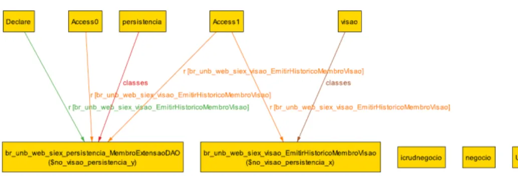
The information given by the Alloy Analyzer console can be seen in Figure 3.3. The analyzer information shows the time taken to prepare the variables and searching for counterexamples that invalidate the constraint specified on the assertive. Figures 3.4 and 3.5 show counterexamples found, it is possible to see that the "EmitirHistoricoMembro-Visao" is the dependence that violates the constraint on both cases. The Alloy analyzer does not show all the relations violating the constraint, it might show but as its operation mode works, it stops if finds a counterexample instance breaks the assertion. As so, it might show only one violation, which were all the cases we found. Its objective is to tell if an assertion holds or not. Chances are that the result show all the violations on a single counterexample, but it is impossible to predict, if enough counterexamples are generated, different violations might appear.
Figure 3.3: Console checking result of the Alloy model.
Figure 3.4: First Alloy counterexample found on the architectural conformance test of the Alloy model.
Figure 3.5: Second Alloy counterexample found on the architectural conformance test of the Alloy model.
3.4.2
DCL Output
The resulting violations file gotten from the execution of pi-dclcheck over the dependency file and the architecture file containing the architecture modules and constraints. The output has the following model:
1 [ v i o l a t i o n _ t y p e ] , [ d e p e n d e n c y ] , [ c o n s t r a i n t _ v i o l a t e d ]
Where the violation_type might be divergence or absence, the dependency is the de-pendency given on the generic syntax format that violated the constraint and the con-straint_violated is the textual constraint rule violated. The output file is transcripted below:
1 [d i v e r g e n c e] ,[ br . unb . web . s i e x . v i s a o . E m i t i r H i s t o r i c o M e m b r o V i s a o ,access, br
. unb . web . s i e x . p e r s i s t e n c i a . A l o c a M e m b r o E x t e n s a o D A O ] ,[ v i s a o cannot -a c c e s s p e r s i s t e n c i a ]
2 [d i v e r g e n c e] ,[ br . unb . web . s i e x . v i s a o . E m i t i r H i s t o r i c o M e m b r o V i s a o ,access, br . unb . web . s i e x . p e r s i s t e n c i a . M e m b r o E x t e n s a o D A O ] ,[ v i s a o cannot-a c c e s s p e r s i s t e n c i a ]
3 [d i v e r g e n c e] ,[ br . unb . web . s i e x . v i s a o . M a n t e r P r o p o s t a F o r m u l a r i o V i s a o ,access
, br . unb . web . s i e x . p e r s i s t e n c i a . O r g a o E x t e r n o P a r c e r i a D A O ] ,[ v i s a o cannot -a c c e s s p e r s i s t e n c i a ]
3.5
Final Remarks
The process is based on the reflexion approach, it must be used on iterative runs to refine the artifacts acquired. It was created to be independent of programming language and support tools. On the next Chapter, an evaluation takes place to investigate if the process is really capable of identifying violations on heterogeneous environments.
Chapter 4
Evaluation
The process was evaluated through an experiment on the CPD’s released software being used by the university. CPD context has a software ecosystem environment which is heterogeneous and has serious technical debt. There was no well defined documentation neither the architect role but these problems were solved through the application of the process. The Goal Question Metric was used to plan the evaluation experiment, Table 4.1 brings its information.
Table 4.1: Goals for the experiment in GQM format
Object of study Architecture conformance
Purpose Evaluate
Focus Identification of violations
Stakeholder Software architect
Context factors UnB software ecosystem, heterogeneous languages
The research questions raised through the development of the dissertation which will help to evaluate and understand the proposed process and its characteristics are:
RQ1 Is the proposed process capable of identifying architecture violations on different software languages?
RQ2 Which tool is more suited to identify violations on software ecosystems with different programming languages?
The next sections explain how the experiment was made, using the proposed process to support the conceptual architecture specification, dependencies extraction, conformance checking and result exhibition.
4.1
Experiment Setup
Although there was no architect neither a well defined documentation on the CPD’s legacy systems, there was some spread knowledge between experienced developers. One of them received the architect responsibility for the evaluation of the process. As there was no documentation, the architect was asked to create one, he analyzed old related documentation, the software source code and interviews with the developer team to create a layering view of the biggest CPD systems which are written in Java and Visual Basic. There is on CPD a nomenclature pattern for classes and projects, it is well known but not documented. Anyway, it was very helpful to identify and divide the modules. Table 4.2 shows the CPD’s Java projects nomenclature. The resulting Java view is shown in Figure 4.1. The full generated document of the view is in Appendix B.
Figure 4.1: CPD’s Java System Architecture Layer View.
Table 4.2: CPD/UNB’s Layer Identifiers Nomenclature for Java Systems
Layer Package Identifier
View br.unb.web.project_name.visao Visao
Business br.unb.web.project_name.negocio Negocio
NegocioImpl Persistence br.unb.web.project_name.persistencia DAO
DAOImpl
Pojo br.unb.web.project_name.pojo None
The Visual Basic projects intrinsically lacks a refined module division form, although it still has some module division and specialization which permits a module architecture specification. It will be the one used to evaluate the process. Figure 4.2 shows the modular view of such Programs. The full documentation of the Visual Basic system view is also in the Appendix B.
Figure 4.2: CPD/UnB Visual Basic Systems Modular View.
There is no specific layering pattern but to keep a good level of cohesion and facilitate maintenance, some modules were specialized in some tasks. So there is in fact architecture rules, Figure 4.2 shows how the modules relate to each other and also the allowed and forbidden dependencies. It was not possible to get the exact well defined and detailed architecture of the Visual Basic systems but a simple version of it was obtained. That is good enough as we need to validate if the process is able to make architecture conformance analysis platform independent not restricted to documentation quality.
To carry out the experiment, the top six largest software found on the CPD environ-ment were used. Three of them were written on the Java language and the other three on the Visual Basic language. Table 4.3 shows the details of such software. Alloy and DCL were chosen to make a preliminary evaluation, an comparison is made and the the most fitted is used to identify the violations on all systems chosen. The characteristics of the experiment comprises:
• Six industrial systems released by the CPD (Table 4.3).
• Layer Architecture View for the Java software and Modular View for Visual Basic software.
• Dependencies file written on the generic language.
• Output file informing only the absences and divergences.
Table 4.3: CPD’s systems used on the experiment
System Language LOC Methods Files
SIEX Java 38665 4189 265
SIPES Visual Basic 32887 2211 188
SIGRA Visual Basic 29316 3184 246
SIPAT Visual Basic 26652 2272 201
SISRU Java 18378 1820 187
SCA Java 8509 909 73
4.2
Results
Using the model explained on Section 3.1, the architecture files were created using the constraint "No vision class may depend on a persistence class" on both models to evaluated the approaches. To standardize the comparison, the conformance checking on both lan-guages used the same dependencies file (Appendix C), the Siex’s dependencies extracted by the javadepextractor tool. The file has 5599 Java dependencies written on the generic language.
Through the evaluation, both Alloy and DCL were able to specify the architecture and identify a violation of constraint. Table 4.4 shows the running time found on the tests when one constraint was checked.
Table 4.4: Single constraint conformance checking tests running time
Model Run Execution time (ms) Average (ms) Modeling Checking Total
Alloy 1st 248 327 575 509 2nd 162 319 481 3rd 127 344 471 DCL 1st - - 83 84,33 2nd - - 81 3rd - - 89
Although both are capable of identifying the same constraint violation, Alloy only identified one dependence that violates the constraint. On DCL case, it was able to identify all dependences violating the constraint on a single command execution. DCL was also much faster on the task. The detailed architecture files are in Appendix D
Alloy conformance checking took on average 509 milliseconds to identify an architec-tural violation. On other hand DCL took on average 84,33 milliseconds to identify the same violation. Therefore, DCL was six times faster then Alloy. DCL has advantage on this task since it searches for textual elements, Alloy uses much of its time preparing the variables and building models to only then, analyze the properties. Other downside of Alloy is that it is not capable to identify all the violations of a constraint on a single check command.
The process was then evaluated on six industrial systems where the DCL approach was used to make the conformance analysis since it had a better performance on the preliminary evaluation. Java and Visual Basic software were checked, each system had several checking runs and the results were consistent returning the same violations every time. The architecture files of all software evaluated may be found on a Git repository1. Table 4.5 shows the compiled result.
Table 4.5: CPD systems conformance checking result
System Language Dependencies Time Violations
Siex Java 5599 109 8 96 8 112 8 Sisru Java 3367 85 1 86 1 86 1 Sca Java 1318 70 5 69 5 71 5
Sigra Visual Basic 3768
71 3
68 3
77 3
Sipat Visual Basic 2317
68 5
64 5
65 5
Sipes Visual Basic 1833
61 5
61 5
62 5
Libs (VB) Visual Basic
-- 3
- 3
- 3
The table shows the system name, its language, the number of dependencies on the source code extracted file and the running time of three runs for each system. When analyzing the result files, we realized that the Visual Basic systems shared some features
![Figure 2.2: Reflexion model process [38].](https://thumb-eu.123doks.com/thumbv2/123dok_br/18413826.894702/18.892.211.683.132.592/figure-reflexion-model-process.webp)
![Figure 2.3: SAVE tool conformance checking results [14].](https://thumb-eu.123doks.com/thumbv2/123dok_br/18413826.894702/19.892.211.661.130.369/figure-save-tool-conformance-checking-results.webp)
![Figure 2.5: DCL syntax summary [3].](https://thumb-eu.123doks.com/thumbv2/123dok_br/18413826.894702/21.892.211.682.317.498/figure-dcl-syntax-summary.webp)