Grigore Savva
Licenciado em Ciências de Engenharia Mecânica
Accelerated aging test on composite boat
hulls produced by infusion process
Dissertação para obtenção do Grau de Mestre em
Engenharia Mecânica
Dissertação para obtenção do Grau de Mestre em Engenharia
Mecânica
Orientador: Doutora Carla Maria Moreira Machado,
Professora Auxiliar, FCT/UNL
Setembro 2019
Accelerated aging test on composite boat hulls produced by infusion process Copyright © 2019 Grigore Savva Faculdade de Ciências e Tecnologia e Universidade Nova de Lisboa
A Faculdade de Ciências e Tecnologia e a Universidade de Lisboa têm o direito, perpétuo e sem limites geográficos, de arquivar e publicar esta dissertação através de exemplares impressos reproduzidos em papel ou de forma digital, ou por qualquer outro meio conhecido ou que venha a ser inventado, e de a divulgar através de repositórios científicos e de admitir a sua cópia e distribuição com objetivos educacionais ou de investigação, não comerciais, desde que seja dado crédito ao autor e editor.
i
Acknowledgments
I want to thank my master advisor Professor Carla Machado for interest to develop all the work and availability and enthusiasm during the dissertation.
To Arsenal do Alfeite, specially to Eng. Paulo Barbosa Rodrigues and Eng. Mário Figueredo, for allowing me to use the equipment necessary for the development of the dissertation and for their contribution.
To my colleagues Joao Lopes and Valdemar Duarte, for the help with technical equipment and new ideas.
To my friends and colleagues supporting me during this dissertation. To my family, without them a wouldn’t go so far and finish this dissertation. And to all the people that help me in some way to do the dissertation.
During the dissertation I had ups and downs and without this helping hand a couldn’t finish it so that you.
iii
Resumo
A utilização de materiais compósitos na indústria naval tem vindo a aumentar sobretudo durante as últimas décadas. A indústria naval tende a usar materiais compósitos devido ao reduzido peso e boas propriedades mecânicas, tipicamente na construção de cascos de navios. Desde 2015, o Arsenal do Alfeite, SA está a desenvolver e construir embarcações em materiais compósitos, de que são exemplo as construções das Lanchas de Patrulha Costeira em PRFV (Polímero reforçado a fibra de vidro). Desta forma, foi sentida a necessidade de conhecer a variação das propriedades do material utilizado durante a vida útil e estudar a sua degradação. Neste estudo, a parte do casco considerada a zona de interesse foi a que está sujeita às condições mais severas em ambiente marítimo.
Assim, o objetivo desta dissertação é o estudo do efeito dos fatores mais críticos sobre a degradação do material comparando três condições distintas: como produzido atualmente, com e sem pintura, e a proposta de melhoria através da adição de nanopartículas de sílica à resina utilizada na zona de interface entre o material compósito e o núcleo de PVC. Foram identificados os parâmetros mais críticos para a degradação, nomeadamente a radiação ultravioleta e a humidade. Com a adição de nanopartículas de sílica na resina pretende-se reduzir a permeabilidade na camada de interface e melhorar o desempenho do material no que diz respeito à absorção de UV, com o intuito de aumentar a vida útil do material.
O conjunto de provetes, produzidos por infusão, consistiu em simular as características do casco atualmente produzido, a adição de 2 wt% de nano-sílica e a adição de nano-sílica em conjunto com uma camada de pintura de silicone. Foram ainda realizados provetes monolíticos com as características originais e com adição de nano-sílica. Estes provetes foram ensaiados na câmara de envelhecimento acelerado durante 1000 horas.
Após o processo de envelhecimento identificou-se e comparou-se o grau de degradação dos provetes através de análise visual e microscópica das zonas de interesse, e realizaram-se ensaios de flexão a 3 pontos para identificar alterações das propriedades mecânicas. Observou-se um nível de degradação inferior nos provetes com adição de nano-sílica e melhoria das propriedades mecânicas. Concluiu-se que a adição de nano-sílica aumenta as propriedades mecânicas e a vida útil em ambiente marinho dos polímeros reforçados com fibra de vidro o que pode ser considerado uma vantagem competitiva na indústria naval.
Palavras-chave: Material Compósito, Fibra de vidro, Envelhecimento acelerado, Radiação
v
Abstract
The use of composite materials in the naval industry has been increasing especially over the last decades. The shipbuilding industry tends to use composite materials due to their low weight and good mechanical properties, typically in the construction of ship hulls. Since 2015, Arsenal do Alfeite, SA has been developing and building composite materials vessels, such as the construction of the Fiberglass Reinforced Polymer (FGRP) Coastal Patrol Boats. Thus, arise the need to understand the variation of the properties of the material during the lifespan and to study its degradation. In this study, the part of the hull considered the zone of interest was the one subject to the most severe conditions in the marine environment.
Thus, the aim of this dissertation is to study the effect of the most critical factors on material degradation by comparing three distinct conditions: as currently produced, with and without paint coating, and the proposal for improvement through the addition of silica nanoparticles to the resin on the interface between composite material and PVC core. The most critical parameters for degradation were identified, namely ultraviolet radiation and humidity. The addition of silica nanoparticles to the resin aims to reduce the permeability of the interface layer and improve the material performance with respect to UV absorption in order to increase the material life.
The set of specimens, produced by infusion, consisted on simulating the characteristics of the currently produced hull, the addition of 2 wt% nano-silica and the addition of nano-silica together with a layer of silicone paint. Monolithic specimens with original characteristics and nano-silica addition were also made. These specimens were tested in the accelerated aging chamber for 1000 hours.
After the aging process, the degree of degradation of the specimens was identified and compared by visual and microscopic analysis of the areas of interest, and 3-point bending tests were performed to identify changes in the mechanical properties. A lower degradation level and improved mechanical properties were observed in the specimens with nano-silica addition. It was concluded that the addition of nano-silica increases the mechanical properties and marine life of glass fibre reinforced polymers which can be considered a competitive advantage in the marine industry.
Keywords: Composite materials, Fibreglass, Accelerated aging tests, UV radiation, Humidity,
vii
Table of Contents
1
Background, Motivation and Objectives ... 1
1.1
Introduction ... 1
1.2
Motivation and Objectives ... 2
1.3
Structure of the Dissertation ... 3
2
Literature Review ... 5
2.1
Composite Materials ... 5
2.1.1 Matrix ... 6
2.1.2 Reinforcements ... 7
2.1.3 Core ... 11
2.2
Manufacture of composites materials ... 12
2.2.1 Hand Lay-up ... 12
2.2.2 Spray Lay-up ... 13
2.2.3 Vacuum Bagging ... 13
2.2.4 Infusion Process ... 14
2.3
Acelerated aging test ... 15
2.3.1 Accelerating aging test with UV and humidity ... 15
3
Experimental Procedure ... 19
3.1
Specimens ... 19
3.2
Accelerating Aging Chamber ... 24
3.3
Accelerated aging with UV and Humidity ... 25
3.4
Three-point Flexural Test ... 27
4
Results and Discussion ... 31
4.1
Mass Loss ... 31
4.2
Macro and Optical Microscopy ... 31
4.3
3 point bending test ... 34
5
Conclusions and Future Work ... 41
5.1
Conclusions and Contributions ... 41
ix
List of Figures
Figure 2.1 - Schematic of composite reinforced with a) particles and b) flakes ... 8
Figure 2.2 - Schematic of composite reinforced with: a) short fibres oriented preferentially; b) randomly oriented ... 8
Figure 2.3 - Schematic representation of structural composites. a) laminated; b) sandwich panels . 9 Figure 2.4 - Glass fibre are marketed in different forms: a) continuous fibres; b) short fibres and c) blankets ... 11
Figure 2.5 - Hand Lay-up exemplification ... 13
Figure 2.6 - Spray Lay-up illustration process ... 13
Figure 2.7 - Vacuum Bagging process ... 14
Figure 2.8 - Vacuum infusion ... 15
Figure 3.1 - Specimens structure and dimensions. ... 20
Figure 3.2 - Specimens produced by vacuum infusion process ... 20
Figure 3.3 - PVC core Airex C70.130, a) original core, b) core with more holles to facilitate infusion process... 21
Figure 3.4 - Envelope procedure ... 21
Figure 3.5 – Fibre types ... 21
Figure 3.6 - Vacuum infusion process ... 22
Figure 3.7 - 3D model of the accelerating aging chamber ... 24
Figure 3.8 - Parameters according to ASTM G154-06... 25
Figure 3.9 - UV Radiation cycle ... 25
Figure 3.10 - Condensation cycle... 26
Figure 3.11 – Experimental apparatus for the aging tests ... 26
Figure 3.12 - 24 hours Radiation and Humidity cycle ... 27
Figure 3.13 – Loading diagram for three-point flexural test ... 27
Figure 3.14 - Bending tests specimens ... 29
Figure 3.15 - Experimental apparatus for the flexural bending tests ... 29
Figure 4.1 – Visual inspection of specimen A surface: a) before the aging process, b) after 1000 hours ... 32
x
Figure 4.2 – Visual inspection of specimen B surface: a) before the aging process, b) after 1000
hours ... 32
Figure 4.3 – Visual inspection of specimen C surface: a) before the aging process, b) after 1000 hours ... 32
Figure 4.4 - Transversal image of the specimens: a), b) and c) non-aged original specimen (D); d), e) and f) aged original specimen (A); g), h) and i) aged modified specimen (B); j), k) and l) aged modified painted specimen (C) ... 33
Figure 4.5 - Stress-strain curve of the monolithic, original, specimen D (Test D1) ... 35
Figure 4.6 - Stress-strain curve of the monolithic, improved, specimen E (Test E3) ... 35
Figure 4.7 - Stress-Strain curve for specimen A (Test A3) ... 36
Figure 4.8 - Stress-Strain curve for specimen B (Test B2) ... 36
Figure 4.9 - Stress-Strain curve for specimen C (Test C1) ... 36
Figure 4.10 - Mean flexural strength (a) and flexural modulus (b) (with standard deviation) of samples D (original) and E (2 wt% nano-silica)... 37
Figure 4.11 - Mean flexural strength (a) and flexural modulus (b) (with standard deviation) of samples A (original), B (2 wt% nano-silica) and C (2 wt% nano-silica and silicon painting) ... 38
Figure 4.12 - Mean flexural strength (a) and flexural modulus (b) (with standard deviation) of original configuration samples D (non-aged) and A (1000 h aged) ... 39
Figure 4.13 - Mean flexural strength (a) and flexural modulus (b) (with standard deviation) of nano-silica added samples E (non-aged) and B (1000 h aged) ... 39
xi
List of Tables
Table 2.1 - Advantages and disadvantages of most used resins ... 7
Table 2.2 - Properties of Reinforcing Fibres ... 9
Table 2.3 - Comparative Data for Some Core Materials ... 11
Table 3.1- Drop test pressure ... 22
Table 3.2 - Resin in fibres ... 23
Table 3.3 - Resin in PVC and tubes ... 23
Table 4.1 - Specimen’s characteristics ... 31
xiii
Nomenclature and symbols
mid-span deflection [mm]
ϵf Maximum flexural strain [mm/mm]
f Maximum flexural stress [MPa]
b width of sample [mm] CRM Continuous Random Mat CSM Chopped Strand Mat
DEMI Department of Mechanical and Industrial Engineering Ef chord flexural chord modulus of elasticity [MPa]
Ef secant flexural secant modulus of elasticity [MPa]
EPA Environmental Protection Agency ESS Environmental Stress Screening
FCT NOVA NOVA School of Science and Technology FRP Fibre Reinforced Polymer
GFRP Glass Fibre Reinforced Polymer h thickness of sample [mm] HALT Highly Accelerated Life Test
ILSS Interlaminar Shear Strength L support span [mm]
m slope of the secant of the force-deflection curve MACT Maximum Achievable Control Technology
NTI Industrial Technology Group P applied force [N]
PVC Polyvinyl chloride
RTM Resin Transfer Moulding UV Ultraviolet radiation
Background, Motivation and Objectives 1
1
Background, Motivation and Objectives
1.1 Introduction
Nowadays, there is a growing demand for composite materials with enhanced properties, which are essential for applications in engineering fields, especially in harsh environments. As glass fibre reinforced polymer (GFRP) is a combination of fibre and matrix, its properties are dominated by the high strength and stiffness of the fibres as well as low strength in the ductile polymer matrix and the interfaces between fibres and matrix. These poor polymer properties and weak interfaces between fibres and polymer significantly limit the applications of GFRP. Consequently, it is of interest to enhance the polymer resin as well as the interfaces between the resin and fibre of the GFRP composites to extend laminate applications in various fields and to increase its life when in service.
Epoxy based composites can be divided into two classes according to the different filler forms: particle reinforced epoxy composites and fibre reinforced epoxy composites. Fibres commonly used to reinforce epoxy matrix are carbon, glass, aramid, bamboo and cellulose fibres [1, 2]. Amongst these fibre reinforced composites, glass fibre is very popular because of its low cost, effective improvement of matrix mechanical strength, and excellent insulation properties.
Significant work has been done to enhance polymer matrix as well as interfaces in recent years, with some studies focusing on large-scale production and commercialization. One of this use is naval construction. The use of GFRP in shipbuilding is because of its low weight and good mechanical properties. The use of fibre reinforced polymers (FRP) in naval industry started at 1940 to substitute metallic materials, namely steel and aluminium. Due to the intensive use of these materials, the need to study the different mechanical properties and deterioration by aging arose.
Masts, decks and hulls, were the first components of ships where FRP’s were used. However, these materials continue to gain space, and this emerged the necessity of new technics to build all these components depending of project characteristics. Changing steel or aluminium alloys to FRP has the biggest advantage of weight reduction, consequently reducing fuel consumption. Nowadays they are mostly applied in small ships because of high cost of production and complex manufacture processes.
These materials are exposed to harsh environments like humidity, UV and microorganisms. Consequently, surges the need to study the influence and changes that happen during the life of the components.
Glass fibre-reinforced polymers have been used in different types of vessels (e.g., sailboats, fishing boats, dinghies, lifeboats and yachts) ever since their introduction as a commercial material in the 1940s [13]. Today, nearly 90% of all recreational vessels are constructed of either glass fibre-reinforced polyester or glass fibre-fibre-reinforced vinyl ester resin. The main material applications are hulls, decks, and various interior components. The manufacturing process used for making most of
2 Background, Motivation and Objectives
these components is called contact moulding. Even though it is a labour-intensive process, the equipment cost is low, and therefore it is affordable to many of the small companies that build these boats.
In recent years, Kevlar 49 fibre is replacing glass fibre in some of these applications because of its higher tensile strength–weight and modulus–weight ratios when compared to glass fibre. Among the application areas are boat hulls, decks, bulkheads, frames, masts, and spars. The major advantage is weight reduction, which translates into higher cruising speed, acceleration, manoeuvrability, and fuel efficiency.
Carbon fibre-reinforced epoxy is used in racing boats in which weight reduction is extremely important for competitive advantage. In these boats, the complete hull, deck, mast, keel, boom, and many other structural components are constructed using carbon fibre-reinforced epoxy laminates and sandwich laminates of carbon fibre-reinforced epoxy skins with either honeycomb core or plastic foam core. Carbon fibres are sometimes hybridized with other lower density and higher strain-to-failure fibres, such as high-modulus polyethylene fibres, to improve impact resistance and reduce the boat’s weight.
The use of composites in naval ships started in the 1950s and has grown steadily since then [14]. They are used in hulls, decks, bulkheads, masts, propulsion shafts, rudders, and others of mine hunters, frigates, destroyers, and aircraft carriers.
Extensive use of fibre-reinforced polymers can be seen in Royal Swedish Navy’s 72 m long, 10.4 m wide Visby-class corvette, which is currently the largest composite ship in the world. Recently, the US navy has commissioned a 24 m long combat ship, called Stiletto, in which carbon fibre reinforced epoxy will be the primary material of construction. Manufacturing, and Design of carbon fibre-reinforced epoxy is based on the design requirements of lightweight and high strength needed for high speed, manoeuvrability, range, and payload capacity of these ships.
1.2 Motivation and Objectives
The motivation that led to this work started with the partnership between FCT NOVA and Arsenal do Alfeite, SA. Arsenal do Alfeite is designing and developing a lifeguard ship using glass fibre reinforced composite as the main material. Through previous experience with vessels produced in this material the need arose for a thorough study on the most critical factors of the marine environment affecting this material. Moreover, knowing the physical mechanisms of aging, to find a way to improve its resistance under these conditions is of paramount importance. As the usage of FRP in naval construction is increasing, it is also required a study of the existing manufacture processes.
The objective of this work is to characterize the changes and behaviour of glass fibre composite produced by infusion, as produced and after aging, simulating its life. The effect of the most critical factors on material degradation is studied by comparing three distinct conditions: as currently
Background, Motivation and Objectives 3
produced, with and without paint coating, and the proposal for improvement through the addition of silica nanoparticles to the resin on the interface between composite material and PVC core.
1.3 Structure of the Dissertation
This document is divided in 5 parts that correspond to the 5 chapters:
Chapter 1: The subject of the dissertation is introduced with the general idea of development
and the motivation and the objective are explained.
Chapter 2: In this chapter the literature review including the fundaments related to the study
and the state of the art in this subject are presented. Various composite materials are described, compared and the different production processes are explained.
Chapter 3: This chapter describes the experimental procedure including the manufacture of the
necessary specimens, the accelerated aging chamber and the aging parameters.
Chapter 4: In this chapter the results are discussed. The analysis of the results after the aging
process is developed and the glass fibre reinforced composite properties before and after the aging are compared.
Chapter 5: Finally, in Chapter 5 the conclusions and contributions of this work are described
Literature Review 5
2
Literature Review
2.1 Composite Materials
A composite material consists in two or more constituent materials with different characteristics, physical or chemical properties. The individual components remain separate and distinct within the final structure. The earliest example of man-made composite material are clay bricks, made from straw and clay or mud, documented in Egyptian tomb paintings [3].
These materials may be preferred by different reasons: light weight and better mechanical properties. Composite materials are used in different industries: naval industry, aeronautical industry, automotive industry, space industry, and the most used is carbon fibre with epoxy resin.
In marine environment one of the variation factors, therefore important to study is the water. Seawater composition changes with respect to location, so it’s important to simulate the right test environment. As per Kester et al. [4], the composition of 1 kg of seawater consists of around 19.4 g Cl2, 10.8 g Na1, 2.7 g SO4 22, 1.3 g Mg21, 0.4 g Ca21, 0.4 g K1, 0.1 g HCO3 2, 0.1 g Br2, and other chemicals (at lower levels). According to the given composition of seawater, it has been observed that the saltwater environment is found to be corrosive to most engineering metals and, in addition, marine animals, for example, naval shipworm (Teredo navalis), and gribble (Limnoriidae), can result in rapid decay of wood. In seawater environment a combination of other various parameters can be found, like hydrostatic pressure, temperature, ocean currents, wave height, length, period (time interval between arrival of consecutive crests at a stationary point) and propagation direction.
Some of the composite materials include a core, which helps to absorb impact and saturates the load applied to composite material. Sandwich composite panels having glass or carbon skins with a polymeric core have been found to be one of the most used advanced composites for the development of entire hulls and structures of marine craft. It has been noticed that the composite materials and their structures show various advantages/benefits as compared to the conventional metallic materials, such as lighter weight, better corrosion resistance, being a nonmagnetic structure, lower acoustic and thermal signature and having high blast resistance.
An advantage attributed to fibre-reinforced polymers is their noncorroding behaviour. However, many fibre-reinforced polymers are capable of absorbing moisture or chemicals from the surrounding environment, which may create dimensional changes or adverse internal stresses in the material. If such behaviour is undesirable in an application, the composite surface must be protected from moisture or chemicals by an appropriate paint or coating. Among other environmental factors that may cause degradation in the mechanical properties of some polymer matrix composites are high temperature, corrosive fluids, and ultraviolet radiation. In metal matrix composites, oxidation of the matrix as well as adverse chemical reaction between fibres and the matrix are of great concern in high-temperature applications.
6 Literature Review
The composite material is composed of two phases: Matrix and reinforcement/filler.
2.1.1
Matrix
The matrix is usually a viscous material that hardens to give shape to the composite product, distributes the load to fibres and protects the fibres from damage. The effectiveness of load transfer is one of the most important requirements for choosing the material with adequate performance. It is crucial that a synergistic effect occurs between matrix and reinforcement phases.
There are different types of matrix, namely metallic, ceramic and polymeric. The most used are the polymeric since they are easily manufactured, can be moulded into different and complex shapes and achieve good behaviour in general situations. The functions of the matrix phase include transfer loads applied to composite reinforcement, provide a good shape and surface quality to composite, protect the reinforcement against chemical attack or mechanical damage such as wear, retain the reinforcement phase in position so that separated reinforcements such as fibres can act independently.
Resins are divided into two major groups known as thermoplastics and thermosets. Thermoplastics become “soft” when heated, can be moulded in a semifluid state and become rigid when cooled. Thermosets, on the other hand, are usually liquids or solids with low melting point in their original form. When used to produce end products, such resins are cured using catalysts, heat, or a combination of both. Once cured, thermoset resins cannot longer be converted to their original liquid form. Although various resins are used in the composites industry, most of the structural parts are manufactured using polyester, epoxy, and vinyl ester resins.
• Epoxy
Epoxy resin represent some of the highest performance resin that are available. This type of resin outperforms most of others in terms of mechanical properties and resistance to environment degradation. High adhesive strength and mechanical properties are coupled to high electrical insulation and chemical resistance. As a laminating resin, its adhesive properties and high resistance to degradation by water make these resins ideal materials for the manufacture of high-performance vessels. The term “epoxy” refers to a chemical group consisting of an oxygen atom bonded to two carbon atoms already attached to some extent.
The liquid resin and curing agent form easily processable systems with low viscosity. Epoxy resins are cured quickly and easily at any temperature between 5 °C and 150 °C depending on the choice of curing agent. However, in case of high viscosity, stages of post-curing may be required to obtain their final properties. The low shrinkage during the curing is one of the biggest advantages of this resin, because it minimizes the internal stress of the structure.
• Polyester
The polyester resins are well balance in properties, chemical, mechanical, electrical, dimensional stability and easy handling process. The polyester resin is mostly used in maritime and automotive industries. Resins of this type are unsaturated and represent a thermoset, capable of
Literature Review 7
being cured from liquid or solid state when subjected to the right conditions. Saturated polyester, on the other hand, cannot be cured this way. It is common to refer to unsaturated polyester resins as “polyester resins” or simply “polyesters.”
• Vinyl ester
Vinyl esters are a combination of the simplicity and low cost of polyesters with thermal and mechanical properties of epoxies. Vinyl ester resins are more durable and resilient than polyesters. The vinyl ester molecule is also characterized by fewer ester groups. Such ester groups are susceptible to degradation via hydrolysis of water, which means that vinyl ester exhibits better resistance to water and many other chemicals than the polyester counterpart and consequently is often applied as transmission lines and tanks for storage of chemicals.
Table 2.1 summarizes the advantages and disadvantages of the most used resins.
Table 2.1 - Advantages and disadvantages of most used resins [5]
Resin Advantages Disadvantages
Epoxy
- High mechanical and thermal properties;
- Superior resistance to humidity; - Long handling periods possible; - Low shrinkage after cure.
- Mixture of components is critical; - More expensive than vinyl ester.
Polyester - Easy to handle;
- Cheaper than epoxy and vinyl ester.
- Moderate mechanical properties; - High styrene emission;
- High shrinkage after curing; - Limited time frame for handling.
Vinyl Ester
- High chemical resistance to the environment;
- Mechanical properties superior to polyester.
- Need of post cure for superior mechanical properties;
- High content of styrene; - More expensive than polyester - High shrinkage after cure.
Besides polyesters, epoxies, and vinyl esters, various other resins are used to manufacture composites due to their unique properties. Phenolic resin, Ester Cyanates, Silicones, Polyurethanes are some examples but are less commonly used.
2.1.2
Reinforcements
Reinforcements are the principal constituent in fibre-reinforced composite material. They occupy the largest volume fraction and support the major portion of the load applied on material. The proper selection of fibre type, fibre volume fraction, fibre length and fibre orientation is very important since it influences the characteristics of composite material such as density, tensile and compressive strength and modulus, fatigue strength and fatigue failure mechanism, electrical and thermal conductivities and cost. Based on reinforcement phase, composite materials can be classified into particulate composites and fibre composites.
8 Literature Review
• Particulate composites
Particulate composites consist of a matrix reinforced by a dispersed phase in the form of particles. Those particles can be randomly distributed or preferentially oriented. In case of preferentially oriented, the dispersed phase consists of two-dimensional materials such as flakes paralleled to each other as seen in Fig2.1Erro! A origem da referência não foi encontrada..
Figure 2.1 - Schematic of composite reinforced with a) particles and b) flakes [5]
• Fibre composites
Those consist of matrix reinforced by a disperse phase of fibres. Those can be composites with short fibres preferentially oriented and randomly oriented and long fibres unidirectional oriented and bidirectional oriented, multiaxial planar, random planar and 3D as seen in Figure 2.2.
Figure 2.2 - Schematic of composite reinforced with: a) short fibres oriented preferentially; b) randomly oriented [5]
There are several thermoset composites, including paper composite panels. Many advanced thermoset polymer matrix systems usually incorporate glass fibre, aramid fibre and carbon fibre in an epoxy resin matrix.
The reinforcement phase may be composed of fibres, whiskers or particles. Fibres can be continuous, long or short. In addition, the fibres may be preferentially or randomly oriented. When a composite is reinforced with fibres and these are preferentially oriented (unidirectional), material exhibits anisotropic behaviour. In case of randomly oriented fibres the composite shows isotropic properties, same behaviour in all directions.
The properties of final product not only depend on properties of its constituents but also on the geometry of the structural elements.
Literature Review 9
Laminated composites consist of at least two layers connected. The layers can be of different materials with different orientations, changing the final product.
Sandwich panels consist of two separated thin on-board laminates or faces that are connected to a layer (core) made of less dense material with lower strength and stiffness. The faces bear most of the load in the plane and transversal bending stress. The core serves to separate the surfaces and to resist deformation, compression, perpendicular to the plane of the surface, providing a certain degree of rigidity along the planes perpendicular to the surfaces (Figure 2.3).
Figure 2.3 - Schematic representation of structural composites. a) laminated; b) sandwich panels [5]
Table 2.2 shows the properties of different types of fibres. Some reinforcements are naturally produced, such as cellulose. However, most commercially available reinforcements are synthetic. Most commonly used are: Aramids fibres, carbon fibres and glass fibres.
Table 2.2 - Properties of Reinforcing Fibres [5]
Fibre Typical Diameter (µm) Density (g/cm3) Tensile Modulus (GPa) Tensile Strength (GPa) Coefficient of Thermal Expansion (10-6/ºC) E-glass 10 2.54 72.4 3.45 5 S-glass 10 2.49 86.9 4.30 2.9 PAN carbon T300 7 1.76 231 3.65 -0.6 Aramid Kevlar 49 11.9 1.45 131 3.62 -2 Al2O3-SiO2 2-12 2.73 103 1.03-1.72 • Aramid fibres
The aramid fibre is commonly known as Kevlar. The aramid fibre is a synthetic organic polymer produced by a spinning process of a solid fibre from a stock solution of polyamide. These fibres properties are high mechanical strength, low density, high impact resistance and vibration abortion.
10 Literature Review
As limitation these fibres exhibit poor compression resistance and poor flexibility and are mostly more expensive. Aramid fibres are used in manufacture of helmets, body armours, some airplane components and in automobile industry.
• Carbon fibres
Carbon fibres are produced by oxidation, carbonization, and controlled graphitization of carbon-rich organic precursors already in fibre form. The carbon fibres are used because of their low specific mass, high traction resistance, null coefficient of thermal expansion and high dimensional stability. The downside is its low impact resistance and high cost. It’s possible to produce carbon fibres in different ways, such as cellulose that produce rayon fibres. This was one of the first process but because of low rentability and low quality, it’s not so commonly used. The method pitch produces fibres of lower quality then cellulose but because of its efficiency it is used on automobile industry. Polyacrylonitrile (PAN) it’s a more expensive process then the others, but because of high quality of the produced fibres its used on high quality mechanical components, like aerospace industry and aeronautical industry.
• Glass fibres
Most glass fibres are based on silica (SiO2), with addition of oxides of calcium, boron, sodium
and aluminium. These glasses are usually amorphous, although some crystallization may occur after the prolonged heating at high temperature, leading to a reduction in strength. The most popular glass fibres used in composites are E-glass, C-glass and S-glass. The most commonly used, E-glass (E for electrical) is predominant due to high mechanical properties, low sensitivity and superior electrical insulation. C-glass (C for corrosion) has better resistance to corrosion then E-glass, but lower mechanical strength. S-glass (S for strength) properties include higher mechanical strength, Young modulus and thermal resistance.
Glass fibres usually have a good impact resistance, but their density is higher than that of carbon and aramid fibres. Composites reinforced with glass fibres are good electrical and thermal insulators.
Glass fibres are produced by melting the raw in a reservoir and then feeding into a series. The glass flows under gravity or pressure, the fine filaments are drawn mechanically downwards as the glass extrudes from holes. The fibres are placed into the drum at speed of several thousand meters per minute. Control of the fibre diameter is achieved by adjusting the head of the glass on the tank. The viscosity of the glass depends on composition and temperature, the diameter of the holes and winding speed.
Figure 2.4 illustrates the different commercialized glass fibres types: roll, short fibres and blankets.
Literature Review 11 Figure 2.4 - Glass fibre are marketed in different forms: a) continuous fibres; b) short fibres and c)
blankets [6]
2.1.3
Core
Various natural and synthetic materials are used to manufacture products to build up economically laminate thickens. The core improves the impact absorption and water absorption. However, in more critical situations the core is inflammable. Various types of cores are available in the market such as foams, PVC and polyester with different structures e.g. honeycomb or linear PVC foam. In this study the core used is Airex C70 which is a closed cell, cross-linked polymer foam that combines excellent stiffness and strength to weight ratios with superior toughness. It is also non-friable, contains no CFC’s, has negligible water absorption, and provides an excellent resistance to chemicals. The fine cell structure offers an excellent bonding surface. Unique mechanical properties are result of a non-connected molecular structure, which allows significate displacements before failure. Table 2.3 depicts the mechanical properties of different types of core materials.
Table 2.3 - Comparative Data for Some Core Materials [7]
Core Material Density Tensile Strength Compressive Strength Shear
Strength Shear Modulus
lbs/ft3 g/cm3 Psi MPa psi MPa psi MPa psi x 103 MPa
End Grain Balsa 7 112 1320 9.12 1190 8.19 314 2.17 17.4 120 Airex Linear PVC Foam 5-6 80-96 200 1.38 125 0.86 170 1.17 2.9 29 Cross-Linked PVC Foam Divinycell H-100 6.0 96 360 2.48 260 1.79 217 1.50 6.52 45 Phenolic Resin Honeycomb 6 96 1125 7.76 200 1.38 6.0 41 Polypropylene Honeycomb 4.8 77 218 1.50 160 1.10
12 Literature Review
2.2 Manufacture of composites materials
There are many different material options to choose from concerning resins, fibres and cores, each one with their own unique set of properties such as strength, stiffness, toughness, heat resistance, cost, production rate, etc. However, the end properties of a composite part produced from these different materials is not only a function of the individual properties of the resin matrix and fibre (and in sandwich structures, the core as well), but is also a function of the way in which the materials themselves are designed into the part and also the way in which they are processed and aligned. In this section the most commonly used composite production methods are described and compared.
• Cure Process
The cure process comprises a complex set of chemical reactions, usually heat activated, which gradually elongate and crosslink the original pre-polymer molecules. This process occurs simultaneously with a gradual and then sudden rise in the viscosity of the resin. The time at which this sudden viscosity rise is noted coincides with gelation of the resin and indicates the formation of a 3D molecular network and geometrical structure. Further reactions tighten up this network, increasing its stiffness up to a point where no more reactions can take place (at a given temperature). The network is then said to have vitrified and this signifies the end of the process of cure. The regions of gelation and vitrification in the resin are of great practical significance in the processing of fibre reinforced composites in which the thermosetting resin is used as the matrix separating and supporting the fibres.
2.2.1
Hand Lay-up
Hand lay-up is an open moulding method suitable for making a wide variety of composite products including vessels, tanks, bath ware, housings, and many other products ranging from very small to very large. Production volume per mould is low and producing multiple moulds is feasible.
This manufacture method offers low-cost tooling, simple processing, and wide range in part sizes. Design changes are readily made and there is a minimum investment in equipment. The quality and quantity of products depends on the operator skills.
The procedure starts with application of gel coat to the mould using a spray gun for a high-quality surface coverage. When the gel coat has sufficiently cured, roll stock fibreglass reinforcement is manually placed on the mould. The laminating resin is applied by pouring, brushing, spraying, or using a paint roller. FRP rollers, paint rollers, or squeegees are used to consolidate the laminate, removing entrapped air. Subsequent layers of fibreglass reinforcement are added to build laminate thickness. Sometimes low density core materials, such as end-grain balsa, foam or honeycomb, are used to stiffen the laminate to produce sandwich construction. Figure 2.5 represents the scheme of the hand lay-up process.
Literature Review 13 Figure 2.5 - Hand Lay-up exemplification [8]
2.2.2
Spray Lay-up
Spray lay-up is an open mould method like hand lay-up. This process is used in a large variety of shapes and sizes. In this process the operator controls thickness and consistency, therefore the process is more operator dependent than hand lay-up.
As with hand lay-up, gel coat is first applied to the mould prior to spray-up of the substrate laminate. Then the fibre is chopped in the hand-held gun and fed into spray of catalysed resin directed at the mould. The deposited materials are left to cure under standard atmospheric conditions. Figure 2.6 shows the scheme of the spray lay-up process.
Figure 2.6 - Spray Lay-up illustration process [8]
2.2.3
Vacuum Bagging
The vacuum bagging process can be considered an extension of the hand lay-up process described above, where pressure is applied to the laminate once laid-up in order to improve its consolidation. This is achieved by sealing a plastic film over the wet laid-up laminate and onto the tool. The air under the bag is extracted by a vacuum pump and thus up to one atmosphere of pressure
14 Literature Review
can be applied to the laminate to consolidate it. In Figure 2.7 is schemed the vacuum bagging process.
Figure 2.7 - Vacuum Bagging process [9]
2.2.4
Infusion Process
The infusion process, also named Vacuum Infusion Process (VIP), is a close mould process. The fabrics, dry materials, are laid up as dry stack of materials into the mould as seen in Figure 2.8. The fibre stack is then covered with peel ply and knitted type of non-structural fabric. The whole dry stack is then vacuum bagged, and bag leaks are eliminated. Once a complete vacuum is achieved, resin is sucked into the laminate via careful placed tubing, because of the vacuum. This process allows resin to fill the gaps between the fibres, improving the fibre to resin ratio, and results in a stronger and lighter product.
A frequent problem that can arise in vacuum bagging process is related to the time factor. Many resins have a pot-life of about 30 minutes, thought there are certain variations that can increase this time up to 90 minutes. In large projects the set-up time can approach 2 hours mark, so there is a need to increase the pot-life time or change the process to reduce the set-up time. The advantage of the vacuum infusion when compared to vacuum bagging is that it offers unlimited set-up time, because the vacuum is applied while reinforcements are still dry. After the bag is applied, leaks can be patiently sought out. The vacuum also helps to readjust the fibres. No time constrains are introduced until the resin is infused. Until that moment, changes can be made.
VIP provides a cleaner, safer, and friendlier work environment, reducing the splashes and fumes produces during the process, though it is still important to work in a well-ventilated area and wear a respirator and other appropriate safety equipment.
Vacuum infusion not only requires vacuum tubing but resin inlets as well. Placement of these tubes varies from part-to-part. These considerations must be evaluated prior to lay-up, because they cannot be moved during the process. The planning of the vacuum infusion is essential because of various parameters that affect the process and are impossible to be changed during the process.
Literature Review 15 Figure 2.8 - Vacuum infusion [10]
2.3 Acelerated aging test
Accelerated aging is testing using aggravated conditions of heat, humidity, UV, vibrations, etc. These extreme conditions are used to speed up the normal aging process of the test item. The accelerated aging tests are based on the theoretical models to anticipate the extreme conditions under which the item is going to operate, allowing to simulate these conditions in a shorter period of time. This type of testing is applied to the items that is essential to know the durability, allowing to grant the quality and security of the item when in use. It is possible to distinguish two methods of accelerating aging, usage rate and overstress acceleration. The Usage Rate Acceleration method is used in components which do not function continuously, like a car motor. It is possible to accelerate the ageing of the product by putting it in continuous work and different ratios, until failure in the product is detected. Overstress Acceleration method is used applying levels of stress that exceed the normal working stress, but not by much. Analysing the data and using the technique time-to-failure is essential to define work conditions of the component.
When the new product is designed is useful to test in various circumstances how he will behave. In order to do that different accelerating aging tests can be used, like HALT (Highly Accelerated Life Test). Combining or alternating different parameters makes it possible to detect the manufacture weaknesses and change it before production.
2.3.1
Accelerating aging test with UV and humidity
Combination of humidity and UV creates a very aggressive environment. Humidity promotes corrosion on most metal materials while the UV degrades most of the polymers. Composites are known for combinations of various materials so this type of environment its devastating. Accelerating aging test with UV and humidity will be applied to the hull of the vessel studied in this dissertation. The hull is produced in epoxy resin reinforced with glass fibre, manufactured by vacuum infusion process. The hull will be immersed in marine water and exposed to the sunlight. Combining the UV and humidity is possible to simulate its working environment. As composites industrial application in
16 Literature Review
recent years has increased, it is important to understand the mechanical properties losses when exposed to high ultraviolet radiation and humidity conditions. A ship’s hull is subjected to great sun exposure, ie ultraviolet radiation, large temperature changes, humidity, saltwater, among others. Throughout the earth, the highest solar radiation is recorded at noon when the sun is higher. However, depending on the location, UV radiation may be stronger or weaker, according to conditions like humidity level or pollution.
Chemical aging (oxidation), unlike physical aging, is not thermoreversible and is, therefore referred to as chemical degradation. The chemical changes occurring during oxidation of a polymer can be characterized by the reduction in molecular weight as a result of chemical bond breakage, and the loss in weight associated with the outgas of low molecular weight gaseous species.
In polymers the oxidation propagates through a free-radical mechanism that is referred to as autoxidation [7, 11, 12]. The free radicals’ reaction may be initiated by several external stimulus, such as light or heat, and will react mostly with molecular oxygen (O2), making this a general occurring
reaction. The release of free radicals is caused by rupture of chemical bond when the bond energy in macromolecules exceeds. During autoxidation, molecular chain scissor occurs which reduces the molecular weight and changes molecular weight distribution for thermoplastic and the crosslinking density for thermosets. Therefore, autoxidation and the degree of degradation associated with it depend primarily on the oxygen concentration in the aging environment. However, the degree of degradation is mainly governed by the reaction temperature.
The topology of the polymer structure also affects the degree of degradation. Branched polymer chains are usually less stable to oxidation than backbone chains, because the branch points have lower dissociation energy associated. The chemistry of the polymer and the morphology influence the durability of the material and some structures are inherently more susceptibility to degradation. If the crystalline structure is very dense then it restricts oxygen diffusion into the polymer. Generally, autoxidation in semi crystalline polymers is assumed to be limited to the amorphous region except for minor surface reactions.
Degradation via autoxidation depends on two sequential processes: oxygen diffusion and chemical reaction. The degradation kinetics depends on the rates of the two processes. If one of the two processes is much slower than the other, the slower process will control the degradation kinetics. On the other hand, if the two rates are comparable, both processes must be considered in determining the degradation kinetics. In most solid polymers, however, the rate of chemical reaction is much greater than the rate of diffusion. Therefore, the diffusion rate is the limiting process for the rate of degradation.
The use of nanoparticles in various polymers to improve performance has been evaluated in several studies [13-18], with a focus on mechanical properties. Han et al. [19]studied the possibility of reinforcement of carbon fibre enhanced with nano-silica and polydopamine to reinforce the structure subjected to marine environment. In this study the glass fibres were coated with approximately 3.2 wt% of polydopamine and the epoxy resin mixed with 2 wt% of nano-silica. After that the PDA-SiO2-CFRP structure was formed by the vacuum infusion process. The
3%PDA-Literature Review 17
2%SiO2-CFRP showed 39% of improvement in GIC modulus. The test species were exposed to
marine environment during 1 and 3 weeks. After 3 weeks the GIc of PDA-SiO2-CFRP was 26 % higher
compared to the original CFRP, representing significant improvement in Mode I and interlaminar fracture toughness. The ILSS of PDA-SiO2-CFRP after 3 weeks was higher than unmodified CFRP,
therefore it was concluded that in terms of mechanical properties the PDA-SiO2-CFRP is superior to
CFPR.
Regarding fibre reinforced polymers (FRP) subjected to marine environment, the literature is scarcer. Some work was found about the influence of UV radiation and moisture on glass and carbon fibre reinforced polymers and the observations were similar to the results obtained on a previous work conducted by F. Matos [20] when concept proving the accelerated aging chamber developed in his work.
L. Markovičová and V. Zatkalíková [21] studied the influence of UV radiation on glass fibre composite, variating the percentage of glass fibres 10, 20 and 30 %. The aging process was developed to study the effect of an UV lam with 550 Wm-2 and a temperature of 65 ºC, circling
between wet phase (moisture) and dry phase. The authors observed that more percentage of filler provides more resistance of UV radiation.
Kumar et al. [22] also studied the influence of condensation and UV radiation on carbon fibres with different fibre orientation, 0º and 90º. Three samples with different fibre orientation were analysed, the first at 0 º, the second at 90º and the third at 0º/90º. The specimens where exposed to a cyclical 6 h radiation and 6 h condensation during 250/500 h and 500/1000 h. During the radiation phase the specimens the condition was 0,68W/m2 at 340nm UV radiation, representing typically
maximum irradiation of summer sunlight at noon. After 500 h was possible to observe microcracking and exposed fibres due to resin degradation. The decrease in resin was verified by weight loss of the specimen. The mechanical properties also decreased due to less load transfer between matrix and fibres.
Han et al. [23] added polyamide coating on the glass fibre improving the mechanical properties and improving its resistance. The interaction of polyamide and glass fibre proved the possibility to enhance the mechanical properties of the glass fibre composite. Adding nano-silica to the epoxy resin improves the consistency and resistance of the composite material in harsh environment.
Cysne Barbosa et al. [24] studied the aging effect of a carbon fibre reinforced polymer matrix composite material. Carbon-epoxy composites were exposed to alternating cycles of UV-A radiation and water condensation in an accelerated aging chamber, and the effects of aging on the material were evaluated by Fourier-Transform Infrared Spectroscopy (FTIR), Interlaminar Shear Strength (ILSS), compression testing, electron microscopy and also in terms of mass variation. After aging all samples showed mass loss. Through microscopy it was verified that there was degradation in the matrix and the fibre/matrix ratio. The FTIR observed chemical changes in the polymer matrix. ILSS showed structure delamination. However, mechanical tests did not show significant losses in mechanical properties.
18 Literature Review
Chang e Chow [25] performed the accelerated aging of glass fibre reinforced polymer matrix composite material exposed to UV radiation. After aging, bending tests and fracture toughness tests were performed. There was no major influence on the results of bend testing after aging, but there was a reduction in toughness in the fracture test. Thus, they concluded that exposure of the combination of UV radiation with condensation and heat weakens the adhesion of resin and fiberglass thus leading to a reduction in their toughness.
Afshar et al. [26] compared the behaviour of carbon fibre reinforced polymer matrix composite materials subjected by a real-time test and an accelerated aging test. A decrease in bend strength for both longitudinal and transverse directions was observed. The authors concluded that 2000 h of combined aging of UV radiation and saline environment in an accelerated aging chamber is equivalent to about one year of aging under normal conditions of marine environment.
Korach et. al. [27] conducted accelerated aging tests on carbon fibre reinforced vinyl composites. The laminates were subjected to different situations, namely: exposed to temperature and humidity, exposed to cyclic UV radiation, temperature and humidity, exposed to saline environment and temperature, and to cyclic UV radiation and saline environment. They found that samples that were exposed to UV radiation suffered surface cracks and chemical changes in the matrix. The biggest chemical changes appeared in the combined UV radiation and saline environment tests. Bend tests were performed on 0º and 90º orientations and it was concluded that samples exposed to UV radiation and saline environment have a decrease in bend strength in 90º oriented fibres.
Experimental Procedure 19
3
Experimental Procedure
The objective of this study is to identify the effect of the most harmful properties of the marine environment on the material and try to improve it, extending the life of the hull. From the literature it was found that by adding nano-silica particles to polymers, it is possible to improve their UV resistance. The UV radiation and humidity were identified as the most harmful factors in the life of the lifeguard boat material. In the literature it was also found that the saltwater is harmful to the material during the initial phase of the epoxy degradation and was observed the salt deposit on the fibres after 1 week but washed from fibres after 3 weeks [19]. Therefore, the salt was not considered a critical factor.
3.1 Specimens
A set of specimens was produced to be aged in the accelerated aging chamber, simulating the lifespan of the hull in marine environment. The specimens were selected from the most critical part of the boat hull which is repeatedly exposed to UV radiation and immersed in saltwater. The samples were produced at Arsenal do Alfeite, following the same manufacturing procedure used to make the lifeboat's hull. The materials employed to make the samples were:
• Core 35 mm, 130 kg/m3, PVC Airex C70.130;
• Resin SR8100, Sicomin (Appendix I); • Hardener SD 8822, Sicomin (Appendix I); • 4 layers of glass fibre:
o 45 º EBX 600 g/m2, Formax (Appendix II);
o 2x 0/90 º ETL 600 g/m2, Formax (Appendix III);
o 0/90 º ETL 800 g/m2, Formax (Appendix IV);
• Nano-silica particles, spherical, 0.08 m, Goodfellow (Appendix V); • Cleaner, sealer and release agent to prepare the surfaces.
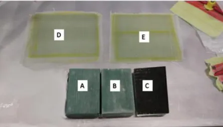
Five specimens were produced:
A. With original characteristics of the hull, used to compare the base structure and the enhanced one;
B. With addition of 2 wt% nano-silica;
C. With addition of 2 wt% nano-silica and a layer of silicon painting. The silicon painting is used to cover the hull protecting it from corrosive environment;
20 Experimental Procedure
E. Monolithic laminate with addition of 2 wt% nano-silica.
The structure and dimensions of specimens A, B and C are illustrated in Figure 3.1. Figure 3.2 depicts the produced specimens.
Figure 3.1 - Specimens structure and dimensions.
Figure 3.2 - Specimens produced by vacuum infusion process
To produce the specimens a plain surface was prior prepared. The superfine cleaning procedure is to apply two times the cleaner with an interval of 10 minutes, then apply the sealer on the same surface. At the borders of the surface paper tape is applied to prevent the inflow of release agent. Next step is to apply release agent to prevent resin sticking to surface. The surface is ready for the vacuum infusion process.
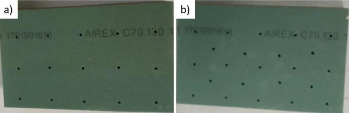
The PVC core is perforated with 2.4 mm diameter holes (Figure 3.3a) to transport the resin from the top to bottom, diffusing it in both sides to the glass fibre. Since resin with nano-silica is more viscous it was necessary to add more holes because of the difficulty to spread the resin equally on top and on bottom and to facilitate the infusion process (Figure 3.3b). The core was then enveloped with glass fibre. Enveloping it from all sides allows to prevent weak spots. Figure 3.4 represents the core enclose procedure and Figure 3.5 illustrates the fibre types.
Experimental Procedure 21 Figure 3.3 - PVC core Airex C70.130, a) original core, b) core with more holles to facilitate infusion
process
Figure 3.4 - Envelope procedure
Figure 3.5 – Fibre types
For the specimens to have better surface finish is necessary to apply peel ply under and above the enveloped core or monolithic. Above the monolithic/core is placed the infusion net, infusion tube and resin injection tube as seen in Figure 3.6. The resin flows through the resin injection tube and is distributed along the composite with the help of infusion tube, spiral net and infusion net. Around the surface, where was applied paper tape, paper tape it removed and applied mastic. At both sides of the monolithic/core impermeable net with spiral vacuum tube inside is placed. Impermeable net is necessary to stop the resin from escaping the vacuum bag. Vacuum bag attached with mastic is
22 Experimental Procedure
placed around the assembly. The vacuum bag needs to have more area then the infusion surface, because the bag needs to enclose all materials placed on the infusion surface.
Figure 3.6 - Vacuum infusion process: 1) Infusion net; 2) Peel ply; 3) Impermeable net with vacuum tube inside; 4) Manometer place; 5) Infusion line with spiral infusion tube; 6) Mastic; 7) Valve; 8) Vacuum tube;
9) Infusion tube.
To verify that the vacuum is achieved is necessary to perform the drop test. Vacuum is applied and when the pressure value is around 20 mbar the vacuum bomb, WAKware CVS 500C, is stopped. The vacuum value will increase. After 10 minutes if the value didn’t increase more than 50 mbar above the initial value, then the vacuum it´s considered achieved. In the drop test the initial value was 21,3 mbar and after 10 minutes the pressure increased to 47,6 mbar. The increase in pressure is 26,3 mbar (Table 3.1) inferior to 50 allowing to proceed to next step.
Table 3.1- Drop test pressure Time [s] Pressure [mbar]
0 21.3 1 22.5 2 25.2 3 27.5 4 30.5 5 33.5 6 36.5 7 40.0 8 42.2 9 44.9 10 47.6
Experimental Procedure 23
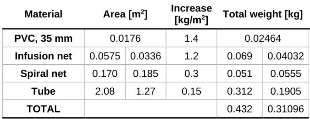
To reduce the waste of the resin is possible to calculate approximately the quantity of the resin necessary. It is necessary to know the area of the fibres, the PVC core, the tubes and extra material used. Table 3.2 and Table 3.3 present the calculus for the estimation of the amount of resin used.
Table 3.2 - Resin in fibres
Material
Area [m
2]
Weight
[kg/m
2]
Nº of
layers
Total weight
[kg]
ETL
0.0649 0.0414
0.600
1
0.03896 0.0248
EBX
0.0649 0.0414
0.600
1
0.03896 0.0248
ETL
0.0649 0.0414
0.800
2
0.10384 0.0662
TOTAL
0.18176 0.1158
Table 3.3 - Resin in PVC and tubes
Material
Area [m
2]
Increase
[kg/m
2]
Total weight [kg]
PVC, 35 mm
0.0176
1.4
0.02464
Infusion net
0.0575 0.0336
1.2
0.069
0.04032
Spiral net
0.170
0.185
0.3
0.051
0.0555
Tube
2.08
1.27
0.15
0.312
0.1905
TOTAL
0.432
0.31096
To produce the 5 specimens the amount of necessary resin was 892 g, 522.9 g on monolithic and 368.9 g on specimens with PVC core. To increase the hardness of the resin and to speed up its hardening process, a proportion of 31 % of hardener was added (276.4 g). In total, 1172 g of mixture, resin and hardener, was used.
Regarding the enhanced specimens (Specimens B, C and E), it was found that to produce 1 monolithic and 1 specimen with PVC core it was needed 690 g of resin. In order to try to increase the resistance to marine environment 2 wt% nano-silica was added to resin, equivalent to 1.38 g of nano-silica.
The resin was placed in the bucket and linked to the infusion tube. After, the vacuum bomb was turned on and the resin was infused into the fibres. When the resin reached the impermeable net the valve of the bucket was closed and after 10 more minutes the vacuum bomb also turned off. As normally, the resin hardened in 24 hours. Then, the GFRP and the monolithic were removed and to improve further the properties of the material, were subjected to 60 ºC for 24 hours.
Specimen C was painted with silicon paint to observe if the silicone coating is an appropriate solution to additional improvement of the marine environment resistance of the material.
24 Experimental Procedure
3.2 Accelerating Aging Chamber
To simulate the marine environment the accelerated aging chamber of UV radiations combined with condensation cycles available in the Mechanical Technology Laboratory of NTI, DEMI was used (Figure 3.7). This equipment was designed, produced and validated in a previous work [20]. In this chamber is possible to control the parameters: UV radiation, humidity percentage, temperature and cycle time. As the chamber needs to be autonomous, is controlled by several sensors, such as temperature, humidity, and water level.
1) UV radiation system
2) Fans to control the temperature inside the chamber
3) Step motor
4) Heating resistance 5) Water level sensor 6) Water container for refill
Figure 3.7 - 3D model of the accelerating aging chamber
The dry phase is represented by UV radiation with high temperature. The necessary UV radiation was provided by a Osram HTC400-241 lamp that radiates UVA with wavelengths between 315-400 nm (82 W) and UVB 280-315 nm (12 W). At noon the max sunlight radiates 0.68 W/m2 at
340 nm [20].
The wet phase is represented by a condensation with high humidity and temperature. The humidity is achieved by heating the water in the container below the specimens. The temperature of the water achieves 80 ºC increasing the humidity in the chamber by condensation. The heating resistance is responsible for heating the water controlling the percentage of humidity in the chamber.
The chamber dimensions were designed to allow aging simultaneously 3 specimens (160x110x42 mm), alternating between wet and dry phase and simulating daytime and nigh time in marine environment. To simulate the real conditions of the hull, a step motor rotates the specimens so that they are immersed and exposed to UV radiation. All the operations and sensors are controlled by Arduino Mega 2560. 1 2 3 4 5 6
Experimental Procedure 25
3.3 Accelerated aging with UV and Humidity
In accordance with ASTM G154-06 [28] for UV fluorescent lamps, the ideal exposure times for each wavelength are as shown in Figure 3.8. The used lamp has a vast UV wavelength radiation, so it became necessary to calculate a new value of exposition time. The chosen time was:
• 4 hours UV radiation at 50 ºC, dry phase; • 2 hours condensation at 40 ºC, wet phase.
Figure 3.8 - Parameters according to ASTM G154-06 [28]
The values from the sensors are collected and written on a SD card. Knowing the collected data helps to know if during the aging process everything goes as planned.
During the dry phase the temperature was controlled to be between 45-50 ºC and humidity 20 % as seen in Figure 3.9. Through the first hour the environment needs to change accordingly to the new parameters.
26 Experimental Procedure
The condensation system is composed by a reservoir with water and a 2 kW resistance. The resistance is responsible for heating the water and consequently increasing the humidity. The temperature is maintained at approximately 30 ºC and the humidity at 95 %, as seen in Figure 3.10. During the first 15 minutes the temperature reduce, with the help of the fans and humidity increase. The humidity increase takes longer to increase because the water needs to heat up first.
Figure 3.10 - Condensation cycle
Figure 3.11 depicts the experimental apparatus for the aging tests.
A. Specimen with the original hull characteristics;
B. Enhanced specimen (2 wt% nano-silica);
C. Enhanced (2 wt% nano-silica) and silicon painted specimen.
Figure 3.11 – Experimental apparatus for the aging tests
The specimens where in chamber for 1000 hours. Figure 3.12 shows the radiation (dry phase) and the humidity (wet phase) cycle for 24 hours. During the 1000 hours, 31 days, there is a sequential change of cycle type, namely radiation and humidity cycle. Through this time is necessary to refill the water in the container.
Experimental Procedure 27 Figure 3.12 - 24 hours Radiation and Humidity cycle
3.4 Three-point Flexural Test
Flexure testing of composites is commonly performed since composite structures are subjected to flexural loading in typical applications. Depending on the span length as well as the material orientation of the specimen during a test, either a tensile, compressive or shear failure might be produced under flexural loading.
For composite specimens, ASTM D 7264 [29] specifies the span-to-thickness ratio, l/t, to be 32:1 for three-point bend test. This test method determines the flexural stiffness and strength properties of polymer matrix composites and corresponds to the standard Procedure A (Figure 3.13). For flexural strength, the standard supports span-to-thickness ratio is chosen such that failure occurs at the outer surface of the specimens, due only to the bending moment.
Figure 3.13 – Loading diagram for three-point flexural test [29]
The three-point bending flexural test provides data for Maximum Flexural Stress, Flexural Strength, Maximum Strain, Stress at Strain, Flexural Secant and Flexural Chord Modulus of Elasticity and Failure Mode and Location.
![Table 2.1 - Advantages and disadvantages of most used resins [5]](https://thumb-eu.123doks.com/thumbv2/123dok_br/18149975.871884/25.892.129.784.456.812/table-advantages-disadvantages-used-resins.webp)
![Figure 2.2 - Schematic of composite reinforced with: a) short fibres oriented preferentially; b) randomly oriented [5]](https://thumb-eu.123doks.com/thumbv2/123dok_br/18149975.871884/26.892.279.624.626.800/figure-schematic-composite-reinforced-oriented-preferentially-randomly-oriented.webp)
![Figure 2.3 - Schematic representation of structural composites. a) laminated; b) sandwich panels [5]](https://thumb-eu.123doks.com/thumbv2/123dok_br/18149975.871884/27.892.256.646.334.621/figure-schematic-representation-structural-composites-laminated-sandwich-panels.webp)
![Table 2.3 - Comparative Data for Some Core Materials [7]](https://thumb-eu.123doks.com/thumbv2/123dok_br/18149975.871884/29.892.159.773.126.304/table-comparative-data-for-some-core-materials.webp)
![Figure 2.6 - Spray Lay-up illustration process [8]](https://thumb-eu.123doks.com/thumbv2/123dok_br/18149975.871884/31.892.248.666.101.365/figure-spray-lay-up-illustration-process.webp)
![Figure 2.7 - Vacuum Bagging process [9]](https://thumb-eu.123doks.com/thumbv2/123dok_br/18149975.871884/32.892.156.708.174.353/figure-vacuum-bagging-process.webp)