UNIVERSIDADE DA BEIRA INTERIOR
Engenharia
Substitution of a conventional Gas Turbine by a
HT-PEMFC APU
Feasibility Study
(Versão revista após discussão)
Bruna Carolina Castro Pereira Araújo
Dissertação para obtenção do Grau de Mestre em
Engenharia Aeronáutica
(ciclo de estudos integrados)
Orientador: Prof. Doutor Francisco Miguel Ribeiro Proença Brójo
”We cannot solve a crisis without treating it as a crisis…if solutions within the system are so impossible to find, then… we should change the system itself.”
Acknowledgments
I would first like to express my sincere gratitude to my advisor, Professor Francisco Brójo, who guided me and was always patiently willing to help me. His office was always open whenever I ran into a trouble spot or had a question about my research or writing. He consistently allowed this work to be my own work but steered me in the right direction whenever I needed it.
I would also like to thank my colleagues at Universidade da Beira Interior, for their amazing support and friendship. Ana, André, António, Cátia, Coelho, Daniel, Francisco, Ginja, Gonçalo, Inês, Nídia, Nuno, Maria, Oliveira, Paulo, Rodolfo, Rocha and Mister Romeiro. I could never thank you enough for all this journey we spent together.
In addition, I would like to thank my family, especially my parents and my brother for their invaluable efforts and trust. You are always there for me. And for everything you have done, there are no words to express my gratitude and love towards you.
I would also like to thank my boyfriend for the incredible support, patience, and help at all times. Finally, there are my friends, who were incredible and indispensable during this journey. Ana, Andreia, Beatriz Coelho, Beatriz Silva, Dévora, Jó, João, Joana, Liliana, Luís, Maria, Rita, Rui and Sofia. Thank you for helping me stay focused and for being a happy distraction when I needed one.
Resumo
Uma Unidade Auxiliar de Energia (APU) é um sistema bastante utilizado na produção de energia elétrica em aeronaves. Alcançar melhorias na economia de combustível desses veículos depende diretamente do tipo e do ponto de operação da APU. Essas melhorias devem estar focadas não só na redução dos custos de operação e manutenção, mas também na redução ou até mesmo eliminação de emissões e ruídos. A evolução de uma APU é, portanto, uma questão importante para todos aqueles que direta ou indiretamente estão associados a um aeroporto.
Este trabalho aborda um sistema APU de uma célula de combustível de membrana polimérica de troca protónica de alta temperatura (HT-PEMFC) usado como caso de estudo e sugerido como uma alternativa mais sustentável para o Airbus A320. Por conseguinte, existem três objetivos principais para este tra-balho, onde o estudo e a implementação de medidas operacionais de uma ferramenta de software através do MATLAB é a chave para realizá-las.
O primeiro objetivo é analisar vários parâmetros de um HT-PEMFC, a fim de prever o comportamento da célula. Além disso, uma vez que a operação da pilha depende do combustível fornecido ao sistema, que neste caso é o metano, e que este não pode ser diretamente alimentado ao HT-PEMFC, é necessário o processamento do combustível. Para isso é feita uma Reforma de Metano a Vapor e uma Reação de Deslocamento de Água a fim de produzir um gás rico em hidrogénio e com uma baixa percentagem de monóxido de carbono. A máxima potência de saída deste sistema fornecido com metano é estimado em 250 kW para uma temperatura de operação da célula de 180℃ e sob uma pressão de 1.5 atm. As eficiências globais de energia e exergia alcançadas para este sistema são de 41.29 % e 39.95 %, respetivamente. O segundo objetivo é realizar a análise termodinâmica do sistema HT-PEMFC APU baseada na primeira e segunda leis da termodinâmica. As equações de balanço de massa, energia, entropia e exergia são escritas e aplicadas ao sistema e a cada um dos seus componentes. As irreversibilidades ocorridas nas diferentes unidades do sistema integrado são investigadas através da análise de exergia destruída nessa unidade. Deste modo, as unidades com maior destruição exergética estão associadas às reações químicas que nelas sucedem.
O último objetivo tem como função encontrar o ponto de equilíbrio entre o aumento de peso do sistema proposto (HT-PEMFC APU) e o combustível economizado devido à sua maior eficiência. Visa ainda com-parar as emissões de gases de escape entre os dois sistemas, para um mesmo voo realizado por um Airbus A320 entre Porto e Frankfurt.
Finalmente, os resultados desta pesquisa são muito encorajadores, e mesmo que o seu potencial de econo-mia seja improvável de ser alcançado num cenário real devido à natureza e imprevisibilidade do tráfego aéreo, é uma solução atraente para países que enfrentam uma legislação cada vez mais forte e, deste modo, garantir um ar mais limpo e um futuro mais sustentável.
Palavras-chave
APU, HT-PEMFC, Célula de Combustível, Reforma a Vapor, Reacção de Deslocamento da Água, Balanços Termodinâmica, Energia, Exergia, Emissões, Pesos Preliminares
Abstract
An Auxiliary Power Unit (APU) is a system widely used for electric power generation in aircraft. The improvements in fuel economy and emissions of these vehicles directly depend on the type and operat-ing point of the APU. These improvements should not only concern reducoperat-ing operatoperat-ing and maintenance costs, but also emissions and noise. Improving an APU is, therefore, an important issue for all those di-rectly or indidi-rectly associated with an airport.
This work deals with a High-Temperature Proton Exchange Membrane Fuel Cell (HT-PEMFC) APU system used as a case study and suggested as a more sustainable alternative for the Airbus A320. Consequently, there are three main goals for this work, where the study and implementation of operational measures in a software tool using MATLAB is the key to accomplishing them.
The first objective is to analyze several parameters of a HT-PEMFC, in order to predict the behavior of the fuel cell as a stack. In addition, since the operation of the stack depends on the fuel supplied to the system, which in this case is methane, and that methane cannot be directly fed to the HT-PEMFC, a previ-ous fuel process is necessary. Therefore, Methane Steam Reforming and Water Gas Shifting processes are implemented to produce a hydrogen-rich gas with a low percentage of carbon monoxide. The maximum output power of this methane-supplied system is estimated at 250 kW for an operating temperature of 180ºC under 1.5 atm of pressure. The overall energy and exergy efficiencies achieved for this system are 41.29 % and 39.95 %, respectively.
The second objective is to perform the thermodynamic analysis of HT-PEMFC APU based on the first and second laws of thermodynamics. The mass, energy, entropy, and exergy balance equations are writ-ten and applied to the system and its components. The irreversibilities occurring in different devices of the integrated system are investigated through the exergy destruction analysis in those units. The units with the most significant exergy destruction are associated with the chemical reactions that occur in them. The ultimate goal is to find the breakeven weight between the additional weight of the HT-PEMF proposed system and the fuel saved due to higher efficiency of the system. Moreover, it compares the emissions of the conventional APU and the HT-PEMFC systems, during a flight from Porto to Frankfurt carried out by an Airbus A320.
Finally, the results of this research are very encouraging, and even though its fuel consumption saving potential is unlikely to be achieved in a real-world scenario due to the nature and unpredictability of air traffic, it is an attractive solution for countries facing ever stronger legislation to ensure cleaner air and a more sustainable future.
Keywords
APU, HT-PEMFC, Fuel Cell, Steam Reforming, Water Gas Shifting, Thermodynamic Balances, Energy, Exergy, Emissions, Preliminary Weights.
Contents
1 Introduction 1 1.1 Motivation . . . 1 1.2 Objectives . . . 2 1.3 Dissertation Outline . . . 2 2 Literature Review 5 2.1 History of the APU . . . 52.2 Auxiliary Power Unit . . . 6
2.3 Types of APU . . . 7
2.3.1 Gas Turbine APU . . . 7
2.3.2 Energy Recovery APU . . . 9
2.3.3 Batteries . . . 10
2.3.4 Air Bottle . . . 11
2.3.5 Free-Piston Linear Generator . . . 11
2.3.6 Fuel Cell Stack . . . 12
2.4 Advantages and Disadvantages of the different types of APU . . . 16
2.5 Considered parameters for aeronautical application . . . 17
2.5.1 Fuel and Oxidant supply . . . 17
2.5.2 Altitude Sensitivity . . . 18
2.6 Energy and Exergy Analysis . . . 19
2.6.1 Thermodynamic Balances . . . 20
2.6.2 System Efficiency . . . 21
2.6.3 Efficiency of Fuel Cells Applied in Aircraft . . . 22
3 Case Study 23 3.1 Aircraft and APU considered . . . 23
3.1.1 Weights of APU Integration . . . 24
3.1.2 Emissions and Fuel Consumption . . . 24
3.2 HT-PEMFC APU System . . . 25
3.2.1 Assumptions, Limitations and Delimitations . . . 26
3.2.2 System Configuration . . . 27
3.2.3 Configuration of Stack for Desired Load Condition . . . 28
4 Methodology 31 4.1 Determination of Thermodynamic Properties . . . 31
4.1.1 Enthalpy and Entropy for Gaseous Currents . . . 31
4.1.2 Physical Exergy and Chemical Exergy . . . 32
4.1.3 Energy, Entropy and Exergy Rates . . . 32
4.2 HT-PEMFC Integrated System with Onboard Hydrogen Production . . . 33
4.2.1 Fuel Processor Mathematical Model . . . 33
4.2.2 Fuel Cell Mathematical Model . . . 34
4.2.3 Efficiency of HT-PEMFC Integrated System . . . 40
4.3 Auxiliary Units . . . 41
4.3.2 Fuel Compressor . . . 42 4.3.3 Pump . . . 42 4.3.4 Combustion Chamber . . . 43 4.3.5 Gas Turbine . . . 44 4.3.6 Heat Exchangers . . . 44 4.4 Thermodynamic Balances . . . 45 4.4.1 Air Compressor . . . 45 4.4.2 Fuel Compressor . . . 46 4.4.3 Pump . . . 46 4.4.4 Steam Reformer . . . 47
4.4.5 Water Gas Shifting . . . 48
4.4.6 HT-PEMFC . . . 49
4.4.7 Combustion Chamber . . . 49
4.4.8 Gas Turbine . . . 50
4.4.9 Heat Exchangers . . . 51
4.4.10 Heat Recovery Steam Generator . . . 53
4.5 Overall System . . . 54
4.5.1 Entropy Generation and Exergy Destruction . . . 54
4.6 Overall System efficiency . . . 55
4.7 Numerical solution . . . 56
5 Results and Discussion 59 5.1 Development of Algorithm for Predicting Stack Performance . . . 59
5.1.1 Fuel Concentration as Functions of Reformer and Shifting Parameters . . . 59
5.1.2 Effect of Pressure and Temperature on Cell Performance . . . 60
5.1.3 Effects of CO Concentration on Cell Performance . . . 62
5.1.4 Voltage Losses . . . 64
5.1.5 Model Validation . . . 64
5.1.6 Design Operating Point . . . 66
5.2 Thermodynamic analysis . . . 67
5.3 Preliminary Weight Estimates . . . 72
5.3.1 Air Compressor . . . 72
5.3.2 Fuel Pump . . . 73
5.3.3 Water pump . . . 73
5.3.4 Heat Exchangers . . . 74
5.3.5 Fuel processor . . . 74
5.3.6 Fuel Cell Stack . . . 75
5.3.7 DC/DC Converter . . . 75
5.3.8 Combustion Chamber . . . 76
5.3.9 Fuel Tank . . . 76
5.3.10 Water Tank . . . 76
5.4 Integration of the HT-PEMFC into the Airbus A320 . . . 77
5.4.1 Fuel Savings due to Efficiency . . . 77
5.4.2 Impact of HT-PEMFC APU Weight on Aircraft Fuel Consumption . . . 78
5.4.3 Break-even Weight . . . 79
6 Conclusions 81
6.1 Future Works . . . 82
Bibliography 83
A Annexes 89
List of Figures
2.1 Supermarine PB31E Nighthawk with an auxiliary power unit installed aft of the main engine. 5
2.2 Turbojet Junker Jumo 004 started with a Riedel APU. . . 6
2.3 Maintenance of an APU onboard of a A320. . . 6
2.4 Distribution of energy for the airplane and its power consumption. . . 7
2.5 Types of APUs for aircraft application . . . 8
2.6 Typical gas turbine APU using the Brayton cycle. . . 8
2.7 A proposed energy recovery APU. . . 10
2.8 Batteries APU system for Boeing 787. . . 10
2.9 Aircraft pneumatic brake system. . . 11
2.10 Toyota Central RD developing free piston engine linear generator. . . 12
2.11 Basic schematic of a unit cell. . . 13
2.12 Boeing Phantom Works. . . 14
2.13 Antares DLR-H2 platform . . . 15
2.14 SOFC-GT APU implemented at the tail end of an aircraft. . . 16
2.15 Evaluation of system efficiency for various hydrogen supply and oxidant supply concepts under cruise operation conditions. . . 18
3.1 Diagram of the alternative APU feasibility evaluation. . . 23
3.2 Electric distribution systems for traditional aircraft such as A320 and B737. . . 24
3.3 Total electrical load on an A320 engine generators during major segments of flight. . . 25
3.4 Proposed scheme for system layout . . . 26
3.5 HRSG flow arrangement. . . 28
4.1 Schematic diagram of a HT-PEMFC and the catalyst layer using the thin electrolyte film assumption. . . 35
4.2 Air Compressor control volume . . . 45
4.3 Fuel Compressor control volume . . . 46
4.4 Pump control volume . . . 47
4.5 Steam reformer control volume . . . 47
4.6 Water Gas Sifting control volume . . . 48
4.7 Fuel cell control volume . . . 49
4.8 Combustion Chamber control volume . . . 50
4.9 Gas turbine control volume . . . 50
4.10 HX-1 control volume . . . 51
4.11 HX-2 control volume . . . 51
4.12 HX-3 control volume . . . 52
4.13 HX-4 control volume . . . 53
4.14 Heat Recovering Steam Generator control volume . . . 53
4.15 Overall system control volume . . . 54
4.16 Workflow of the created MATLAB program. . . 57
5.1 Cell performance at constant temperature of 150ºC and at pressures of 1, 1.5, 2, 2.5 and 3 atm. . . 61 5.2 Cell efficiency at constant temperature of 150ºC and at pressures of 1, 1.5, 2, 2.5 and 3 atm. 61
5.3 Fuel cell voltage at temperatures of 150, 160, 170 and 180ºC. . . 62
5.4 Fuel cell performance at temperatures of 150, 160, 170 and 180ºC. . . 62
5.5 Analyzing power density with temperature of 150 ºC, 160 ºC, 170 ºC and 180 ºC. . . 63
5.6 Polarization curve with 1%, 2%, 5% and 10% of CO at 160 ºC and 1 atm. . . 63
5.7 CO concentration of 0%, 2% and 5% of CO for temperatures of 160 ºC and 180 ºC. . . 64
5.8 Activation polarization at anode, activation polarization at cathode and ohmic losses at 160 ºC. . . 65
5.9 Validation of the voltage characteristics of the HT-PEMFC cell for 0%, 5% and 10% CO concentration with experimental results. . . 65
5.10 Comparison of the experimental and numerical dry reformate gas from the fuel processor. 66 5.11 Polarization curve and power density curve at 180 ºC and 1.5 atm. . . 66
5.12 P400-PRO Turbine Engine. . . 73
5.13 MZR-7205 micro-annular gear pump. . . 73
5.14 2282-M05X12 water pump. . . 74
5.15 MGV600T11K7 DC/DC converter. . . 76
5.16 Weishaupt Olbrenner WL5 PB-H purflam. . . 76
5.17 Molar compositions of exhaust gases from the combustion chamber. . . 77
5.18 Weight percentage of every system unit. . . 79
5.19 Plot comparing the estimated system weight in scoping calculation to the breakeven weight for 1.5 atm, 0.56 V/cell. . . 80
List of Tables
2.1 Comparison of the different APUs mentioned in this work. . . 17
2.2 Hydrogen production costs in euros of 1990 . . . 18
2.3 Volume percentage composition of products from different processes for producing hydrogen-rich feed for fuel cells. . . 19
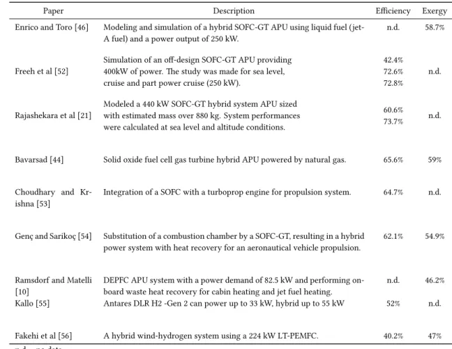
2.4 System description, energy and exergy efficiency of fuel cells used as an APU/propulsion application. . . 22
3.1 Airbus A320 and Honeywell 131-9A specifications. . . 24
3.2 APU emissions and fuel consumption. . . 25
3.3 Description, temperature, pressure and mole fraction of each stream represented in Figure 3.4. . . 29
5.1 Parameters used in the simulation of HT-PEMFC stack. . . 60
5.2 Hydrogen and carbon monoxide fractions in the synthesis gas obtained from the steam reforming process. . . 60
5.3 Analyzing the performance of the fuel processor by varying the pressure parameter. . . 61
5.4 Input parameters and results obtained for the fuel processor. . . 67
5.5 Input parameters and results obtained for fuel cell stack. . . 67
5.6 Molar compositions of gaseous streams. . . 68
5.7 Thermodynamic properties of every stream. . . 69
5.8 Heat transfer rates to the environment in some system units. . . 70
5.9 Input, output, and entropy generation rates in every system unit. . . 70
5.10 Input, output, loss, and exergy destruction rates associated with system units. . . 71
5.11 Exergy efficiency and exergy destruction quotient of the subsystems and the global system. 72 5.12 Base case simulation results of the overall system. . . 72
5.13 HT-PEMFC cruise full power system results. . . 75
5.14 Mass of every HT-PEMFC APU component considered in this system analysis. . . 78
5.15 Mass Rate of Fuel Savings for Electrical Generation. Does not include effect of HT-PEMFC mass. . . 78
Acronyms List
AC Alternating Current AEA All Electric Aircraft APU Auxiliary Power Unit
ATRA Advanced Technology Research Aircraft
CC Combustor Chamber
DC Direct Current
DEPFC Direct Ethanol Polymer Fuel Cell ETOPS Extended Twin Operations
FC Fuel Cell
FT Fischer-Tropsch
GT Gas Turbine
HT-PEMFC High Temperature Proton Exchange Membrane Fuel Cell HRSG Heat Recovery Steam Generator
HX Heat exchanger
ICAO International Civil Aviation Organization ISA International Standard Atmosphere
LT-PEMFC Low Temperature Proton Exchange Membrane Fuel Cell MEA More Electric Aircraft
ORC Organic Rankine Cycle PEM Polymer Electrolyte Membrane
PEMFC Polymer Electrolyte Membrane Fuel Cell SOFC Solid Oxide Fuel Cell
SOFC-GT Solid Oxide Fuel Cell - Gas Turbine
SR Steam Reformer
MSR Methane Steam Reforming UAV Unmanned Aerial Vehicle WGS Water Gas Shifting
Nomenclature
aH2O Water activity
Acell Active surface area of the cell, m2
cp Specific heat capacity at constant pressure, J mol−1K−1
Ci Specie i concentration
C0
i Reference standard concentration of specie i, mol cm−1atm−3
Ci,P t Specie i concentration in the thin film at platinum-electrolyte boundary, mol cm3
Cdissolve Hydrogen and oxygen concentration in the thin film at gas pore-electrolyte boundary, mol cm3
Di Diffusion coefficient of specie i
DP A Diffusion through ionomer, cm2s−1
Dijef f Effective binary diffusion, cm2s−1 ex Specific exergy, kW kmol−1
exch Chemical exergy, J mol−1
ex0ch Standard chemical exergy, kW kmol−1 exph Physical exergy, J mol−1
E0 Ideal cell voltage at standard conditions, V
Erev Nernst potential, V
Eact Activation energy, J mol−1
˙
Ex Exergy, kW
˙
Exdest Exergy destruction rate, kW
F Faraday constant, 96 485 C mol−1
g Gravitational acceleration, 9.81 m2s−1
G0 Gibbs potential, J mol−1 h Specific enthalpy, J kmol−1
h0
i Enthalpy at standard conditions, J kmol−1K−1
h0f Standard enthalpy of formation, kJ kmol−1
H Henry’s constant for the given species solubility in the electrolyte, m3atm mol−1 i Current density, A m−2
i0 Exchange current density, A m−2
iCO
0 Exchange current density for hydrogen oxidation after CO poisoning
iref0 Exchange current density at reference temperature, A cm−3
˙
I Irreversibility, kW
I Current, A
Icell Cell current, A
Istack Stack current, A
Keq Equilibrium constant
lm Membrane thickness, m
LHV Lower Heating Value, J mol−1
L/D Lift to drag ratio
Lc Catalyst loading, weight of platinum per unit area, mg cm−2
m Mass, g
˙
m Mass flow rate, kg s−1
M Molecular weight, g mol−1
n Mole number, mol
Nc Number of cells
Nmod Number of modules
pp Partial pressure, Pa
P Pressure, Pa
P0 Environmental dead state pressure, Pa
Pan Pressure at anode, Pa
Pc Gas critical pressure, Pa
Pca Pressure at cathode, Pa
Pf c Fuel cell pressure, W
Pref Reference pressure, Pa
Ptot Pressure of the flow at the reformer, Pa
p∗H
2O Saturation vapor pressure of pure water at given temperature, atm
˙
Q Heat transfer rate, W
R Universal gas constant, 8.3145 J mol−1K−1
RH Relative humidity, %
s Specific entropy, J mol−1K−1
s0
i Entropy at standard conditions, J kmol−1K−1
sfc Specific fuel consumption, mg N−1s−1
˙
Sgen Entropy generation rate, W K−1
SP t Surface area of platinum (Pt) per geometric electrode area,
t Time, s
tGDL Gas diffusion layer thickness, m
T Temperature, K
T0 Environmental dead state temperature, K
Tc Gas critical temperature, K
Tp Saturation temperature, K
Tref Reference temperature, K
Ua Air utilization ratio
Uf Fuel utilization ratio
Vact,an Activation losses at anode, V
Vact,ca Activation losses at cathode, V
Vohm Ohmic resistance, V
Vcell Output cell voltage, V
˙
W Power, W
˙
WAP U APU electrical power output, W
˙
Wcomp,a Air compressor power, W
˙
Wcomp,f Fuel compressor power, W
˙
Wf c Fuel cell stack electrical power output, W
˙ Wp Pump power, W ˙ Wt Turbine power, W X Mole fraction z Number of electrons
Greek symbols
α Charge transfer coefficient
β Electro-osmotic drag coefficient of water δ Component thickness, m
∆¯h Enthalpy change, J kmol−1
∆G Standard Gibbs free energy of a reaction, kJ ∆H0 Standard enthalpy change, J mol−1
∆P Boost in pressure of liquid water, Pa ∆S0 Standard entropy change, J mol−1K−1
η Energy efficiency γ Ratio of specific heats
κ Reaction order
σ Conductivity, S cm−1 λ Fuel to air ratio ψ Exergy efficiency
τ Tortuosity
θCO Fraction of catalyst surface covered by CO
ε Porosity, %
υ Specific volume, m3kg−1
φ Air stoichimetry
Subscripts
a Air act Activation an Anode c Critic ca Cathode cog Cogeneration comp Compressor cc Combustion chamber dest Destruction ele Electrical eg Exhaust gases f Fuel fc Fuel cell fp Fuel processor F Flight gen Generation i Stream j Specie ohm Ohmic r Reformer ref Reference rev Reversible sat Saturation st Steam t Turbine th Thermal w Water shiftingChapter 1
Introduction
1.1 Motivation
Since dawn of mankind, energy is the matter that drives evolution. Energy is the origin of a major tech-nological progress and its increasing people’s quality of life, but at what price?
The world has witnessed a frightful energy condition. Frightful because traditional resources are coming to an end, and its massive exploitation is sideways with our health, our economy and our environment. For the last two centuries, the world energy condition to rely on obsolete energy, more precisely, fossil fuels is literally being fatal. These non-renewable energies are accountable for irreversible environmental damage, causing many diseases and the dreadful wars in their profit.
After the Industrial Revolution and especially after World War II, enormous amounts of carbon dioxide were released to the atmosphere, from industrial activity. Since the beginning of industrialization, 200 years ago, the planet suffered the fastest environmental changes in the history of the Earth.
Nonetheless, carbon dioxide is one of the most important gases in our atmosphere and is one of the green-house effects responsible for making this planet habitable. The problem starts when the emissions are in colossal scale and increase the planet capacity to absorb the infrared radiation, influencing its natural bal-ance of energy.
The consequences of relying on fossil fuels are starting to be notable at plain sight, where glacial melting is an example. As the reason for that, it is important to understand what activities are in the origin of these emissions to study different ways to improve or even replace it for zero-emissions technology. Nowadays, the outcome polution of the transport sector is one of the major responsible accounting for 14% of greenhouse emissions, where 3% is coming from the aviation industry [1, 2]. From those 3 %, the airport ground-based emissions coming from Auxiliary Power Unit (APU) holds 20% [3].
APU is an auxiliary power unit used in most commercial aircraft, some private jets and helicopters which the main purpose is to provide electrical, pneumatic and hydraulic power to the aircraft. Nevertheless, APU is the cause of 50% of the aircraft maintenance costs, 12% of delays and more than 5% of the daily fuel consumption [1, 3, 4].
The degradation of quality of life by the increasing number of airplanes and routes on the aviation indus-try is not only provided from air pollution, the hazards of noise pollution and how it influences human physical and psychological health have to be considered.
Aware of this increasing problem that was compromising the planet, the United Nations Organization de-fended that a more restricted environmental and energetic policy to control the greenhouse gas emissions was required, which was proposed in 1997 to most of the industrialized countries, designated Kyoto’s Protocol1, and more recently the Paris Agreement was approved in 2015.
However, the challenge is urgent when the safety of the planet is at risk, and the need to replace fossil energy for cleaner ones is inevitable [5]. Renewable energies can play a driving role in overcoming the threats of decline and collapse.
The solution goes through finding new lasting and non-polluting energy sources able to respond or even overcome today’s needs. Accordingly, these concerns led to a tremendous progress in the efforts to move
1Ratification by at least 55 states to the Convention, effective from February 12th2005 to December 31st2012.
towards more electric aircraft (MEA) or even all electric aircraft (AEA). A renewable energy system will result in a zero emission, noise reduction flight using an AEA, and once adapted in large scale could reduce the aviation sector percentage on greenhouse emissions. In this regard, the base of this work is studying the replacement of the conventional APU for a more rationally-efficient component.
Fuel cells show high potential with outstanding efficiency and clean energy [6]. For that reason, herein a promising alternative to the current APU is presented. Fuel cells can serve as an emergency power source and continuously produce electrical energy to supply an entire flight [7, 8]. This renewable energy system, usually fueled by hydrogen, is being applied to cars and trucks, and the aeronautical industry is already making progress in this area.
There are two types of fuel cells that stand out for aeronautical application: low-temperature proton exchange membrane fuel cell (LT-PEMFC) and high-temperature solid oxide fuel cell (SOFC) [9]. More recently, a direct ethanol polymer fuel cell (DEPFC) for APU application was tested [10].
The APU technology studied in this work is a high-temperature proton exchange membrane fuel cell (HT-PEMFC) with the purpose of a more sustainable aircraft.
In this brief reflection, renewable energies compromise a world of unending opportunities which can be looked with enthusiasm and hope. The opportunity to live in a safer world goes through the study and implementation of these sustainable energies capable of establishing a symbiotic relationship between technology and the environment. In this study, the potential of exergy analysis for the environment and sustainable development implications are reviewed.
1.2 Objectives
In general, the objective of the present work is to verify the feasibility of replacing the conventional gas turbine by a high-temperature proton exchange membrane fuel cell APU. A process of hydrogen energy recovery qualified to provide auxiliary power to the aircraft on the ground and during flight. More specifically, the goals are:
- Understand fuel processing of natural gas into hydrogen and its conversion into electric energy through a fuel cell;
- Build a mathematical model for a high-temperature proton exchange fuel cell using reformed fuel; - Study the system using the first and second law of thermodynamics (energetic and exergetic
anal-yses);
- Identify and evaluate the irreversibilities within the process; - Estimate the weight of the HT-PEMFC APU;
- Determine the system global performance.
1.3 Dissertation Outline
This dissertation is structured into six chapters. The first and current chapter consists of a brief presenta-tion and organizapresenta-tion of the topic. Furthermore, the major reasons for the development of this work and its importance for the future are assigned .
Chapter 2 consists of a literature review on the major topics addressed through this dissertation. A de-tailed APU introduction is followed by the methodology and approach used.
The case study of this work is presented in Chapter 3. There is a presentation of the overall system pro-posed and the validation of that system.
In Chapter 4, a mathematical model for fuel processor and fuel cell are described. Additionally, some important tools used in the model validation are introduced.
In Chapter 5, results are interpreted and explained. Also, the viability of the system is analyzed and dis-cussed.
This dissertation is concluded in Chapter 6, where a global analysis, difficulties and conclusion are dis-cussed as well as the suggestion of identified future topics for future work opportunities.
Chapter 2
Literature Review
In this chapter, the history of the auxiliary power unit and its general concept are introduced. The different types of APUs already in activity or under research are presented and described.
A more detailed review of the concepts of fuel cell-based APU and its main design considerations are explained. In addition, the concepts of energy and exergy, along with their importance for this work, are introduced.
Finally, the thermodynamic model for the validation of the system is described. This part will be the basis for the methodology developed.
2.1 History of the APU
During World War I, the first auxiliary engine was used on the British Coastal class blimp. In a time where radio proved indispensable to communication with another recent development, airplanes, the APU supplied the power for radio transmissions, and in case of an emergency, could power an auxiliary air blower. One of the first records of a military fixed-wing aircraft to have an APU in its design was the Supermarine Nighthawk (see Figure 2.1), an anti-Zeppelin Night fighter whose function was to power a searchlight.
Figure 2.1: Supermarine PB31E Nighthawk with an auxiliary power unit installed aft of the main engine [11]. Later, during World War II, the first operational jet engine was built, the Junker Jumo 004 (see Figure 2.2a). Its operation depended on a starter system, which was designed by the German engineer Norbert Riedel. One of the models developed by Riedel operated as a manual pull-handle to start the piston engine, which in turn rotated the compressor. The system consisted of a 7.5 kW two-stroke flat engine considered as the pioneering example of a mechanical auxiliary power unit to start the main engine and was built into the nose-cone of the turbojet as presented in Figure 2.2b [12].
Meanwhile, US military aircraft were also being equipped with APUs, typically known as putt-putts, even in official training documents. The putt-putt on the Boeing B-29 Superfortress bomber was fitted in the unpressurized section at the rear of the aircraft. Various models of four-stroke, Flat-twin or V-twin engines were used. The putt-putt provided power for starting the main engines and was used after take-off to a
(a) Junker Jumo 004 - the first axial-flow turbojet. (b) Riedel APU used to start the Junker Jumo 004. Figure 2.2: Turbojet Junker Jumo 004 started with a a Riedel APU [13].
height of 3,000 m, and restarted when the B-29 was descending to land [12].
In 1963, the Boeing 727 was the first commercial aircraft to have an operating gas turbine APU providing electrical energy, legally allowed at smaller airports.
Nowadays, APUs are powering regional, executive, commercial and military airplanes including both fixed wing and rotary wing.
2.2 Auxiliary Power Unit
The auxliary power unit or APU is a self-contained unit responsible for providing electrical, pneumatic and hydraulic power to the aircraft, on the ground and during flight. These forms of power can be di-rectly provided or converted using additional onboard equipment - e.g. valves for hydraulic energy [14, 15].Generally located at the rear of the aircraft due to its void space and the need for an opening to expel the exhaust gases [14, 16]. The APU relies on ambient air and fuel from the engines to produce compressed air and electricity. The air intake for the APU is located underneath the tail cone as shown in Figure 2.3, and the opening is controlled by an electrical flap which allows external air to reach the compressor inlet. The fuel is provided from fuel tanks and is the same fuel used for main engines. The APU requires an integral independent oil system for lubrication and cooling [15].
An APU is an engine for functions other than propulsion. Actually, the purpose of an APU is to make the
Figure 2.3: Maintenance of an APU onboard of a A320 [17].
airplane self sustainable on the ground and providing the additional source of power during flight. Fig-ure 2.4 shows the different applications of power required for the aircraft operation and presents detailed
information on their power consumption.
Figure 2.4: Distribution of energy for the airplane and its power consumption [6].
During ground operations, the APU supports the electric and pneumatic systems even before the main engines start. This way saves fuel since the engines are only turned on for take-off time. Furthermore, it supplies bleed air for starting the engines and air conditioning system. During take-off still supplies bleed air for air conditioning, thus avoiding a reduction in engine thrust caused by the use of engine bleed air for this purpose when optimum aircraft performance is required. Is responsible for backing up the elec-trical and pneumatic systems in flight and can be used in emergency situations, such as engine failure. In that case, APU has to assure the operation of electrical power for the avionics and the hydraulic power to control the control surfaces [14].
Accordingly to literature, the APU is a fundamental system for flights with two-engine aircraft and long routes over water or terrain without an alternative airport - Extended Twin Operations (ETOPS) flights. Moreover, if the aircraft safety architecture depends on an available APU is indispensable to have one [15].
2.3 Types of APU
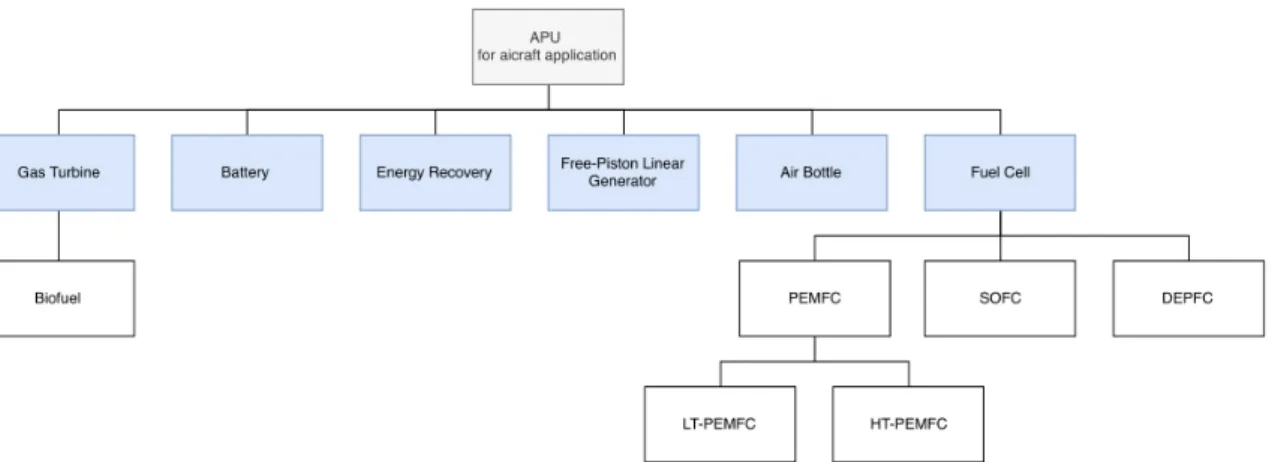
Figure 2.5 highlights APUs already in use or under research with an aeronautical application in view.
2.3.1 Gas Turbine APU
A gas turbine is the conventional APU used in airplanes, favorable for its high power-to-weight ratio [18]. The base design is a single-shaft gas turbine, powering an electrical generator and an air compres-sor, operating accordingly with the Brayton thermodynamic cycle. As demonstrated in Figure 2.6b the Temperature-entropy (T-s) diagram of the Brayton cycle starts with inlet air (0-2) being compressed (2-3) to increase its pressure and temperature, afterward fuel is injected and mixed with hot air for combustion (3-4). Finally, the exhaust gases pass through the turbine (4-5) and are exhausted through the nozzle (5-8) [18].
The gas turbine APU can be divided into three main sections, as presented in Figure 2.6a: - The power section is a turbine engine and produces all the power for the APU;
Figure 2.5: Types of APUs for aircraft application
- The load compressor is responsible for supplying all the pneumatic pressure to the aircraft; - The gearbox transfers the APU power to an electric generator that in turn supplies electricity to the
airplane.
The power source of an APU is generally a battery or a hydraulic accumulator [14].
(a) Gas Turbine APU sections [15]. (b) T-s diagram of Brayton Cycle [19]. Figure 2.6: Typical gas turbine APU (on the left) using the Brayton cycle (on the right).
The design of the gas turbine APU has hardly changed over time, keeping the concept of single cycle gas turbine and reliable technology. The technological reliability is a strong feature when it comes to costs and compatibility with existing aircraft architectures [15]. In contrast, presents relatively low efficiency (30-40% in flight and less than 20% on the ground), high noise and environmental pollution and requires high maintenance support [20, 21]. Nevertheless, it is important to note that APU manufacturers are making efforts towards increasing fuel savings and the life cycle of the APU while decreasing its maintenance. Environmental regulations on air quality and vehicle exhaust emissions and noise are placing severe re-strictions in the aviation sector. In fact, International Civil Aviation Organization (ICAO) has developed Strategic Objective C, Environmental Protection. ICAO proposition aims to minimize the adverse effects of global civil aviation on the environment, which can be attained by developing, adopting, and promoting new or amended measures to:
- Limit or reduce the number of people affected by significant aircraft noise. - Limit or reduce the impact of aviation emissions on local air quality.
The growing demand for air transport results in the need to operate with new technologies, such as the use of sustainable energy for auxiliary power generation. This will reduce fuel consumption and emissions from air and land operations while investing in newer and more eco-efficient aircraft.
2.3.1.1 Biofuel auxiliary power unit
An increase on airport operations results in the need to reduce emissions to control air quality within and around airports. One way to minimize the problem is by developing more environmentally friendly fuels, to reduce dependence on petroleum and consequently emissions.
Gasification is the thermochemical conversion of organic material into a valuable gaseous product, called syngas, and a solid product called char. The biomass gasification (BG) represents an efficient process for the production of second-generation biofuels. The Fischer-Tropsch (FT) process is a combination of chemical reactions that convert a mixture of carbon monoxide and hydrogen into liquid hydrocarbons. The synthetic fuel may be generated from coal, natural gas or biomass. BG and FT synthesis can in principle be combined to produce renewable transportation fuels (biofuels).
Carbon efficiency is defined as the proportion of the biomass carbon that ends up in FT products containing at least five carbon atoms. Using conventional FT technology the process ranges in carbon efficiency from 25 to 50 % and thermal efficiency of about 50% [22, 23]. Tests made to measure the emissions for APUs using a coal-derived FT fuel showed significant reductions on oxygen emissions and particle mass and generation smaller size particles and 10% reduction in CO emissions were observed for the alternative fuels [24, 25].
The use of alternative fuels on APUs reduces the overall aircraft emissions as they present a good com-patibility, however the use of a more sustainable aviation fuel is currently minimal and is likely to remain limited in the short term [25, 26].
2.3.2 Energy Recovery APU
An energy recovery APU is an Organic Rankine Cycle (ORC) combined with the main engine to power the aircraft (Figure 2.7). In this concept, instead of releasing the exhaust gases into the atmosphere, the thermal energy is reused.
The heat exchanger that connects both cycles uses the high-temperature exhaust gases from the aircraft engine to provide the thermal energy to the coolant fluid in counter-current. After being heated, the pressurized coolant changes its state. The now vaporized refrigerant goes through the ORC and to a power turbine where it converts the thermal energy into mechanical and then into electric energy through a generator. The low boiling point of the cold fluid increases the enthalpy of the working fluid so that it is possible to generate energy through a turbine without the need for a compressor [27]. Nevertheless, the system requires a pump to increase the pressure of the refrigerant to the turbine operation.
A major advantage of this configuration is the capacity to operate throughout the entire flight envelope and reducing fuel consumption by harvesting waste heat from aircraft engines. Regarding environmental issues, it is a great improvement of the gas turbine because it minimizes the waste energy discarded to the environment and is a very quiet system since there are almost no moving parts. Nevertheless, the available power is limited to the waste heat, space, efficiency and permissible temperature. Hence, it requires further development for being economically and technologically reliable.
To conclude, Boeing’s preliminary analysis showed that 0.5% or more fuel reduction is feasible, hence a
Figure 2.7: A proposed energy recovery APU [27].
2.3.3 Batteries
A battery is a device containing one or more cells that convert chemical energy directly into electrical energy. Engineers have discovered the unlimited potential for its development and improvement, and for that reason they are incorporated in almost every aircraft. For an application where the weight is an issue, the lithium-ion (Li-Ion) batteries are commonly used in aircraft because they exhibit a large energy density.
Usually, airplanes contain two batteries, the main battery and the APU battery (see Figure 2.8). The main battery feeds the aircraft systems even before the engines and the APU start. It is used to support ground operations such as refueling and powering the braking system when the airplane is towed. In addition, the main battery provides backup power for critical systems during a flight in the event of a generation or distribution system failure [29].
Meanwhile, the APU battery supplies power to start the APU, which in turn can start the main engines. Once the engines are running, the electrical energy to power the systems comes from their own generators. A battery is a very efficient source of power and environmentally friendly technology. However, some unfortunate events that occurred with the Boeing 787 called into question the reliability of Li-Ion batteries for aircraft application [30, 31]. Battery overcharging and leakage are some of the threats that can lead to a catastrophic occurrence; therefore, special care and consideration must be taken to ensure safe operations regarding the use and transportation of Li-Ion batteries when in an aircraft environment.
2.3.4 Air Bottle
This alternative APU uses compressed air as a power storage. Ambient air pressurized by a compressor and stored in a bottle is used by the conversion system to transmit power to the aircraft.
For high-pressure systems, air is usually stored in metal bottles at pressures ranging from 7000 to 21,700 kPa, depending on the particular system. This type of air bottle has two valves, one of which is a charging valve. A ground-operated compressor can be connected to this valve to add air to the bottle. The other valve is a control valve. It acts as a shutoff valve, keeping air trapped inside the bottle until the system is operated. However, the high-pressure storage cylinder is a lightweight system, its operation is limited by the small supply of bottled air as it is not possible to be recharged during flight.
In addition, this system is not designed for continuous operation. Instead, the bottled air supply is reserved for emergency operation of systems such as the landing gear or brakes if, for example, the hydraulic system fails and extend the gear prior for landing depends on an air-driven hydraulic pump (see Figure 2.9), or temporarily systems such as engine start, door sealing or opening, de-icing, driving hydraulic pumps, alternators, starters and water injection pumps [32]. The usefulness of this type of system depends on air-pressurizing units onboard the aircraft. Nevertheless, it is not recommended for large and heavy mechanical devices as it would require a large compression stage to have sufficient energy, and larger air tanks [33].
Figure 2.9: Aircraft pneumatic brake system [32].
2.3.5 Free-Piston Linear Generator
A free-piston linear generator (FPLG), as illustrated in Figure 2.10, consists of an internal combustion en-gine (ICE), a linear electric generator (permanent magnets and electromagnetic coils) and a controllable gas spring. Unlike the conventional ICE, the FPLG converts the linear movement of the piston directly into electrical energy, without resorting to a crankshaft. This concept allows a highly efficient
conver-sion [34, 35, 36]. In addition, the FPLG generates electricity with excellent emisconver-sion values, meeting the requirements for a technological change [36, 37]. A fuel-air mix is ignited in the combustion chamber driving the piston from the top dead center (TDC) to the bottom dead center (BDC), where the gas spring actuates. During its path, the permanent magnets (rotor) attached to the piston move inside of the elec-tromagnetic coils (stator). The linear motion between stator and rotor results in the generated electric power. At the BDC, the gas spring stores energy in terms of compressed air and returns the piston to the TDC. The FPLG presents a compact, mechanically simple design for an APU that can be man-portable or vehicle distributed. Due to its stiffness, the gas spring works as an actuating variable of the system allowing the engine to achieve a variable compression ratio. Because of that, the FLPG is adaptable to a wide range of fuels as JP-4, JP-8, natural gas, diesel fuels, and other potential alternative fuels [37].
Figure 2.10: Toyota Central RD developing free piston engine linear generators [38].
2.3.6 Fuel Cell Stack
A fuel cell APU is a stack of unit cells electrically connected in series to produce the desired voltage, forming modules. Modules are connected in parallel to obtain the total power for the system stack. The power density of the cells is a crucial parameter for aeronautical applications due to its relation to the weight of the stack. Higher power densities, normally, represent smaller and lighter stacks, however, it has to be within the limits of current density [10].
A unit cell is composed of three components: an anode, a cathode, and an electrolyte. The electrolyte used characterizes the type of fuel cell.
A fuel cell is an electrochemical device that combines fuel and an oxidant to produce electricity. The fuel is typically hydrogen which is supplied to the anode while the oxidant goes to the cathode, with water and heat as the by-products. It is similar to a battery in structure but as long as fuel is supplied it will continue to operate, without the need to recharge. The functionality of a fuel cell is very simple. At the anode there is separation of the hydrogen (H2), producing positively charged ions (H+) and electrons. Only the H+ pass through the electrolyte from the anode to the cathode. Meanwhile, the electrons are forced to migrate out of the electrolyte and through a wire that connects the anode and the cathode, this way electricity is produced . At the cathode, the H+ions are recombined with electrons and react with oxygen, producing water (H2O) as shown in Figure 2.11.
The conversion of chemical energy into electrical energy takes place without combustion occurring, so it is a highly efficient, clean, and quiet process. A significant advantage of the fuel cell APU is that it can store and quickly replenish a large amount of energy, such as the conventional APU [40].
Figure 2.11: Basic schematic of a unit cell [39].
recovered and supplied to other processes [39]. Heating reactants, fuel processing, or expansion in a turbine to produce power from hot output streams are some examples [9]. The remaining fuel is converted irreversibly into heat. The exergy analysis evaluates opportunities for onboard heat recovery from the fuel stack.
Additionally, the re-utilization of the produced pure water by the fuel cell has shown to be profitable for the airplane system, has it no longer requires to carry water on the plane [10].
2.3.6.1 Proton Exchange Membrane Fuel Cell
The current PEMFC technology reports two types of systems, low-temperature (LT-PEMFC) and high temperature (HT-PEMFC) fuel cells, differing in operating temperatures, type of electrolytes and electro-catalyst loadings [41]. PEM fuel cells are highly mature due to its advancements through the automotive industry [6]. The most developed and reliable technology is the LT-PEMFC, which operates at tempera-tures lower than 100ºC. More recently studies have focused on a HT-PEMFC and are showing remarkable developments towards this technology in the aeronautical sector.
LT-PEMFC
LT-PEMFC operates at temperatures between 80 and 100℃ and uses pure hydrogen since it is highly sensitive to sulfur and carbon monoxide [6]. Therefore, if other, less pure fuel is used, fuel processing to remove undesirable substances is required.
Furthermore, the low-temperature system requires some additional units for high-temperature processes, such as the fuel reforming process, or heat exchangers for their reactants. These systems, however ef-ficient, are an extra weight on the aircraft [9]. Another undesirable situation that comes with low tem-peratures is the slow rate of oxygen reduction half-reaction that is more than 100 times slower than the hydrogen oxidation half-reaction [9].
The hydrogen oxidation half-reaction:
H2→ 2H++ 2e− (2.1) The oxygen reduction half-reaction:
O2+ 4H++ 4e−→ 2H2O (2.2)
On the other hand, low operating temperatures result in short start-up times. Also, PEMFCs have higher power densities than any other type of fuel cell and, has mentioned earlier, is an advantage in the aero-nautical industry due to its relation to lower stack weight [8].
Figure 2.12 demonstrates the configuration inside of Boeing Phantom Works, the first two-seater manned by a combination of a LT-PEMFC and a Li-Ion battery powering an aircraft. The maximum power reached
Figure 2.12: Boeing Phantom Works [28].
by the fuel cell was 24 kW, making the aircraft to reach an altitude of 1000 meters [28].
HT-PEMFC
The HT-PEMFC operates at temperatures of 120-200ºC. The higher operating temperatures increase re-action rates, prevent water management issues and provide a higher tolerance to poisons. The last point refers to CO poisoning and the fact that there is no longer the need to depend on hydrogen and instead, hydrocarbons or other low purity gases can serve as fuel, which is easier to produce onboard an aircraft. Acid-doped polybenzimidazoles (PBI) membranes are likely the best candidate to an electrolyte for HT-PEMFCs, due to excellent thermal stability, low gas permeability and good proton transport above 150 ºC even at low humidification conditions. Essentially, PBI-based membranes exhibit high proton conductivity when doped with strong acids such as phosphoric acid (H3P O4) [41].
HT-PEMFC APU minimizes catalyst poisoning by reformed fuels and simplifies the fuel reformer’s com-ponents. Thus, fuel processor can be simplified. Temperatures above 180℃ would have an adverse effect on the durability of the component and degradation of the membrane. A cooling system can be used to keep the temperature within the desired temperature range [8]. The Antares DLR-H2 platform is a high-tech motor glider aircraft developed by DLR1 in collaboration with Lange Aviation2, presented in Figure 2.13. Using a HT-PEMFC, Antares is the world’s first piloted aircraft capable of taking off using only power from fuel cells [42, 43].
Described as a ”flying test laboratory” Antares DLR-H2 main purpose is not to study the fuel cell as the main power source of an aircraft but to serve as reliable source research under real operational condi-tions for future application in commercial aviation as an auxiliary power unit. A test on an Airbus A320 wide-body Advanced Technology Research Aircraft (ATRA) with a fuel cell-powered electric nose wheel showed an emission reduction up to 19% during ground operations [42].
This type of platforms are essential to demonstrate experimentally the use of fuel cells and to evaluate possible heat recovering and water production. This way the fuel cell APU can be tested and optimized at low cost.
Note that these fuel cells still belong to the overall class of low-temperature fuel cells, in contrast to the high-temperature fuel cells as SOFC that operates at temperatures above 600ºC, as referred to in the section that now follows.
1The German Aerospace Center (DLR) is the national aeronautics, space, transportation, and energy research
center and the official space agency of the Federal Republic of Germany.
2Lange Aviation GmbH is a German company that manufactures gliders and develops electric power-plants for
Figure 2.13: Antares DLR-H2 platform [42]
2.3.6.2 Solid Oxide Fuel Cell
Solid oxide fuel cells have an electrolyte that is a solid, non-porous metal oxide, usually yttria-stabilized zirconia (Y2O3-stablilized ZrO2). In this case, the electrolyte transports oxygen ions (O2−) instead of hydrogen ions (H+) [20].
A SOFC has outstanding efficiencies and operates at high temperatures (600-1000◦C), which allows
re-forming the fuel within the fuel cell [6, 44, 40]. The benefits are the elimination of the external reformer and using a variety of hydrocarbon fuels, which consequently presents a lighter and simpler overall sys-tem which is an important aspect when the purpose is to be applied onboard an aircraft. This fuel cell tolerates high amounts of carbon monoxide, in fact, it can even use CO as fuel [45]. A possible design is the combination of the gas turbine and the solid oxide fuel cell as a hybrid system. Literature shows that both systems are more effective in a hybrid configuration than as separate cycles and can achieve efficiencies of 75%, which is much better than any gas turbine technology developed [9, 21].
The benefits of maintaining the gas turbine with the fuel cell are an increase in system efficiency, faster startup time, and improved thermal integration. In return, the fuel cell helps to increase large savings in fuel consumption, operating costs and emissions [6, 46].
In a study based on the Boeing 777 electrical demand, a typical SOFC-GT APU implemented at the tail end of the aircraft is shown in Figure 2.14a. Figure 2.14b presents the scheme for the APU application onboard of the Boeing 777. It is possible to observe the water, fuel and air flows through the different components. Heat recovering related to cell over-potential is feasible for cabin and jet fuel heating. Once there is no longer the need for cabin heating, smaller stacks can be projected. In addition, hot water produced by the stack could also be recovered for use in the lavatory or for human consumption, after proper treatment. Hence, the aircraft would no longer need to carry fresh water for onboard utilization [10]. There is a prospective study on fuel cells for the aviation/aerospace field, especially in the context of reducing emissions and reducing fuel consumption.
2.3.6.3 Direct Ethanol Polymer Fuel Cell
Direct ethanol polymer fuel cell (DEPFC) is a relatively recent fuel cell, operating in a temperature range of 75-90ºC. Similarly to PEMFC, uses a polymer membrane as an electrolyte.
The use of hydrogen faces some difficulties for onboard transportation, such as safety and weight re-quirements. DEPFC may overcome these difficulties since ethanol is directly introduced into the fuel cell
(a) SOFC-GT APU packaging concept. (b) Basic schematic of a fuel cell for APU application. Figure 2.14: SOFC-GT APU implemented at the tail end of an aircraft [21].
without requiring previous fuel processing.
Ethanol as fuel has several positive aspects, including low cost, high energy density and can be easily transported and stored.
On the other hand, pure ethanol is directly reduced to water and carbon dioxide within the fuel cell, i.e., it is not zero emission and, instead of pure oxygen, highly humid air must be admitted to the cathode in order to avoid membrane from drying. In this way, cell temperature should not exceed 100◦Cat 1 atm.
The polymer membrane should provide a suitable barrier to mix fuel and reagent gases, an important factor contributing to the low efficiency of DEPFC. Another factor that contributes to the low efficiencies is the high amounts of heat produced by the fuel cell. In practice, with some improvements in efficiency and cell voltage, DEPFC APU could become a promising alternative for small airplanes and towards a MEA configuration [9, 10, 39].
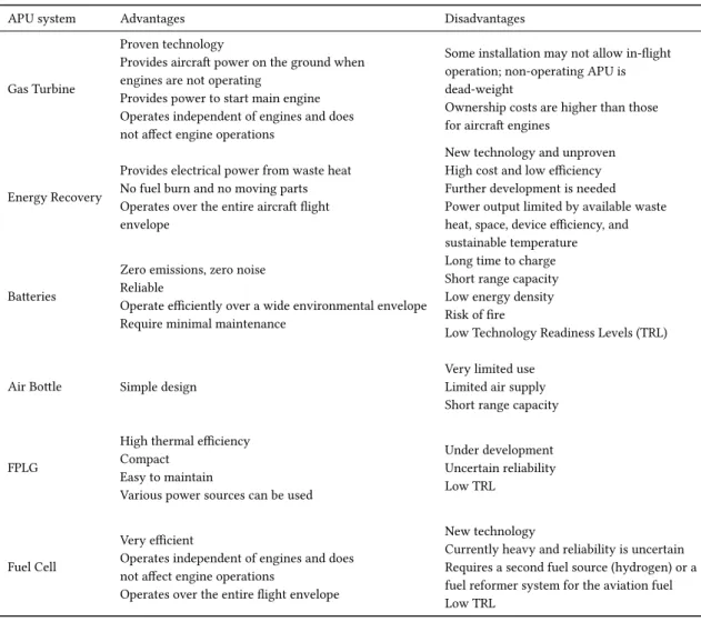
2.4 Advantages and Disadvantages of the different types of APU
Table 2.1: Comparison of the different APUs mentioned in this work.
APU system Advantages Disadvantages
Gas Turbine
Proven technology
Provides aircraft power on the ground when engines are not operating
Provides power to start main engine Operates independent of engines and does not affect engine operations
Some installation may not allow in-flight operation; non-operating APU is dead-weight
Ownership costs are higher than those for aircraft engines
Energy Recovery
Provides electrical power from waste heat No fuel burn and no moving parts Operates over the entire aircraft flight envelope
New technology and unproven High cost and low efficiency Further development is needed Power output limited by available waste heat, space, device efficiency, and sustainable temperature
Batteries
Zero emissions, zero noise Reliable
Operate efficiently over a wide environmental envelope Require minimal maintenance
Long time to charge Short range capacity Low energy density Risk of fire
Low Technology Readiness Levels (TRL)
Air Bottle Simple design
Very limited use Limited air supply Short range capacity
FPLG
High thermal efficiency Compact
Easy to maintain
Various power sources can be used
Under development Uncertain reliability Low TRL
Fuel Cell
Very efficient
Operates independent of engines and does not affect engine operations
Operates over the entire flight envelope
New technology
Currently heavy and reliability is uncertain Requires a second fuel source (hydrogen) or a fuel reformer system for the aviation fuel Low TRL
2.5 Considered parameters for aeronautical application
This work introduces the concept of an HT-PEMFC as an APU. Analyzing some parameters for the study of the fuel cell onboard an aircraft allows the creation of a more viable concept.
2.5.1 Fuel and Oxidant supply
Hydrogen is a promising fuel, but there are some concerns about its production, storage, and distribution aboard an aircraft. Improving these aspects would lead to better use of hydrogen. Figure 2.15 analyses the system efficiency based on the methods for fuel supply and combined with the possible ways of oxidant supplying. This study was made for cruise conditions in a steady-state simulation.
One way to store hydrogen in an aircraft is in pressurized tanks which require large high-pressure vessels. Also, when at a temperature of -253 ºC hydrogen can be stored in a liquid state, i.e., cryogenic hydrogen storage. Despite presenting high energetic power is a complex and expensive process.
Another option is as a dissolved gas in a metal hydride storage system, which is the safest method and is very volumetrically efficient. Although, hydrogen presents low mass energy densities.
Providentially, pure hydrogen is not the only option to run fuel cells. It can be supplied by reformation of various fuels to generate hydrogen, including natural gas, aviation jet fuel, hydrocarbons, among others [8].
Figure 2.15: Evaluation of system efficiency for various hydrogen supply and oxidant supply concepts under cruise operation conditions [43].
In the framework of this study, it is better to supply oxygen from ambient air, or even better cabin air than carrying an oxidizer onboard which would lead to a significant increase in aircraft weight [6].
From here, the most promising architectures for APU application is the integration of pressurized hydro-gen storage and supplying the air from the cabin as it presents the best combination between complexity and efficiency and displays the highest potential for long-range applicability in aircraft structures [43, 6]. Meanwhile, the systems with fuel reforming present the lower efficiency and a more complex system.
Table 2.2: Hydrogen production costs in euros of 1990 [22]. Type of energy Cost of H2 production
(1990e per kWh) Biomass 448 Coal 453 Electricity 439 Natural Gas 219 Oil based 439 Solar 2549
Analyzing Table 2.2, we can assert that the cheapest method to produce hydrogen is from natural gas, while the most expensive process is from solar energy.
After analyzing the cost of hydrogen production per kWh, it is fundamental to interpret the fine composi-tions of the reformed fuel as they directly relate to the performance of a fuel cell system. Therefore, Table 2.3 exhibits the composition of hydrogen (H2), carbon dioxide (CO2), water vapor (H2O) and nitrogen (N2) of several fuels after exposed to steam reforming. Steam reforming tests to different fuels show that methane steam reforming produces a higher volume percentage of hydrogen.
2.5.2 Altitude Sensitivity
Considering fuel cells depending on ambient air, then APUs are limited at very high altitudes due to difficulties associated with reduced air density [48]. As the altitude increases, the ambient air pressure decreases, as well as the stoichiometric factor of the air and the partial pressure of the oxygen.
Table 2.3: Volume percentage composition of products from different processes for producing hydrogen-rich feed for fuel cells [47].
Steam-reforming of Composition of resulting fuel (vol%)
H2 CO2 H2O N2
Methane 64.1 16.3 17.8 1.8
Methanol 61.8 21.1 14.1 3.0
Ethanol 62.6 21.4 12.5 3.5
Gasoline, diesel fuel, and jet fuel 58.2 19.7 20.6 1.5
the voltage response of the fuel cell decreases as the cathode oxygen partial pressure also decreases lead-ing to a performance decline [7]. The drylead-ing of the membrane due to cathode air pressure decline seems to cause the problem as it lowers the voltage of the cell and therefore the maximum operable current. This current drastically affects the power and efficiency of the fuel cell [41].
Several studies suggest that fuel cell systems should operate with high air stoichiometries (often λc≃ 2.5
is used for altitudes higher than 2000m), as it lowers the power loss of the fuel cell due to prevent any cathode concentration depletion [7, 51]. Literature also reveals that there is a fuel efficiency increase of 5% in obtaining air from cabin other than ambient air at high altitude conditions [6, 52]. The reason for that is that using cabin air allows reducing the effects of varying atmospheric pressure.
2.6 Energy and Exergy Analysis
Data obtained from energy and exergy analysis of a system allows respectively, to measure the energy conversion, and to locate, identify and quantify the magnitude of waste and losses for the optimization of a thermal system. Thermodynamics is the science that studies systems and how they interact with their surroundings, governed by the two laws of thermodynamics.
The first law of thermodynamics states that energy cannot be created or destroyed, it can only be trans-formed from one form to another. Hence, the total amount of energy remains the same within a system, for that reason the first law is generally called as the principle of conservation of energy.
The Second Law of Thermodynamics asserts that energy has quality as well as quantity, and actual pro-cesses occur in the direction of decreasing quality of energy. The quantification of energy quality, or the potential to perform work, according to the Second Law, cames from the definition of exergy and entropy properties. Contrary to energy, exergy is consumed in all the actual processes, as entropy is produced. Entropy is never destroyed, is always created in real processes.
Exergy represents the maximum amount of useful work obtained while two systems interact to equilib-rium. The second system is a reference system, generally considered the environment. Exergy depends on the system and the reference environment which is arbitrary. When a system and the environment are at equilibrium the opportunities to perform work cease to exist, this is called the dead state. At the dead state, exergy is null because it is no longer possible to make changes between the two systems or any interaction [18].
Energy and exergy analysis are complementary. While the energy balance allows a quantitative interpre-tation of the energy involved, the exergy balance provides qualitative information of that energy, pointing out the critical points of the system due to its irreversibilities and losses. This information can be used for designing, evaluating, optimizing and improving energy systems.
Efficiency based on First Law focuses its attention on reducing losses by treating all forms of energy as equal, whether mechanical or thermal energy. Exergy efficiency is generally lower than energy efficiency,
due to the presence of process irreversibilities, which destroy part of the initial exergy. Nevertheless, the exergetic efficiency provides a more accurate understanding of system performance.
Fuel cells are not heat engines yet produce heat that must be removed. Depending on the size of the system, the temperature of the available heat and the requirements of its application this thermal energy can be either rejected, used to produce steam or hot water, or converted to electricity via a gas turbine or steam bottoming cycle or some combination of this [40]. One way to increase the system efficiency is by one of the methods of heat recovering described above. The use of the water produced or the highly efficient heat recovery must be planned as part of the basic engineering structure.
2.6.1 Thermodynamic Balances
In thermodynamics, an abstract fixed region can be applied to a system to solve conservation principles. The fixed region studies the masses and different forms of energy crossing a defined boundary (control surface) of the region and is known as control volume [18].
The general balance equation for any quantity in a system can be written as
Input + Generation− Output − Consumption = Accumulation V ariation (2.3)
From this equation, we can write the mass, energy, entropy, and exergy balances. Furthermore, the first and second law efficiency are also defined from balance equations.
2.6.1.1 Mass Balance
For steady state and steady flow conditions the total mass flow rate entering the control volume remains unchanging in time. Thus, the inlet mass flow rate ( ˙min) is equal to the outlet mass flow rate ( ˙mout). In
these conditions, the principle of mass conservation, on rate form, can be defined by Eq. 2.4. ∑ ˙ min= ∑ ˙ mout (2.4)
where all incoming and outgoing streams are considered.
2.6.1.2 Energy Balance
For a control volume at steady state, the total amount of energy present at any instant remains constant, i.e., the total energy rate going in ( ˙Ein) and out ( ˙Eout) across the boundary are equal as can be seen in Eq.
2.5. ∑ ˙ Ein= ∑ ˙ Eout (2.5)
The conservation of energy in a control volume, assuming steady-state flow and neglecting potential and kinetic differences, can be expressed by Eq. 2.6.
˙ Qcv− ˙Wcv+ ∑ ˙ min¯hin− ∑ ˙ mout¯hout = 0 (2.6)
where ¯h represents the specific enthalpy, ˙Qcvand ˙Wcvare the energy rates transfer by heat and by work,
respectively, across the control surface. The work rate is considered positive when produced by the system, in other words, whenever it is transferred from the system to the surroundings.
![Figure 2.1: Supermarine PB31E Nighthawk with an auxiliary power unit installed aft of the main engine [11].](https://thumb-eu.123doks.com/thumbv2/123dok_br/19170478.940968/31.892.331.605.650.859/figure-supermarine-nighthawk-auxiliary-power-unit-installed-engine.webp)
![Figure 2.4: Distribution of energy for the airplane and its power consumption [6].](https://thumb-eu.123doks.com/thumbv2/123dok_br/19170478.940968/33.892.305.632.161.438/figure-distribution-energy-airplane-power-consumption.webp)
![Figure 2.7: A proposed energy recovery APU [27].](https://thumb-eu.123doks.com/thumbv2/123dok_br/19170478.940968/36.892.235.614.109.349/figure-a-proposed-energy-recovery-apu.webp)
![Figure 2.13: Antares DLR-H2 platform [42]](https://thumb-eu.123doks.com/thumbv2/123dok_br/19170478.940968/41.892.267.670.104.393/figure-antares-dlr-h-platform.webp)
![Figure 2.14: SOFC-GT APU implemented at the tail end of an aircraft [21].](https://thumb-eu.123doks.com/thumbv2/123dok_br/19170478.940968/42.892.113.669.107.300/figure-sofc-gt-apu-implemented-tail-end-aircraft.webp)
![Figure 2.15: Evaluation of system efficiency for various hydrogen supply and oxidant supply concepts under cruise operation conditions [43].](https://thumb-eu.123doks.com/thumbv2/123dok_br/19170478.940968/44.892.187.665.108.407/figure-evaluation-efficiency-various-hydrogen-concepts-operation-conditions.webp)
![Table 2.3: Volume percentage composition of products from different processes for producing hydrogen-rich feed for fuel cells [47].](https://thumb-eu.123doks.com/thumbv2/123dok_br/19170478.940968/45.892.220.717.158.288/volume-percentage-composition-products-different-processes-producing-hydrogen.webp)