Resumo
A perfuração computadorizada e a temporização eletrônica das detonações são dois avanços tecnológicos que têm tido um papel importante na atualização dos métodos de escavação com explosivos. Apesar disso, a temporização eletrônica dos detonadores ainda é uma solução técnica pouco frequente para problemas de detonação de precisão. Com base em uma extensa pesquisa bibliográica, esse artigo revisa os resultados alcançados e as principais vantagens esperadas dos dispositivos eletrônicos de iniciação. Após descrever as características primárias desses detonadores, alguns elementos são considerados, a im de que sejam melhor compreendidas as aplicações em diferentes condições, tanto em céu aberto quanto em subterrâneo, a extensão do número de tempos de retardo, a liberdade na escolha dos intervalos de tempo entre as detonações, a precisão da temporização, a redução das vibrações, o controle do overbreak e da fragmentação. Os resultados são comparados com aqueles obtidos por meio de dispositivos pirotécnicos de temporização e discutidos nas considerações inais.
Palavras-chave: Detonador eletrônico, detonador pirotécnico, perfuração e detonação, detonação de precisão, precisão na temporização.
Abstract
Computerized drilling and the electronic timing of detonations are two technological breakthroughs which have had an important role in updating drilling and blasting excavation methods, although the electronic timing of detonators is still a comparatively infrequent technical solution to precision blasting problems. On the basis of an extensive collection of published cases, this paper reviews the successes achieved and the main expected advantages from the electronic ignition devices. After describing the primary characteristics of these detonators, some elements will be considered, in order to better understand their applications in different conditions, both in open pit and underground sites: extension of the time delay number, freedom in the choice of time intervals between detonations, timing accuracy, reduction of vibrations, control of back-break and fragmentation. The results are compared to those obtained by pyrotechnical timing devices, and summarized in the concluding remarks.
Keywords: Electronic detonator, pyrotechnic detonator, Drill &Blast, precision blasting, timing accuracy.
Marilena Cardu Department of Environment, Land and Infrastructures (DIATI), Politecnico di Torino, Italy. IGAG C.N.R., Turin, Italy. [email protected]
Alessandro Giraudi Department of Environment, Land and Infrastructures (DIATI), Politecnico di Torino, Italy.
Pierpaolo Oreste Department of Environment, Land and Infrastructures (DIATI), Politecnico di Torino,
Italy. IGAG C.N.R., Turin, Italy. [email protected]
A review of the beneits of
electronic detonators
Uma revisão das vantagens dos
detonadores eletrônicos
1. Introduction
Electronic devices (ED) were devel-oped from an idea originated in the 1990s. Till now, EDs have been developed in Italy during the testing stage. They can fulil the demand for increased accuracy, but their costly technology has hindered their expected growth.
In an ED, delay is achieved electroni-cally; a computer chip is used to control delay timing. An integrated circuit chip and a capacitor internal to each detonator control the initiation time.
An electronic detonator has a num-ber of advantages, e.g. higher precision, improved blasting result owing to a wide
range of delays, reduction of airblast/ ground vibration, and safe use in extrane-ous electric environments, and the possi-bility of limiting the amount of detonators per shot. It has some disadvantages too, e.g. higher cost per detonator and the need for intensive training for users.
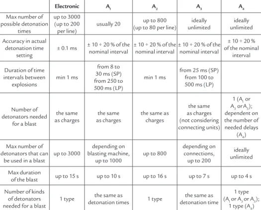
Conventional timing systems, to be compared to electronic timing, are listed in Table 1 and shown in the sketches (Figure 1). Electronic timing, in its turn, comprises electric detonators that include an ignition energy storage device and a programmable electronic timer, wired together with the programming, energy feeding and
activation system. This makes it possible to decide freely, and obtain accurately, whatever distribution of detonation times is desired by the blast designer. Moreover, mixed systems (electronic + A3, electronic + A4) are possible.
Since the electronic detonators (and other components of the system, including the trained operator) are more expensive than conventional systems, the intrinsic advantages arising from the electronic tim-ing option deserve to be weighted against the higher cost.
In Table 2, some relevant features of electronic systems are compared to
Table 1
Commonly used timing systems.
Systems Components Scheme
Electric with pyrotechnic delay elements
Blasting machine, wires, ignition pill, delay element, primary or special NP (Non Primary) charge A1
Electric with separate circuits powered in sequence
Blasting machine (including a timer), wires,
ignition pill, primary or special NP charge A2
Non-electric with shock tube and pyrotechnic delay elements
Any source of priming shock, shock tubes, pyrotechnic delay elements, detonating primary
or special NP charge (for branching and for main charge detonation).
A3
Non-electric with detonating cord and pyrotechnic delay elements
Any kind of detonator, detonating cord,
pyrotechnic delay elements (relays). A4
Safety fuse Fuse ignition devices, fuse, blasting caps A5
Mixed systems Most common: A1+ A2, A1+ A3, A1+ A4, A5+ A3, A5+ A4,
but more complex system are possible
Figure 1
conventional systems. The safety fuse is disregarded, being used practically only in A5 + A3 and A5 + A4 mixed systems.
With regard to accuracy, there are some other considerations: lashover (ow-ing mainly to inaccuracy in drill(ow-ing and charging) is not affected by the timing systems; the detonation of a charge can last some ms to some ms depending on the explosive and the size of the cartridge; and inaccuracy of ms in the detonation starting time deinition implies an inac-curacy of some metres in knowing the space travelled by a detonation front in the explosive, by a shock front in a rock, or by the tip of a propagating crack. In practice, in addition to the congenital inaccuracy due to type of explosive and to its geometry, the inaccuracy (even only a few ms) due to the timing sequence must be taken into account.
Moreover, geometrical and geome-chanical details of the mean are described forcibly in a statistical way, which adds some uncertainty: absolute accuracy of the results’ prediction is not possible, even when laboratory tests on artiicial materi-als are carried out.
More information is available in lit-erature (Reisz et al., 2006). The accuracy of detonation times, however, rules out a great number of random effects, provided that the same care is taken in reining the explosion timing, drilling, charging and stemming.
In general, accurate and lexible
tim-ing allows blasters to make small hole-to-hole and row-to-row changes to account for drilling inaccuracies. Adjusting the blast design to actual conditions can im-prove safety and fragmentation, which can cut costs by optimizing the loading and hauling cycle, increasing crusher through-put, and reducing the amount of oversize handling and secondary breaking.
A great advantage of this type of detonator is its safety in the case of any stray currents, radar radiation or other electromagnetic interference, as well as its safety in the case of misuse. It cannot be ired simply by a battery or by other electric sources.
In addition, precise and variable delay timing organization enhances high-wall stability and bench crest preservation, resulting in safer mine operations and in lower blast-induced ground vibrations. These improvements allow for more accurate placement of boreholes for sub-sequent blasts. Optimization of the blast design to take greater advantage of the electronic detonators’ precision expands the blast pattern and reduces the explosive consumption, without negatively affecting production (Sharma, 2009).
Electronic detonators are generally programmable in 1 ms increments and have a delay accuracy (scattering) as low as ± 0.1 ms.
Main blasting opportunities with electronic detonators are: frequency and peak particle velocity (ppv) control; large
open pit patterns (long delays); easiness of multiple decking initiation (minimal delay intervals); large stope blasting; frag-mentation optimization; and delay period re-evaluation.
Incorrect timing of explosions (too long or too small an interval) affects the blast result according to different mechanisms: • Seismic effect may be increased
be-cause of unwanted cooperation, or because the actual burden of a charge exceeds the ideal planned burden (as the rock to be broken by the previous explosion should be still firmly in place) or because of positive interfer-ence effects.
• Fly rock throw can be increased, either because rock removal by the previous explosion is in a too advanced stage, or because it is still insuficient; in the irst case, burden is too small, in the second is too high and the ejection of stemming can take place, due to gun-effect.
• A lack of balance of the actual burdens between the charges of the blast gives rise to localized backbreak effects and to irregularities of the residual face and irregular fragmentation, even when the ideally expected burdens are measured accurately.
• In multi-row blasting, when the break-ing line of a row is the free (or “almost free”) face of the next row, any irregu-larity causes further irreguirregu-larity in the fragmentation.
Electronic A1 A2 A3 A4
Max number of possible detonation
times
up to 3000 (up to 200 per line)
usually 20 up to 800 (up to 80 per line)
ideally unlimited
ideally unlimited
Accuracy in actual detonation time
setting
± 0.1 ms ± 10 ÷ 20 % of the nominal interval
± 10 ÷ 20 % of the nominal interval
± 10 ÷ 20 % of the nominal interval
± 10 ÷ 20 % of the nominal
interval
Duration of time intervals between
explosions
min 1 ms
from 8 to 30 ms (SP) from 250 to 500 ms (LP)
min 1 ms
from 25 ms (SP) from 100 to 500 ms (LP)
Number of detonators needed
for a blast
the same as charges
the same as charges
the same as charges
the same as charges (not considering connecting units)
1 (A1 or
A3 orA5); dependent on the number of needed delays
(A4)
Max number of detonators that can
be used in a blast
up to 3000
depending on blasting machine,
up to 1000
up to 800
depending on connections,
up to 200
ideally unlimited
Max duration
of the blast up to 15 s up to 10 s up to 16 s up to 7 s up to 4 s
Number of kinds of detonators needed for a blast
1 type the same as
detonation times 1 type
the same as detonation time
1 type (A1 or A3 or A5);
1 type (A4)
The present work is the result of a detailed analysis of literature: some works refer to underground stopes, while others
examine open pit mines and quarries. In order to evaluate the beneits from the use of EDs, the data considered (seismic
effects, fragmentation, and overbreak) are deined in the following, in percentage terms, according to the ratio (1):
value % = data ED - 1 .100
data PD
(
)
(1)2. Opencast works
The study by Sharma (2009) ex-amines the structural response to blast-induced ground vibration. He underlines the importance, from an environmental point of view, of minimizing vibrations induced in urban dwellings by blasting. The maximum response of a building to blast-induced ground vibration occurs whenever the frequency of the ground vibration matches the natural resonant frequency of the structure: if there is little or no energy at the resonant frequency of the structure, the structural response to the vibration will be negligible.
By choosing delay times (∆t) that cre-ate “destructive interference” at frequen-cies that are favoured by local geology, the vibration that excites structural elements could be reduced. In this method, accu-rate delay times are crucial for effective vibration control. Electronic detonators have less than 1 ms scatter. In this light, researchers have started to ind both limi-tations and different potential in this new technique of controlling blast vibration.
The computer analysis determines the application of delay timing between holes, rows and decks which would pro-duce the most favourable blast-inpro-duced vi-brations for buildings and urban dwellings. In Table 3 and Figure 2, data per-taining to ED and to pyrotechnic
detona-tors (PD) are shown.
A reduction of the ppv is noticeable when ED are used: this trend is shown in Figure 2, where scaled distances are plot-ted against peak particle velocities; data refer to 18 blasts that were ired during testing on site, 9 of them with PD and the rest with ED.
The study by Bartley et al. (1998) refers to the employment of a 60 kg/hole charge per delay (cpd); the events were monitored at a distance varying from 400 m to 822 m. Deacon et al. (1997) refer to another case, in which the cpd were in the 20-46 kg/hole range using PD, and in the 16-20 kg/hole range using ED; the events were monitored at a distance of 140 to 180 m (using PD), and from 130 to 160 m (using ED).
During mining operations in a South African quarry (quartzite and sandstone) McFerren et al. (2004) adopted ED and PD (shock tube). The cpd was 230 kg and the powder factor was 0.42 kg/m3. The
ppv monitored by Chavez et al. (2003) are the results of the blast with the compari-son of ED vs. PD, with interhole delays of 12 ms in a French limestone quarry. In the same paper, the reductions of ppv
generated by ED in another quarry are reported; 40 to 55 % with respect to the
ppv obtained by PD.
Few authors evaluate the frequency increase when EDs are employed. In par-ticular, by using the relation F = 1000/ delay to get the dominant frequency, the expected value of the frequency can be calculated (Deacon, 1997; Chavez, 2003).
As shown in Table 4, by adopting ED instead of PD an increase of frequency values is observed.
Also, the airblast levels were re-corded by Baka Abu (2002) and McFerren et al. (2004) during mining operations. The irst author obtained these results: the airblast levels were reduced from 127 dB to 108 dB (-15 %) using ED instead PD. McFerren et al. (2004), during blasts initiated with ED instead of PD, observed a reduction of 3 %.
Another comparison between ED and PD is the rock fragmentation degree obtained from the blast (Table 5).
Grobler (2003) refers to the results obtained in surface mining, particularly on the log-linear plot of muck pile; ED produced a reduction in the upper size and the ines. In contrast, the grain size distri-butions related to ED, evaluated by König et al. (1994) and Havermann et al. (1995), are systematically higher compared to PD. The study by Bartley (2001) of the post-blast muck pile excavation indicated a 25% reduction in dig time using ED.
Table 3
Comparison between different ppv values, using ED and PD iring systems separately.
Authors: ppv Min ppv Max
ED PD % ED PD %
Deacon C., Duniam P., Jones M., 1997
8.85 mm/s 12.18 mm/s -27 13.54 mm/s 25.8 mm/s -47
Bartley D. A., Trousselle R.,
1998
Rad. 0.25 mm/s 0.51 mm/s -51 5.21 mm/s 5.72 mm/s -9
Vert. 0.25 mm/s 0.38 mm/s -34 4.06 mm/s 3.94 mm/s 3
Tran. 0.64 mm/s 0.76 mm/s -16 7.49 mm/s 10.7 mm/s -30 Bartley D. A.,
Winield B., McClure R., Trousselle R.
2000
Rad. 4.57 mm/s 3.3 mm/s 38 8.89 mm/s 5.84 mm/s 52
Vert. 2.54 mm/s 3.3 mm/s -23 6.1 mm/s 4.57 mm/s 33
Tran. 2.79 mm/s 5.08 mm/s -45 14.2 mm/s 7.11 mm/s 100
\\ R., Chantry R.,
2003 3.0 mm/s 3.8 mm/s -21 5.0 mm/s 9.8 mm/s -49 McFerren W.,
Moodley P., 2004
Figure 2 The ppv data from Deacon et al. (1997)
and Bartley et al. (1998) have been processed to obtain a comparison between ED and PD.
Authors ED PD %
Bartley D. A., Trousselle R. 1998 26 ÷ 64 Hz 20 ÷ 47 Hz 30 ÷ 36 %
Carter R. A., 2002 26 ÷ 39 Hz 8 ÷ 20 Hz > 95 %
Bartley D. A., Winield B., McClure R.,
Trousselle R., 2000 13 ÷ 63 Hz 19 ÷ 55 Hz -31 ÷ 15 %
McFerren W., Moodley P., 2004 30 ÷ 71 Hz 26 ÷ 57 Hz 15 ÷ 25 %
Table 4 Comparison between different frequency values using ED and PD iring systems separately.
Table 5 Rock fragmentation as a result of a blast,
considering ED and PD, respectively.
Authors Max Size Mean Size Min Size
ED PD % ED PD % ED PD %
Havermann T.
et al., 1995 1500mm 1800mm -17% 255mm 410mm -38% 60mm 100mm -40%
Deacon C., Duniam P.,
Jones M., 1997 680mm 900mm -24% 125mm 200mm -37% 20mm 50mm -60%
Bartley D. A., Trousselle R.,
1998 1115mm 1485mm -25% 236mm 291mm -19% 13mm 21mm -38%
König R., Petzold J.,
1998 1100mm 1500mm -27% 250mm 400mm -37% 75mm 100mm -25%
Petzold J., Hammelmann F.
2000
812.8mm passing 406.4mm passing 202.3mm passing
78.30% 63.20% 19% 34.90% 24.10% 45% 9.40% 4.80% 96%
Bartley D. A.
et al., 2000
-203mm passing
214mm 320mm -33% 76.70% 55.90% -37%
Mckinstry R., Floyd J., Bartley D., 2002
90 % passing 50% passing 10% passing
3.98 * 7.07 * -44% 2.87 * 2.92 * -2% 1.44 * 0.99 * 45%
Grobler H. P., 2003
90% passing 50% passing 10% passing
500mm 750mm - 33% 70mm 70mm 0% 10mm 3mm 233%
McFerren W., Moodley P.,
2004
53mm sieve aperture 13.2mm sieve aperture 2mm sieve aperture
10% 17% -41% 50% 75% -33% 90% 95% -5%
* (block size, diameter of the equivalent sphere).
0,1 1 10 100
1 10 100 1000
Scaled distance [m/kg ]1/2
P
P
V
[
m
m
/s
] PD Bartley 1998
Moreover, the crushing operations show a reduction of electric power consump-tion (kWh/t) of about 6–10 % if EDs are employed.
When EDs are employed, thanks to the improvement of the fragmentation, the block size distribution is upgraded (in comparison with PD) as follows:
• maximum block size: reduction of 24 %.
• mean size: reduction of 25 %. • minimum size: reduction of 10 %.
3
. Underground works
In the last 15 years, some appli-cations of the electronic detonators have been developed, to be employed underground, especially in tunnelling. In some cases, electronic devices can be used even in mixed systems, as shown in Figure 3.
The study by Svärd (1993) refers to the employment of a 3 kg/hole charge per delay (cpd), while Thomas-son (2000) describes an event in which a 400 g/hole cpd was adopted.
Cho (1997) refers to another case, in which the cpd were in the 125–500 g/hole range in case of PD, and in the 125–375 g/hole range in case of sequential blasting. The events were monitored at a distance of 20 to
33 m (in the case of PD), and from 21 to 42 m (in the case of sequential blasting). See Table 6.
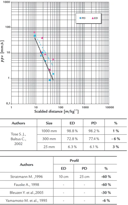
Some experimental blasts were carried out by Wetherelt (2007) for a comparative study of ppv in a tunnel. In the irst blast, PDs (non electric detonators) were employed, while in the second EDs (with the same delay times as in the previous case) were used. The results obtained by moni-toring ground vibrations are shown in Figure 4; the cpd employed for the tests was 1.60 kg.
The comparison of an ED vs PD iring system in underground mining activities is not so relevant in terms of muck-pile fragmentation (see Table 7),
as quoted by Tose and Baltus (2002). The authors, whose works are quoted in Table 8, point out that an improvement of the blast’s precision and a reduction of the overbreak is noticeable, thanks to the employment of electronic detonators. In tunnel driving, more advantageous results can be obtained in the quality of the blast: overbreak lowers by more than 40 %, by resorting to the mixed system ED-PD, realized by adopting PD for the cut and for the stoping holes and ED for the contour holes. EDs are employed most of all in the contour holes, if they have to be ired simultaneously.
Figure 3
Priming pattern by employing the mixed system ED-PD (König R., 1994, Modiied).
Authors ED (mm/s) PD (mm/s) %
Svärd J., 1993
33 caps per round 4 8 -50
44 caps per round 9 16 -44
Thomasson C., 2000 - 7 12.1 -42
Cho Y. D. et al., 1995 sequential blasting - -14 ÷ 18
Wetherelt A., 2007 2.25 - 65.02 0.83 – 45.72 40 ÷ 292
Table 6
Comparison between different ppv values by using ED and PD iring systems respectively.
Dynashoc SP periods 1-20
firing times: 25 to 500 ms
ED number zero
Detonating cord ED period 60 interval 10
ms firing times: 600 ms
Figure 4
ppv data (taken from Wetherelt A.
2007) have been processed to obtain a comparison between ED and PD.
Table 7 Rock fragmentation as a result of a blast,
considering ED and PD, respectively.
Table 8 Comparison between different proile accuracy values using ED and PD iring systems separately.
Authors Size ED PD %
Tose S. J., Baltus C., 2002
1000 mm 98.8 % 98.2 % 1 %
300 mm 72.8 % 77.4 % - 6 %
25 mm 6.3 % 6.1 % 3 %
Authors Proil
ED PD %
Stratmann M. ,1996 10 cm 25 cm -60 %
Fauske A., 1998 - - -60 %
Bleuzen Y. et al.,2005 - - -30 %
Yamamoto M. et al., 1995 - - -6 %
4. Conclusions
The results of this review show that the employment of EDs is advantageous in terms of vibration reduction, increased frequencies, airblast, improved fragmenta-tion in the muck pile, diggability, crushing cost saving (less energy used during the primary and secondary fragmentation), and control of overbreak, which allows greater proile accuracy. Nevertheless, EDs’ advantages are satisied where an
accurate design of the blast and an ad-equate hole’s drilling and charging are guaranteed.
As discussed, the electronic detona-tors provide more accurate timing than the conventional pyrotechnic detonators which rely on the combustion speed of a pyrotechnic composition. The timing accuracy capability of the electronic deto-nator allows for:
• More eficient application of explosive energy.
• Improved muck size uniformity. • Increase in excavation productivity. • Cost saving in excavation operations. • Improved public acceptance of blasting. • An additional benefit of electronic
detonators. i.e. the improved control of blast-induced vibrations and airblast.
5. References
BARTLEY, D. A., TROUSSELLE, R. daveytronic digital detonator testing in a vibration sensitive environment. In: ANN. CONF. ON EXPLOSIVES AND BLASTING TECHNIQUE, 24. New Orleans, Louisiana, USA ISEE, 1998. p. 247-261.
BARTLEY, D. A., WINFIELD, B., MCCLURE, R., TROUSSELLE, R. Electronic detonator technology: Field application and safety approach. In: EFEE WORLD CONFERENCE ON EXPLOSIVES AND BLASTING, Munich, 2000. p. 149-158.
0,1 1 10 100 1000
1 10 100 1000 10000
Scalded distance [m/kg ]1/2
p
p
v
[
m
m
/s
]
BARTLEY, D. A. Field applications and quantiication of electronic detonator technology. ISEE, INT. CONF. ON EXPLOSIVES & BLASTING TECHNIQUE, International Society of Explosives Engineers, 1-19. 2001.
BAKA ABU J. The Implementation of the Smartdet Universal System at Damang Gold Mine, Ghana. Marcus Evans Conference, New Paradigm Shift in Drilling and Blasting, Johannesburg, South Africa, 2002.
BLEUZEN, Y., MONATH, F., QUARESMA, M., JOÃO, M. Tunnel blasting in a sensitive environment using electronic detonators. The Journal of Explosives Engineering, p. 6-14, sep/oct, 2005.
CARTER, R. A. Plugging in to digital detonation: electronic sequencing and initiation systems can improve blasting performance and reduce neighbor complaints. Rock Products, p. 28-30, may, 2002.
CHAVEZ, R., CHANTRY, R. Actual beneits from new technologies related to constant timing with electronic detonators and uniform energy control. In: EFEE WORLD CONFERENCE ON EXPLOSIVES AND BLASTING, 2. Prague, 2003, p. 303-311. CHO Y. D., PARK, B. K., LEE, S. E., LIM, H. U. Application of full-face round by the
sequential blasting machine in tunnel excavation. In: ISEE INT. CONF. ON EXPLOSIVES & BLASTING TECHNIQUE, 21. International Society of Explosives Engineers, p. 108-120, 1995.
DEACON C., DUNIAM, P., JONES, M. Improved blast control through the use of programmable delay detonators. In: ISEE INT. CONF. ON EXPLOSIVES & BLASTING TECHNIQUE, 23. International Society of Explosives Engineers, p. 55-68, 1997. FAUSKE, A. La construccion de tuneles urbanos en Noruega. Rocas y Minerales, p. 62-74,
july, 1998.
GROBLER, H. P. Using electronic detonators to improve all-round blasting performance. International Journal for Blasting and Fragmentation, v. 7, n. 1, p. 1-12, 2003.
HAVERMANN, T., VOGT, W., PLAUMANN, G., KÖNIG, R., THOMAS, K. Digitale Haufwerkanalyse von elektronisch gezündeten Sprengungen im Steinbruch Groß-Bieberau der Oden-wälder Hartstein-Industrie GmbH (OHI). Nobel Hefte, n.1, p. 1-9, 1995. KÖNIG, R. Three modern iring methods are on choice. Nobel Hefte, n. 1, p. 1-12, 1994. KÖNIG, R., PETZOLD, J. Diez años de experiencia con el sistema electrónico de iniciacion
‘DYNATRONIC’. Rocas y Minerales, p. 60-66, nov., 1998.
MCFERREN, W., MOODLEY, P. Electronic detonator success: an african story”. 30thISEE
Int. Conf. on Explosives & Blasting Technique. International Society of Explosives Engineers, p. 1-12, 2004.
MCKINSTRY, R., FLOYD, J., BARTLEY, D. Electronic detonator performance evaluation. The Journal of Explosives Engineering, p. 12-22, May/Jun, 2002.
PETZOLD J., HAMMELMANN, F. The second generation of electronic blasting systems. Int. Conf. on Explosives & Blasting Technique, EFEE, p. 159-164, 2000.
REISZ W., MCCLURE, R., BATLEY, D. Why the 8 ms rule doesn’t work. The Journal of Explosives Engineering, p. 14-22, (Jul/Aug), 2006.
SHARMA, P. D. Electronic detonators: Results in substantial techno-economic beneits for large mining operations. Mining Engineers’ Journal, India (February), 2009.
STRATMANN, M. Moderne Bohr-und Sprengverfahren beim Vortrieb des Mitholztunnel. Nobel Hefte, 1/2, p. 31-39, 1996.
SVÄRD, J. Possibilities with accurate delay time. FRAGBLAST Rock Fragmentation by Blasting,1, p. 71-78, 1993.
THOMASSON, C. Le tir aux détonateurs électroniques dans le tunnel de foix. Tunnels et Ouvrages Souterrains, p. 359-361, Nov/Dec, 2000.
TOSE, S. J., BALTUS, C. Comparison of the fragmentation results from the use of electronic detonators and shock tube initiating systems under similar mining conditions. Fragblast 7 Rock Fragmentation by Blasting, Beijing, p. 50-53, 2002.
WETHERELT, A. A comparative study of ppv analysis of tunnel rounds using both non electric and programmable electronic detonation. 33rdISEE Int. Conf. on Explosives &
Blasting Technique, International Society of Explosives Engineers, p. 10, 2007.
YAMAMOTO, M., ICHIJO, T. TANAKA, Y. Smooth blasting with the electronic delay detonator. 21stISEE Int. Conf. on Explosives & Blasting Technique, International Society
of Explosives Engineers, p. 144-156, 1995.