A Decision tree and Conditional Median Filter Based Denoising
for impulse noise in images
Shiby. S, PG Scholar
1, Asha Sunil, Asst.Professor
2*(Department of electronics and communication, Younus College of Engineering and Technology, kollam dist., India)
** (Department of electronics and communication, Younus College of Engineering and Technology, kollam dist., India)
ABSTRACT
Impulse noise is often introduced into images during acquisition and transmission. Even though so many denoising techniques are existing for the removal of impulse noise in images, most of them are high complexity methods and have only low image quality. Here a low cost, low complexity VLSI architecture for the removal of random valued impulse noise in highly corrupted images is introduced. In this technique a decision- tree- based impulse noise detector is used to detect the noisy pixels and an efficient conditional median filter is used to reconstruct the intensity values of noisy pixels. The proposed technique can improve the signal to noise ratio than any other technique.
I.
INTRODUCTION
Now a day’s visual information transmitted in the form of digital images is becoming a major method of communication, but the image obtained after transmission is often corrupted with noise. Noise hides the important details of images. To enhance the image qualities, we have to remove noises from the images without any loss of information.
Image denoising is one such powerful methodology which is deployed to remove the noise through the manipulation of the image data to produce very high quality images. These noises are appeared on the images in different ways :at the time of acquisition due to noisy sensors, due to faulty scanner or due to faulty digital camera, due to transmission channel errors, due to corrupted storage media. Impulse noise in image is present due to bit errors in transmission or induced during the signal acquisition stage. There are two types of impulse noise, like salt and pepper noise [9] and random valued noise. Salt and pepper noise can corrupt the images where the corrupted pixel takes either maximum or minimum gray level. The removal of noise from image is known as denoising. The important property of a good image denoising model is that, it should completely remove the noise as far as possible as well as preserve edge, i.e. linear filtering and non linear filtering. In linear filtering denoising techniques [5],[6],[7],[10] is directly applied to the image pixel without checking the availability of noisy and non noisy pixels. The example of linear filtering is mean filter. The disadvantage of this filter is it will affect the quality of non noisy pixels. In the case of non linear filter,
this is done by two steps. First step detection then filtering. Non linear filtering techniques are implemented widely because of their superior performance in removing salt and pepper noise and also preserving fine details of image. There are many works on the restoration of images corrupted by salt and pepper noise. The median filter was once the most popular non linear filter for removing impulse noise, because of its good denoising power and computational efficiency. Median filters are known for their capability to remove impulse noise as well as preserve the edges. In image processing [2],[3] many methods have been developed for the removal of impulse noise in images. The standard median filter [10] is such technique for the removal of image impulse noise. This technique has the disadvantage of poor image quality obtained after the de-noising. This might blur the image because it modifies both noisy and noisy free pixels. In order to overcome this disadvantage of standard median filter new technique switching median filter have been introduced. The switching median filter consists of two main steps an impulse detector to detect the noisy pixels and an impulse noise filter filters the noisy pixels. The advantage of this technique is that it effectively removes the noisy pixels only rather than the whole pixels of the image to avoid causing damage on noisy-free pixels. Luo proposed another technique An Alpha Trimmed Mean Based Method (ATMBM) [11]. It uses alpha trimmed mean for impulse noise detection and the detected noisy pixel values is replaced by the original detected value and the median value of its local window. A Differential Rank Impulse Detector (DRID) was presented in [4]. In DRID impulse detector works on the comparison
of signal samples within a narrow rank window by considering both rank and absolute values. Based on the complexity the de-noising techniques have been classified into lower complexity [5],[6] and higher complexity technique [4],[9] .The lower complexity technique provides a good quality for the reconstructed image. In the field VLSI reduction of chip area is found to be one important criteria and the new denoising technique decision tree based de-noising method (DTBDM) using a conditional median filter is introduced for the removal of salt and pepper noise in images. The decision tree is a simple but powerful tool for the complex multivariable analysis. It can breakdown a complex decision making process into simpler one and finds better solution for the problem. To enhance the effects of removal of impulse noise the reconstructed pixels have been written back as a part of input data. Especially, it can remove the noise from corrupted images efficiently and requires no previous training.
II.
PROPOSED DECISION TREE AND CONDITIONAL MEDIAN FILTER BASEDDENOISING METHOD
In this method a 3×3 mask is used for the denoising of the image. Let us consider the image pixel to be deniosed is located at the coordinate (i,j)
and it is denoted as pi,j and its luminance value is named as fi,j as shown in Fig. 1. We divide eight pixel values except the central pixel within the mask into two sets: WTopHalf and WBottomHalf. They are given as
WTopHalf = {a,b,c,d}. (1)
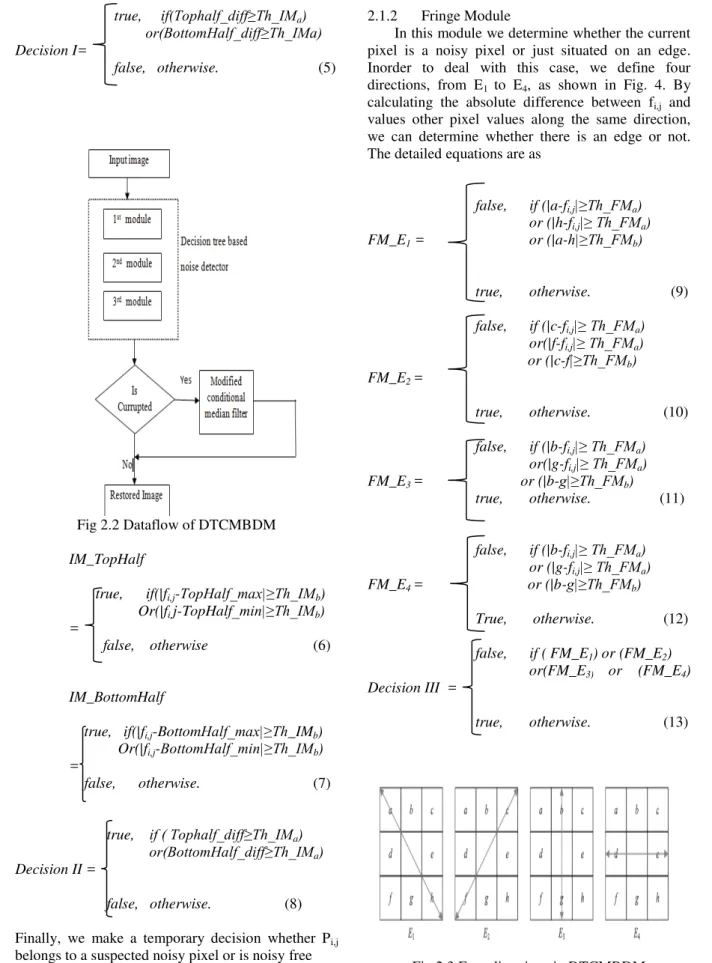
WBottomHalf = {e,f,g,h}. (2) The main components of decision tree and conditional median filter based denoising method (DTCMBDM) Decision tree based impulse detector and conditional median filter. The detector determines whether pi,j is a noisy pixel by using the decision tree and the correlation between pixel pi,j and its neighboring pixels. If the result is positive, a modified conditional median filter generates the reconstructed value. Otherwise the value will be kept unchanged. The design concept of DTCMBDM is shown in fig. 2.
Fig 2.1 A 3×3 mask centered on Pi,j
are decision-tree-based impulse detector and conditional median filter. The detector determines whether pi,j is a noisy pixel by using the decision tree and the correlation between pixel pi,j and its neighboring pixels. If the result is positive, a modified conditional median filter generates the reconstructed value. Otherwise the value will be kept unchanged. The design concept of DTCMBDM is shown in fig. 2.
2.1 Decision- Tree Based impulse detector
We can determine whether the Pi,j is a noisy pixel using the correlation between Pi,j and neighboring pixels [10]. In the decision tree based impulse noise detector we have three modules-isolation module (IM), fringe module (FM), Similarity module (SM). Three concatenating decisions of these modules build a decision tree. The decision tree is a binary tree and can determine the status of Pi,j by using different equations in three different modules. If the result of the isolation module is negative we can say that the current pixel belongs to noisy free. If the result is positive it means that the current might be a noisy pixel or just situated on an edge. The fringe module is used to confirm the result. If the current pixel is situated on an edge, the result of fringe module will be negative (noisy free), otherwise the result will be positive. If the isolation module and fringe module cannot determine whether the current pixel belongs to noisy free, similarity module is used to confirm the result. It compares the similarity between current pixel and its neighboring pixels. If the result is positive, Pi,j is noisy pixel; otherwise it is noise free. The following section will explain the three modules in detail.
2.1.1 Isolation module
Isolation module is the first module. In this module we check whether the current pixel is an isolation point by observing the smoothness of the surrounding pixels. The pixel with shadow suffering from noise have low similarity with the neighboring pixels is called isolation point. The difference between it and its neighboring pixel value is large. Using this concept, we determine the maximum and minimum luminance values in WTopHalf, named as
TopHalf_max, TopHalf_min, and calculate the difference between them, named as Tophalf_diff. For
WBottomHalf the same concept is used to obtain the
BottomHalf_diff. The difference values are compared with a threshold Th_IMa to decide whether the surrounding pixel belong to smooth area.
The equations are as follows.
Tophalf_diff = TopHalf_max -TopHalf_min. (3)
true, if(Tophalf_diff≥Th_IMa) or(BottomHalf_diff≥Th_IMa) Decision I=
false, otherwise. (5)
Fig 2.2 Dataflow of DTCMBDM
IM_TopHalf
true, if(|fi,j-TopHalf_max|≥Th_IMb)
Or(|fi,j-TopHalf_min|≥Th_IMb)
=
false, otherwise (6)
IM_BottomHalf
true, if(|fi,j-BottomHalf_max|≥Th_IMb)
Or(|fi,j-BottomHalf_min|≥Th_IMb)
=
false, otherwise. (7)
true, if ( Tophalf_diff≥Th_IMa) or(BottomHalf_diff≥Th_IMa) Decision II =
false, otherwise. (8)
Finally, we make a temporary decision whether Pi,j belongs to a suspected noisy pixel or is noisy free
2.1.2 Fringe Module
In this module we determine whether the current pixel is a noisy pixel or just situated on an edge. Inorder to deal with this case, we define four directions, from E1 to E4, as shown in Fig. 4. By calculating the absolute difference between fi,j and values other pixel values along the same direction, we can determine whether there is an edge or not. The detailed equations are as
false, if (|a-fi,j|≥Th_FMa) or (|h-fi,j|≥ Th_FMa) FM_E1 = or (|a-h|≥Th_FMb)
true, otherwise. (9)
false, if (|c-fi,j|≥ Th_FMa) or(|f-fi,j|≥ Th_FMa) or (|c-f|≥Th_FMb) FM_E2 =
true, otherwise. (10)
false, if (|b-fi,j|≥ Th_FMa) or(|g-fi,j|≥ Th_FMa) FM_E3 = or (|b-g|≥Th_FMb)
true, otherwise. (11)
false, if (|b-fi,j|≥ Th_FMa) or (|g-fi,j|≥ Th_FMa) FM_E4 = or (|b-g|≥Th_FMb)
True, otherwise. (12)
false, if ( FM_E1) or (FM_E2)
or(FM_E3) or (FM_E4)
Decision III =
true, otherwise. (13)
2.1.3 Similarity Module
Similarity module is the last module. The median is always located in the center of the variational series, while the impulse is usually located near one of its ends. Hence if there are extreme big or small values, that implies the possibility of noisy. According to this concept, we sort nine signals values within the mask in ascending order in which the fourth, fifth, and sixth values are represented as
4thinWi,j, MedianInWi,j, and 6thinWi,j. We can define
Maxi,j and Minxi,j as
Maxi,j = 6thinWi,j +Th_SMa,
Mini,j = 4thinWi,j -Th_SMa,
Maxi,j and Mini,j are used to determine the status of pixel pi,j .Inorder to make the decision more precisely, we perform some modifications as
Maxi,j, if(Maxi,j<=MedianInWi;j
+Th_SMb)
Nmax=
MedianInWi,j, otherwise (14)
+Th_SMb
Mini,j, if(Mini,j<=MedianInWi,j
-Th_SMb) Nmin=
MedianInWi,j , otherwise (15)
-Th_SMb
So we can say that if fi,j is not between Nmax and Nmin , then pi,j is a noise pixel. Then a conditional median filter will be used to obtain the reconstructed value. Otherwise the original value fi,j will be the output. The equation is as
true, 1if (fi,j>=Nmax)or
(fi,j<=Nmin)
Decision IV =
false, otherwise. (16)
The fixed values of threshold make our algorithm simple and suitable for hardware implementation. According to our experimental results, the thresholds Th IMa, TH IMb, Th FMa, Th
FMb, Th SMa, and Th SMb are all predefined values and set as 20, 25, 40, 80, 15, 60, respectively.
2.2 Modified Conditional Median Filter
At the end of three decision modules, the decision tree based noise detector detects the noisy pixel values within the image and then reconstructs these noisy pixel values with an efficient conditional median filter.
The conditional median filter sorts every 9 pixel values in each 3×3 windows which contain the noisy pixel values. Then it verifies whether the median satisfies the desired condition (should between Nmax and Nmin). If the median satisfies the desired condition then the noisy pixel will be replaced by the median value. Otherwise it verifies the same condition for the next neighborhood of the median. If the condition is satisfied then noisy pixel value will be replaced by the neighborhood pixel value. Otherwise go for next neighborhood and the process is repeated until all the noisy pixel values are reconstructed.
Algorithm 1 . Reconstruction of noisy pixel value by conditional median filter 1. If dec1 = dec2 =dec3 = dec4 = true then
2. If sort(4) <= Nmax and sort(4) >= Nmin then 3. mat2(i,j) := Sort(4)
4. Elseif sort(5) <= Nmax and sort(5) >= Nmin
then
5. mat2(i,j) := Sort(5)
6. Elseif sort(3) <= Nmax and sort(3) >= Nmin
then
7. mat2(i,j) := Sort(3)
8. Elseif sort(2) <= Nmax and sort(2) >= Nmin
then
9. mat2(i,j) := Sort(2)
10. Elseif sort(1) <= Nmax and sort(1) >= Nmin
then
11. mat2(i,j) := Sort(1)
12. Elseif sort(0) <= Nmax and sort(0) >= Nmin
then
13. mat2(i,j) := Sort(0)
14. Else
15. mat2(i,j) := Sort(6)
16. end if
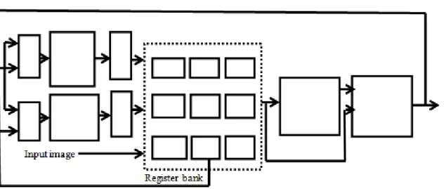
Fig 3.1 VLSI Architecture of DTCMBDM
III.
PROPOSED VLSI
ARCHITECTURE OF DTCMBDM
A pipelined architecture is used to obtain a better timing performance. Also the proposed architecture has low implementation cost since it uses only two line. The pixel values of the image are stored using SRAM. Fig.5 shows block diagram for DTCMBDM. The architecture adopts an adaptive technology and consists of five main blocks: line buffer, register bank (RB), decision-tree-based impulse detector, Conditional filter, and controller. Each of them is described briefly in the following sections.
3.1 Line buffers
In the DTCMBDM three scanning lines are required since it uses a 3×3 mask. Four crossover multipliers are used to realize three scanning lines with two line buffers. Odd-Line Buffer Even-line Buffer are used to store the pixels at odd and even rows, respectively. The line buffer is implemented with a dual-port SRAM (one port for reading out data and other for writing back data concurrently) instead of a series of shift registers to reduce cost and power consumption. If the size of an image is Iw × Ih, the size required for one line buffer is Iw -3 bytes in which 3 represents the number of pixels stored in the register bank.
3.2Register bank
The register bank consists of nine registers. It is used to store the 3 ×3 pixel values of the current mask W. The nine values stored in RB are then used simultaneously by data detector and noise filter for denoising. Once the denoising process for pi,j is completed, the reconstructed pixel value generated by the conditio1nal median filter is outputted and written into the line buffer.
The selection signals of the four multiplexers are all set to 1 or 0 for denoising the odd or the even rows, respectively.
3.3Decision tree based impulse detector
The decision tree based impulse detector is used to detect the noisy pixels in an image. The impulse detector checks each pixel in rows and columns of the image and their relation with the neighboring pixels. It is a complex decision making process. The impulse detector finds solution for the multivariable problem by dividing the complex tasks into simpler problems and finds a unique solution for the problem. For that purpose impulse detector having three modules, Isolation Module, Module, Similarity Module.
3.4 Conditional median filter
Median filter is one of the most suitable filter for the removal of impulse noise in images. It is possible to improve the efficiency of this filter by adding certain conditions. Such a type of filter is called conditional median filter. This can not only reduce the computational complexity but also improve image quality.
3.5 Controller
Controller sends signals to control pipelining and timing statuses of the proposed circuits. It also sends control signals to schedule reading and writing statuses of the data that are stored in register bank or in line buffers. The realization of the controller is based on the concept of finite state machine (FSM). By the controller design, the proposed circuit can automatically receive stream-in data of original images and produce stream-out results of reconstructed images.
IV.
SIMULATION RESULTS
directly. The image is converted to its corresponding pixel values and is fed to the denoising process. The proposed decision tree and conditional median filter based de-noising Method in VLSI is designed using VHDL. MODELSIM is used for the simulation. The simulation results are as follows
Fig 4.1 Original image
Fig 4.2 Noisy image
Fig 4.3 Reconstructed image
V.
CONCLUSION
An efficient non-linear algorithm to remove high density salt and pepper noise using VLSI is proposed.. The conditional median filter not only reduce computation time but also improve the signal to noise ratio. The algorithm removes noise even at higher noise densities and preserves the edge and fine details. The performance of the algorithm is better when compared to the architecture of this type. So this technique can be used directly for medical imaging, scanning techniques, face recognition, license plate recognition etc.
VI.
ACKNOWLEDGEMENT
The author would like to thank Younus college of Engineering, the faculty members of the Department of Electronics and Communication Engineering for the valuable suggestions and facilities provided for completing the task successfully
REFERENCES
[1] P.-Y. Chen, C.-Y. Lien, and H.-M. Chuang, “A Low-Cost VLSI Implementation for Efficient Removal of Impulse Noise,” IEEE Trans. Very Large Scale Integration Systems, vol. 18, no. 3, 2010
[2] R.C. Gonzalez and R.E. Woods, Digital Image Processing. Pearson Education, 2007.
[3] W.K. Pratt, Digital Image Processing.
Wiley-Inter science, 1991. [4] I. Aizenberg and C. Butakoff, “Effective
Impulse Detector Based on Rank-Order Criteria,” IEEE Signal Processing Letters, vol. 11,no. 3, pp. 363-366, Mar. 2004. [5] S.-J. Ko and Y.-H. Lee, “Center Weighted
Median Filters and Their Applications to Image Enhancement,” IEEE Trans. Circuits Systems, vol. 38, no. 9, pp. 984-993, Sept. 1991.
[6] Y. Dong and S. Xu, “A New Directional Weighted Median Filter for Removal of Random-Valued Impulse Noise,” IEEE Signal Processing Letters, vol. 14, no. 3, pp. 193-196, Mar. 2007.
[7] H. Hwang and R.A. Haddad, “Adaptive Median Filters: New Algorithms and Results,” IEEE Trans. Image Processing, vol. 4, no. 4, pp. 499-502,Apr. 1995.
[8] P.E. Ng and K.K. Ma, “A Switching Median Filter with Boundary Discriminative Noise Detection for Extremely Corrupted Images,”IEEE Trans. Image Processing, vol. 15, no. 6, pp. 1506-1516, June 2006. [9] P.-Y. Chen and C.-Y. Lien, “An Efficient
Edge-Preserving Algorithm for Removal of Salt-and- Pepper Noise,” IEEE Signal Processing Letters, vol. 15, pp. 833-836, Dec. 2008.
[10] T. Nodes and N. Gallagher, “Median Filters: Some Modifications and Their Properties,” IEEE Trans. Acoustics, Speech, Signal Processing, vol. ASSP-30, no. 5, pp. 739-746, Oct. 1982.