i
Faculdade de Engenharia da Universidade do Porto
Communications and Cooperation Methodologies
in an Intelligent Wheelchair
Frederico Manuel Santa Clara Barros da Cunha
Dissertation executed under the
Integrated Master in Electrotechnical and Computer Engineering
Major in Automation
Supervisor: Luis Paulo Reis
Co-Supervisor: Rodrigo Braga
ii
v
Abstract
As the number of handicapped people increases worldwide, society is becoming more concerned and alert to their problems. Facing segregation the integration of handicapped people has always been difficult. To augment this separation some of the devices proposed as solutions to handicapped persons, often end up traumatizing them even further.
Intelligent Wheelchairs (IW) are becoming the solution to enable a higher degree of independence for wheelchair users. In addition, IW Projects relevance is increasing, as more projects are launched every year. Currently the focus is on the development of high level control algorithms that may address and integrate the wheelchair’s user in to higher intelligence control levels. However these high level control algorithms often depend and require the communication and interaction between different agents.
This dissertation describes the development of a communication system for an intelligent wheelchair. It starts with the presentation of the underlying concepts and reasons for intelligent wheelchairs. The document continues with the description of the state of the art in the field of intelligent wheelchair as well as middleware solutions that enable inter-agent communications while focusing in a specific, JADE. Moreover a brief assertion is made on the field of safety-critical and its methodologies to facilitate the design of communication systems.
In addition an analysis that enabled the establishment of system’s requirements possible is characterized. The found requirements are presented as well as the systems that are able to address these requirements. Furthermore, it proposes an architecture capable of addressing the found requirements in the field. The implemented architecture and algorithms are then presented and commented.
Finally it goes through and discusses the achieved results in different test scenarios. The achieved results prove the communications’ effectiveness and that it is able to outperform JADE in numerous tests. Moreover, it discusses the implemented system’s applicability, advantages and relevance when applied to intelligent wheelchairs and in a more broader view, to the field of mobile robotics in uncertain and dynamic environments.
vii
Resumo
Devido ao aumento a nível mundial do número de pessoas com deficiências, a sociedade começa a aumentar o seu interesse e a ficar mais alerta em relação aos problemas destas pessoas. Devido às descriminações que sofrem, a integração de pessoas com deficiências sempre foi complicada. Para agravar ainda mais esta descriminação, alguns dos dispositivos propostos como soluções às pessoas com deficiências acabam muitas vezes por as traumatizar ainda mais.
As Cadeiras de Rodas Inteligentes (CRI) começam a tornar-se a solução que dá um maior grau de independência aos utilizadores de cadeiras de rodas. A importância dos projectos de cadeiras de rodas está a aumentar, à medida que mais projectos são lançados todos os anos. Actualmente o foco está no desenvolvimento de algoritmos de controlo de nível mais elevado e que possibilitem a integração do utilizador da cadeira de rodas em níveis mais inteligentes de controlo. No entanto este níveis mais altos de algoritmos de controlo dependem e necessitam normalmente de comunicação e interacção entre diferentes agentes.
Esta dissertação descreve o desenvolvimento de um sistema de comunicação para uma cadeira de rodas inteligente. Ela começa com a apresentação dos conceitos e motivações que estão por detrás das cadeiras de rodas inteligentes. O documento continua com a descrição do estado da arte na área das cadeiras de rodas inteligentes e de soluções de “middleware” que possibilitam a comunicação entre agentes, focando uma mais especificamente, o JADE. Para além do mais, uma breve descrição é feita sobre o campo de sistemas confiáveis e suas metodologias como facilitadores na projecção de sistemas de comunicação.
Uma análise que permitiu possível o estabelecimento de requisitos do sistema, é descrita. Os requisitos encontrados são analisados e uma breve descrição sobre os sistemas capazes de os abordar e dominar é feita. Propõe ainda uma arquitectura capaz de lidar com os requisitos encontrados na área. A arquitectura e os algoritmos do sistema implemento são depois descritos e comentados.
Finalmente passa revista e discute os resultados obtidos usando diferentes cenários de teste. Os resultados alcançados provam a eficácia do sistema de comunicações e que este é capaz de superar o JADE em diversos testes. Discute também a aplicabilidade, as vantagens e
viii
a relevância do sistema implementado, quando aplicado a Cadeiras de Rodas Inteligentes e de uma forma mais geral, à área dos sistemas robóticos móveis em ambientes desconhecidos e dinâmicos.
ix
Acknowledgments
I would like to thank my supervisor, Prof. Dr. Luis Paulo Reis, his guidance, support and my work’s reviews enabling me to develop this work. I also want to thank my co-supervisor Rodrigo Braga for the long conversations we had on this work’s possibilities and for his patience while explaining me every detail in Intellwheels project and integrating my work with it.
I would also like to thank Prof. Dr. Eugénio Costa Oliveira and everyone that work in LIACC for providing me with a stimulating and fun environment.
I am grateful to my closest friends for their support and assistance when reviewing my thesis.
Lastly, and more importantly, I wish to thank my parents, who have given me the freedom to make my own decisions, even when they were not the best ones.
xi
List of Contents
Abstract ... v
Resumo ... vii
Acknowledgments ... ix
List of Contents ... xi
List of Figures ... xv
List of Tables ... xix
Abbreviations and Symbols ... xxi
Chapter 1 ... 1
Introduction ... 1
1.1 – Motivation ... 1
1.2 – Objectives and Work Organization... 2
1.3 – Dissertation Structure ... 2
Chapter 2 ... 5
State of Art ... 5
2.1 – Intelligent Wheelchairs ... 5
2.1.1 – FRIEND II ... 6
2.1.2 – VAHM Intelligent Wheelchair ... 7
2.1.3 – SENA Robot ... 7
2.1.4 – Project’s Summary... 8
2.2 – Communication Systems ... 9
2.2.1 – Universal Plug and Play - UPnP ... 9
2.2.2 – Jini ... 10
2.2.3 – Communication Platforms for Multi-agent Systems - JADE ... 12
2.2.3.1 – JADE Framework ... 13
2.2.4 – Systems’ Summary ... 15
2.3 – Safety-critical Systems ... 16
2.3.1 – Designing Communication Systems ... 18
2.3.1.1 – Transmission Media Classification... 20
2.3.1.2 – Messages’ Threats ... 21
2.3.1.3 – Defensive Measures ... 21
xii
Chapter 3 ... 25
Intellwheels Project ... 25
3.1 – Intellwheels’ Vision and Objectives ... 25
3.2 – Control Architecture ... 26
3.2.1 – Hardware ... 27
3.2.2 – Main Interface or Reactive Agent ... 27
3.2.3 – Intelligence or Cognitive Agent ... 28
3.2.4 – Multimodal Interface or Desire Agent ... 29
3.2.5 – Simulator ... 30
3.3 – Intellwheels’ Additional Agents ... 30
3.4 – Network Usage ... 31
3.5 – Development Status and Considerations ... 32
3.6 – Summary ... 33
Chapter 4 ... 35
Designing a Communication System ... 35
4.1 – Establishing System’s Requirements ... 35
4.1.1 – Safety Requirements ... 36
4.1.1.1 – Step 1, Transmission Media Classification ... 36
4.1.1.2 – Step 2, Safety-Critical Messages ... 37
4.1.1.3 – Step 3, Messages’ Threats ... 37
4.1.1.4 – Step 4, Communications’ Failure Modes ... 37
4.1.1.5 – Step 5, Defensive Measures ... 38
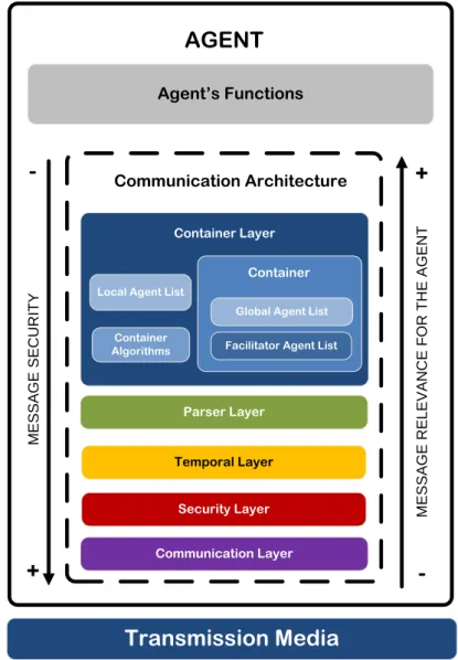
4.1.2 – Functional Requirements ... 39 4.2 – Requirements Analysis ... 39 4.3 – System’s Architecture ... 41 4.3.1 – Local Environment ... 42 4.3.1.1 – Communication Layer ... 43 4.3.1.2 – Security layer ... 43 4.3.1.3 – Temporal Layer ... 43 4.3.1.4 – Parser Layer ... 44 4.3.1.5 – Container Layer ... 44 4.3.1.6 – Agents’ Lists ... 45 4.4 – Summary ... 46
Chapter 5 ... 47
System’s Implementation ... 47 5.1 – Implemented Architecture ... 475.2 – System’s Cooperative Algorithms ... 50
5.2.1 – Local Discovery ... 50 5.2.2 – Container Election ... 51 5.2.3 – LAL’s Creation ... 53 5.2.4 – LAL’s Distribution ... 54 5.2.5 – Platform’s Maintenance ... 55 5.2.6 – Network Discovery ... 56
5.3 – Resulting Message Envelope ... 57
5.4 – Summary ... 58
Chapter 6 ... 59
System’s Integration ... 59 6.1 – Reactive Agent ... 59 6.2 – Cognitive Agent ... 63 6.3 – Door Agent ... 65 6.4 – Medical Agent ... 656.5 – Intellwheels’ New Communications Architecture ... 66
xiii
Chapter 7 ... 69
Experiments ... 69
7.1 – Testing Methodologies and Environment ... 69
7.1.1 – Hardware ... 69 7.1.2 – Software ... 70 7.1.3 – Network ... 70 7.2 – Tests Scenarios ... 71 7.2.1 – System’s overhead ... 71 7.2.2 – System’s Maintenance... 72 7.2.3 – Stress Conditions ... 72 7.2.3.1 – Subtest 1 ... 73 7.2.3.2 – Subtest 2 ... 73 7.2.3.3 – Subtest 3 ... 74
7.2.4 – Agent’s Chain Communications ... 74
7.2.5 – The Book Buyer and Book Seller ... 75
7.2.6 – Intelligent Wheelchair ... 76 7.3 – Tests’ Results ... 77 7.3.1 – System’s Overhead ... 77 7.3.2 – System’s Maintenance... 79 7.3.3 – Stress Conditions ... 80 7.3.3.1 – Subtest 1 ... 80 7.3.3.2 – Subtest 2 ... 81 7.3.3.3 – Subtest 3 ... 82
7.3.4 – Agent’s Chain Communications ... 82
7.3.5 – The Book Buyer and Book Seller ... 84
7.3.6 – Intelligent Wheelchair ... 85
7.4 – Summary ... 88
Chapter 8 ... 89
Conclusions and Validation ... 89
8.1 – Main Results... 89 8.2 – Achieved Objectives ... 89 8.3 – Work’s Assessment... 90 8.4 – Future Work ... 91 References ... 93 ANNEXES ... 97 A – EN 50159 Support Tables ... 98
B – Code for JADE’s “Pass the secret” Agent ... 100
C – Code for JADE’s “Book Buyer” Agent ... 102
xv
List of Figures
Figure 2.1 - Search results for the topic "Intelligent Wheelchair". ... 5
Figure 2.2 - UPnP device architecture [23]. ... 10
Figure 2.3 - Jini’s interaction model. ... 11
Figure 2.4 - Services provided by a FIPA platform [22]. Blue - normative services. Green – optional services. ... 12
Figure 2.5 - JADE’s functional architecture [34]. ... 14
Figure 2.6 - Relationship between Fault, Error and Failure that can lead to a dangerous state in the system... 16
Figure 2.7 - Process that leads to the determination of a system's SIL, described in IEC 61508 [41]. ... 18
Figure 2.8 - Communication System's architecture recommended in EN 50159. To the left the architecture when using closed transmission systems and specified by the standard's part 1. To the right the architecture specified in the standard's part 2. ... 19
Figure 2.9 - Communication System Safety Analysis Process. ... 20
Figure 3.1 – Intellwheels multilevel control architecture, from [2]. ... 26
Figure 3.2 - Intellwheels' software architecture, adapted from [2]. ... 26
Figure 3.3 - Main Interface. ... 27
Figure 3.4 - Intellwheels' path planner. ... 29
Figure 3.5 - Multimodal Interface, from [5]. ... 29
Figure 3.6 - Simulator's viewer displaying the 3D vision, from [7]. ... 30
Figure 3.7 - Door's control algorithm, from [11]. ... 31
Figure 3.8 - Intellwheels network usage, from [7]. ... 32
Figure 4.1 - Proposed layered architecture. Adapted from [58][59]. ... 42
Figure 4.2 - Lists' distribution through the system's agents. Red - Container distributes the list. Green - agent confirms list’s reception. ... 45
xvi
Figure 5.1 - Developed Delphi components. ... 47
Figure 5.2 - Thread-safe FIFO buffer. ... 48
Figure 5.3 – Designed Layer Template. ... 48
Figure 5.4 - Communication components and their functions. ... 49
Figure 5.5 - XML message transmitted between layers. ... 50
Figure 5.6 - Discovery algorithm. ... 51
Figure 5.7 - Container election interaction UML diagram. ... 52
Figure 5.8 - Protocol used by the Container to known an agent's info. ... 53
Figure 5.9 - Protocol used by a new agent to announce its presence. ... 54
Figure 5.10 - Protocol used by the Container to inform a LAL update. ... 54
Figure 5.11 - Protocol used by the Container to confirm that is still alive and to check the agents. ... 55
Figure 5.12 - Protocol used by a Container to discover network Containers. ... 56
Figure 5.13 - Proposed system's resulting message envelope [58][59]. ... 57
Figure 6.1 - Wheelchair's Control agent name. ... 59
Figure 6.2 - Control agent after the communication's system integration. ... 60
Figure 6.3 - UML sequence diagram for the interaction between the Control and Planner agents. ... 61
Figure 6.4 - UML sequence diagram for the interaction between Controller and Medical Agent. ... 62
Figure 6.5 - Reactive agent after the new communication's system integration. ... 63
Figure 6.6 - UML sequence diagram for the cognitive agent’s request to a door agent to provide and update its position. ... 64
Figure 6.7 - UML sequence diagram for the cognitive agent’s request for a door agent to open in a plan... 64
Figure 6.8 - Intellwheels' Medical agent. ... 65
Figure 6.9 - Current Intellwheels agent's architecture. Red – represents the proposed communication system. ... 66
Figure 6.10 - Intellwheels global agent architecture. ... 67
Figure 7.1 - Interaction between applications. X represents the cycle’s number. ... 73
Figure 7.2 - Interaction between the agents. X is an integer number used as a control mechanism for message differentiation, and the numbers in between round brackets the interaction sequence. ... 74
xvii
Figure 7.4 - Book buyer and book seller interaction example. The numbers in between
round brackets represent the message's order. ... 76 Figure 7.5 - Hospital map and node tree. Red, task's initial and final points. Green, IW
start point. ... 77 Figure 7.6 - Results achieved for the time needed to discover the applications and elect a
container. ... 77 Figure 7.7 - Results achieved for the time needed for the container to collect the
applications' information. ... 78 Figure 7.8 - Results achieved for the time needed to distribute the LAL. ... 78 Figure 7.9 - Results achieved for the time needed to inform all applications of a new
platform round... 79 Figure 7.10 - Results achieved to elect a new container after the initial's failure. ... 80 Figure 7.11 – Messages’ maximum size limit for UDP and TCP. In cyan the messages at OSI
level 3. In magenta the messages treated by the proposed layers. The yellow line establishes the size limit. ... 81 Figure 7.12 - Results achieved during subtest 3. The grey color represents the time
needed to transmit UDP messages. The green color represents the time needed to transmit TCP messages. ... 82 Figure 7.13 - Results achieved in the test 4 while using JADE as the communications
platform. ... 83 Figure 7.14 - Results achieved in test4 using the proposed platform and algorithms as
communications enabler. Green represents the average time measured in the test. .... 83 Figure 7.15 - Results achieved in test 5 using the JADE system. Blue represents the
average time measured. ... 84 Figure 7.16 - Results achieved in test 5 using the proposed system. Green represents the
average time measured. ... 84 Figure 7.17 - a) Reactive agent's communications console. b) Cognitive agent's
communication console and Plan tab. ... 86 Figure 7.18 - Reactive agent's action list. ... 86 Figure 7.19 - 3D Viewer's images. The figures present the IW moving from the node 19,
turning to the left and stopping at node 3. ... 87 Figure 7.20 - Paths traveled by the IW. ... 87
xix
List of Tables
Table 2.1 - Project's communication system's comparison. ... 8 Table 2.2 - Comparison between the described communication systems. ... 15 Table 2.3 - SIL levels and their required acceptable probability of failure, defined in the
IEC 61508 standard [41]. ... 17 Table 2.4 - Defences applicable to applicable to each threat. From the EN 50159-2 Annex
C. ... 22 Table A.1 - Transmission system classification, from the EN 50159–2 Annex C. ... 98 Table A.2 - Threats significance according to the transmission system used, from the EN
50159–2 Annex C. (++) represents a exist threat that requires strong countermeasures. (+) represents an existent threat that requires weak
countermeasures. (-) represents a negligible threat. ... 99 Table A.3 - Defences applicable to the threats, from the EN 50159-2 Annex C. ... 99
xxi
Abbreviations and Symbols
List of abbreviations
ACL Agent Communication Language AID Agent Identifier
AMS Agent Management System COTS Commercial Off-The-Shelf
CORBA Common Object Request Broker Architecture EUA Equipment Under Control
FAL Facilitator Agent List
FEUP Faculdade de Engenharia da Universidade do Porto FIFO First In First Out
FIPA Foundation for Intelligent Physical Agents FMEA Failure Mode Effects Analysis
FMECA Failure Mode Effects and Criticality Analysis FTA Fault Tree Analysis
GAL Global Agent List GUI Graphical User Interface GUID Globally Unique Identifier IW Intelligent Wheelchair
JRMI Java Remote Method Invocation LAL Local Agent List
LAN Local Area Network
LIACC Artificial Intelligence and Computer Science Laboratory
LUS Lookup Service
MAS Multi-Agent System NTP Network Time Protocol PHA Primary Hazards Analysis PTP Precision Time Protocol SIL Safety Integrity Level
xxii SOA Service-oriented Architecture TCP Transmission Control Protocol UDP User Datagram Protocol XML Extensible Markup Language
1
Chapter 1
Introduction
In this chapter a small introduction to the Intellwheels project is made, by presenting the motivational background that has lead to its creation. Additionally this work’s objectives and work organization will be presented as well as a brief resume for this document’s structure and organization.
1.1 – Motivation
According to data provided by World Health Organization, an estimated 10% of the world’s population live with some form of disability or impairment, around the world [1]. From these an estimated 20% and rising, have physical disabilities. The causes that lead to these impairments are often indentified as the population’s aging due to the increase in life’s expectancy, environment degradation, sub nutrition, congenital health diseases, accidents, wars and birth defects [2][3].
The increase in the public’s awareness to these problems has attracted the attention of different health care organizations, enterprises and universities. These, interested in resolving some of the issues for providing to the users higher independence and mobility, have been launching projects and initiatives that aim at developing new services, assistive technologies as well as user interfaces. Although the common solution for people with reduced mobility is an electric wheelchair, those with higher handicap levels are not able or have difficulties using it [4].
Alongside with other projects, an intelligent wheelchair prototype and development platform [2] is currently ongoing in the Artificial Intelligence and Computer Science Laboratory (LIACC) at the Faculdade de Engenharia da Universidade do Porto (FEUP). This project strives to achieve a modular architecture that can be installed in any commercially available electric wheelchair and by any user. It is in an advanced development stage, with 3 wheelchairs already installed with the project’s hardware and software architecture. By using
2 Introduction
the available software, the user is already able to introduce high level orders into the system, either by vocal commands, head or facial movements or the commonly used joysticks and keyboards [5][6]. Two driving modes are available to the user, manual and automatic. When manual is chosen, an assistance feature can be activated. This activates the control system that aids the user by detecting and automatically avoiding obstacles in the wheelchair’s path.
The automatic system implements simple movements as straight forward drive, turning and “go to” functions. A complex and automatic navigational system is also available, using trajectory planning algorithms [3].
Furthermore, a realistic simulation tool [7][8] was developed based on the Ciber-Rato simulator [9][10]. The robotic agents’ control systems and functionalities can be tested realistically in the simulator by using mixed realities, without the need for extensive hardware configuration [11].
Despite the project’s advanced development status, there are still issues that need to be tackled. One of these is the wheelchair’s interaction with humans and other intelligent wheelchairs. As a robotic agent, the intelligent wheelchair does not live isolated in the world. And in order for it to be an efficient and useful assistive robot, it needs to communicate and cooperate with the environment it is in. However, as these robots provide services while interacting with humans, the communication and cooperative methods they use must do so in a safe and secure manner.
1.2 – Objectives and Work Organization
Based on the Intellwheels’ operating architecture, this work’s main objectives were defined as the following:
To study the Intellwheels’ architecture in detail and identify the main requirements and constraints to the development and usage of a communication system in the projects’ context;
Design and develop a high-level communication system that can address the identified requirements;
Integrate the developed communication and cooperation system with the existing Intellwheels modules.
1.3 – Dissertation Structure
This dissertation is organized in 8 chapters. Each chapter starts with a small introductory text describing the chapter’s intent and to the exception of the present one, ends with a brief summary. The current introduction chapter presents the background motivation for the Intellwheels project and for intelligent wheelchairs in general. It also enumerates the proposed work’s objectives and describes the work's organization.
1.3 – Dissertation Structure 3
The second chapter offers a view on the state-of-art related with intelligent wheelchairs, focusing it in the development, implementation and usage of communication systems as well as cooperative systems in this field. Furthermore, it presents the concepts and state-of-art related with the fields of safety-critical, multi-agent systems and cooperative systems.
In the third chapter, the Intellwheels project is presented and its architecture described. The present development stage is also discussed while contextualizing this work’s relevance within the project.
The fourth chapter describes the processes that led to the new communication system. The system’s functional and safety requirements are enumerated and contextualized in the project’s field. The developed system is also described as well as the resulting message’s envelope.
The fifth chapter provides a description on the cooperative behaviors implemented with the system. These range from the algorithms used to organized and maintain the platform to those used to execute tasks.
The sixth chapter provides an insight into the modifications performed to the Intellwhells’ software modules and the interaction models implemented. Finally, the project’s current architecture with the new communication system is presented.
In the seventh chapter, the tests performed are characterized. The methodologies used to analyze data along with the testing environment will be described in detail. In addition, the implemented software used in the tests is described. Furthermore the tests’ results are presented along with their analysis.
The eighth chapter concludes on the results achieved in the tests comparing them to the proposed objectives for this thesis. Furthermore, considerations are made on this work’s future modules.
5
Chapter 2
State of Art
This chapter’s intent is to introduce the different scientific themes and trends relevant to this thesis and the developed work that are related to the fields of robotics and artificial intelligence. The chapter is divided into 3 sections, each one presenting the state of art, works and concepts related to a specific field: intelligent wheelchairs, communication systems and safety critical systems.
2.1 – Intelligent Wheelchairs
Numerous Intelligent Wheelchair (IW) related projects have been announced, and are currently under development in the last years. Figure 2.1 shows the number of publications that exist related to intelligent or smart wheelchairs in the Computer Science field and that are referenced in 4 search engines.
Figure 2.1 - Search results for the topic "Intelligent Wheelchair".
0
100
200
300
400
Scholar
ISI
Science
Direct
SCOPUS
6 State of Art
The increase study of this field, led to a globally accepted view of the main functional requirements for such systems [12][13]. The main functions of an IW can be categorized as the following:
Interaction with the user – this includes hand based control (such as joystick, keyboard, mouse, touch screen), voice based control, vision based control and other sensor based control;
Autonomous navigation – it must implement safe, flexible and robust obstacle avoidance;
Communication systems – it enables interaction with other devices like other IWs, intelligent robots, automatic doors as well as remotely operated control software for medical staff.
Although many IW projects exist, the majority tends to concentrate their efforts in the interface with the user or in the navigational system. The communication system used is rarely described and scarcely treated as an important and vital piece of an Intelligent Wheelchair.
A common solution seen for the communication system is the use of CORBA [14] based systems, or other technologies that by using memory sharing techniques enable system communication [15] [16].
The following projects’ descriptions are the result of a literary review to IW projects, focused on the design, implementation and usage of communication systems.
2.1.1 – FRIEND II
FRIEND project was developed at the University of Bremen’s Institute of Automation (IAT). The project’s main objective is to assist handicapped users with upper-limb impairments and locomotive issues [17].
The system’s first generation was called FRIEND and was composed of an electric wheelchair and a robot arm mounted on top of the wheelchair. Both systems were controlled by a software architecture that implemented a complex layered control system. The user was able to interact with the system by using vocal commands that were interpreted by the control system and transformed into executable orders.
In 2005 the system evolved to a second generation, FRIEND II that besides extending the hardware that the system was able to use, it implemented a new multi-layer software framework [15]. Its purpose was to be able to use and interact with smart devices present in a home environment through the adaptation or generation of new operating sequences. These operating sequences would then be used to automatically control the system.
The framework was divided into 3 parts: a hardware layer, a skill layer and a sequencer layer, and made possible the execution of several skills simultaneously.
2.1 – Intelligent Wheelchairs 7
To enable this, communications between all the system’s modules were redesigned in order to use CORBA and its specific mechanisms. By implementing this communication method the system’s modularity and expansibility was enhanced while requiring minimal software reimplementation. Moreover the use of CORBA enabled the encapsulation of the communications capabilities and an enhanced data management.
2.1.2 – VAHM Intelligent Wheelchair
One of the earliest references to the Vehicule Autonome pour Handicapés Moteurs (VAHM) project dates from 1998 [18] and its focus was set on the human-machine interface as a path towards efficient electric wheelchair’s control.
By 2000 a simulator module’s project was initiated and motivated by the need to evaluate the developed system in collaboration with real disabled patients [19].
In 2002 the project’s control architecture evolved into a structure that would take into account the surrounding environment [16]. The new control architecture was divided into three essential parts: planning, behaviour and coordination. These were implemented through three agent classes:
Behaviour agents – supplied low level control information;
Cognitive agents – responsible for collecting the data supplied by the behaviour agents and interpret it. They would then create a view of the surrounding environment;
Environment agents – responsible for the wheelchair’s interaction with the outside environment.
These agents would communicate and interact with each other by making use of a multi-agent system that used shared memory as the communications facilitator.
The use of a multi-agent system to manage communications in a wheelchair environment brought numerous advantages to the system [16]. One of them was system’s robustness. By implementing the above mentioned agents, it became possible to implement a redundant control system. Whenever an agent stopped working due to either sensor’s failure or to functional problems, it would be immediately replaced by a new one.
2.1.3 – SENA Robot
The SENA robot is currently under development at University of Malaga in Spain. It is one of the few IW projects that address the communication system.
Similarly to the Intellwheels project, it is based on a commercially available electric wheelchair. Equipped with several sensors as well as a camera mounted on top, it is controlled by a computer through a USB connection to microcontroller that acts on the systems’ motors.
8 State of Art
Its control architecture was initially based on a 3 layers structure called ACHRIN [20]. These layers were called functional, deliberative and the execution and control. Together they facilitated a person’s integration into any of the wheelchair’s robotic operations including plan’s deliberation and execution.
The system latter evolved into a multi-agent based system, called MARCA, as ACHRIN began to exhibit some shortcomings [21]. Amongst these were:
The rigid client-server communication model used; System’s redundancy had to be manually implemented;
A Multi-Agent System (MAS) methodology was chosen due to the MAS’s maturity, robustness, scalability as well as the autonomy and rational behaviour that they confer on to the agents.
The previous system’s implementations were adapted to the newer through the use of agents. To facilitate human interaction with the system, an agent template was made. This served as the base for all the agent implementations, and was named Common Agent Structure (CAS).
The inter-agent communication was designed to use messages’ passing and their format was based on the FIPA-ACL standard [22]. Additionally a learning system was embedded into the agents’ state machine through CAS, and implemented a reward system. If an agent was able to perform a skill it would receive a reward that in turn affected the system’s learning capabilities.
2.1.4 – Project’s Summary
Taking into account the previous descriptions a comparison can be made, between the three projects described, through their properties, as seen in Table 2.1.
Table 2.1 - Project's communication system's comparison.
FRIEND II VAHM SENA
Control
architecture Layered Agent based Agent based Communication
technology / method
CORBA Memory sharing Messages
Communication
Language Not referenced Not referenced
FIPA-ACL standard based Software learning
ability Not referenced Yes Yes
2.2 – Communication Systems 9 sharing, interaction with environment’s devices sharing, agent communication collaboration and competition
As seen in the table, the most significant contribution is the one from the SENA project that describes in detail its communication system. Moreover it proposes the usage of an agent template that facilitates the agent’s learning ability as well as inter-agent task collaboration and competition. Furthermore, it implements a standardized communication language combined with a message-oriented communication paradigm.
All these characteristics can be perceived as desirable in any communication system when used in mobile robotics’ environment.
2.2 – Communication Systems
The past decade has brought tremendous advances in communications technology and models. One of these indicators is the development and generalized usage of wireless communication systems and the use of dynamic and mobile networks as opposed to older and stricter communication models. Combined, they allow users to access to the Internet from virtually any place in the world. However mobility also means getting away from configured and known environments and to enter into foreign networks with unknown infrastructures. This environmental uncertainty leads to an inefficient usage of the available resources and services that a network or community can offer.
In an attempt to contradict these new problems in the last few years a large number of initiatives have been launched, backed up by different industries leaders. Using standardized modelling languages and based on peer-to-peer models, they aim at providing high level services’ discovery and integration as well as automatic services configuration. Moreover, some of these frameworks provide solutions that combine concepts from artificial intelligence and speech act theory thus implementing the agent’s paradigm.
The following subsections present some of these service discovery frameworks that tackle the known issues in different ways.
2.2.1 – Universal Plug and Play - UPnP
Maintained and promoted by the UPnP Forum [23], Universal Plug and Play (UPnP) was initially developed by Microsoft. UPnP was designed to implement a set of networking protocols that when combined enable automatic discovery and connectivity between multiple device’s classes. It is used in various scenarios that range from simple media servers to routers and gateways, enabling the automatic and seamless configuration of the devices.
10 State of Art
UPnP’s architecture is based on TCP/IP, web technologies and XML [24] and it is structured as shown in Figure 2.2. The use of open technologies allows it to be implemented on any operating system and to use any type of physical network.
Figure 2.2 - UPnP device architecture [23].
The standard is based on the interaction between control nodes and devices. Whenever a device enters a network, the Simple Service Discovery Protocol (SSDP) [25] will advertise its existence to the control nodes. Similarly when a control node enters a new network it will search for devices in the network.
In both cases the messages exchanged between a control node and a device, only allow basic identification information to be known as well as a URL for further information. This information is stored in a XML file and characterizes a device’s services, capabilities and properties. Whenever information or a service is required from the device, the XML file is retrieved and the service is subscribed by the control node using a SOAP message.
When new information is available, the device sends an event message, using GENA, to the service’s subscriber with the updated device’s state and data. In order to maintain all control points equally synchronized with updates, it implements a multicast event notification system.
2.2.2 – Jini
Jini, also known as Apache River, was introduced in 1998 by Sun Microsystems [26]. It is written and based on JAVA technology and uses Java object serialization and JRMI to move objects and to invoke remote methods [27]. Its main advantage is its unified view of resources, that abstracts the manner in that the service is located and how it is implemented and the possibility to implement federation models. Its architecture is based on the interaction between 3 entities [28][29]:
IP
UDP
TCP
SSDP
Multicast
Events
SOAP
HTTP
GENA
UPnP Device Architecture
UPnP Forum
UPnP Vendor
2.2 – Communication Systems 11
Lookup Service (LUS) – it is responsible for registering and facilitating the services’ object and attributes that are available in the network. The service’s object is actually a proxy that decides where the service is performed and can be implemented as a RMI stub. The LUS is implemented as a distributed system;
Service provider – it is responsible for providing a service or information to clients. When it is connected to a network, automatically attempts to discover a LUS to register its service;
Client – it is the services’ consumer. When connected to a network it will try to find the network’s LUS and then requests the desired services. After obtaining the service’s description it interacts directly with the service.
This interaction can be seen in Figure 2.3.
Figure 2.3 - Jini’s interaction model.
The interaction is backed up by the use of a discovery protocol. This protocol makes use of multicast messages to enable the discovery of all LUS in the network and is used by both the clients and services’ providers.
In addition to the discovery protocol, Jini makes use of two object protocols named Join and Lookup. The Join protocol enables a service’s registration with the LUS. It provides the object that contains the service’s interface and methods. The Lookup protocol is used by the client when querying a LUS for a specific service’s location. The actual execution of the query can be performed by a different entity.
Besides the described methods for interacting with services, it is also possible to setup a federation model between different Jini service providers and clients.
Service
Provider (Consumer)Client
JINI Lookup Service
(1) Service discovers LUS and registers its
service
(2) Client discovers LUS and requests the desired Service
(4) Client uses proxy and contacts
Jini service (3) Client receives Java
proxy for the Service
12 State of Art
2.2.3 – Communication Platforms for Multi-agent Systems - JADE
Multi-agent Systems (MAS) is a subfield of Artificial Intelligence that in combination with speech act theory, provide the principles for the construction of complex systems [30]. These systems often involve multiple entities that communicate and collaborate with each other to perform a set of tasks. These entities are called agents.
An agent can be considered as a computational system that is autonomous, proactive and social [31]. A robot is also an agent but with a physical body with goals, interests, actions and situated in an environment [32].
The application of MAS in complex systems has brought many advantages identifiable as: Parallel computation;
Scalability; Modularity; Robustness;
Cost effectiveness.
To assist in the development of agents and agent based systems, in 1996 the Foundation for Intelligent Physical Agents (FIPA) [22] was created. The standard currently addresses different categories in agent development, although the most important is agent communications. To support it the FIPA Agent Communication Language, FIPA-ACL [22] and the FIPA-SL [22] language were developed. By using the FIPA-ACL standard the message’s body can be filled with the main information.
In addition the standard also identifies and characterizes the MAS requirements for agent support. It defines the implementation of methods that enable higher agent’s reasoning and perception as well as the services. These services represent the solutions for the requirements that must be provided in a MAS, as seen in Figure 2.4.
Figure 2.4 - Services provided by a FIPA platform [22]. Blue - normative services. Green – optional services.
Agent Life Cycle Management Ontology Service Message Transport Service White Pages Yellow Pages Agent Software Integration Human Agent Integration
2.2 – Communication Systems 13
Various MAS frameworks and platforms exist. Some of the most known are: DIET Agents; FIPA-OS; Cougaar; kSACI; Jadex; DESIRE; IMPACT.
However for this thesis only the JADE Framework [33] will be described in detail as it is based in the FIPA standard and developed by the TIILAB, one of the initial promoters of FIPA.
2.2.3.1 – JADE Framework
Java Agent DEvelopment Framework (JADE) [33], was designed to be a middleware for multi-agents applications. It is developed by JADE Team and supervised by the JADE Board, a group with the following members: TILAB, Motorola, France Telecom, Whitestein Technologies AG and Profactor [34].
It is an open source software project distributed by TILAB and developed in Java that follows the FIPA standard and is based in the principles of interoperability between agents and platforms, uniformity and portability [30]. it can be used in a variety of hardware platforms and operating systems that range from the common desktop to mobile Java platforms and always independent of the network configuration used. It is easy to use as it abstracts the implemented functions and the system’s configuration through an API.
JADE was designed to make use of a set of components that include the following:
Agent Management System (AMS) – it is responsible for the identification of the system’s agents as well as their states, acting as a white pages service;
Container – a JADE run-time instance responsible for managing the agents’ life cycle and update the agent’s state. It serves as a host for the system’s agents;
Main-Container – the initial instance of the JADE run-time, responsible for managing the platform including the connections made to additional containers.
Whenever a JADE Framework is used, the set of all the existing containers is called a Platform [30]. A Platform can be implemented using different system configurations and JADE’s connection capabilities. It is possible to implement a Platform using: only the Main-Container, a Main-Container and an additional local Container and lastly a Main-Container and a Container in a remote machine. The connections to containers are stored in a list within the Main-Container named Container Table (CT) [34]. When a connection between Containers is established with only one platform, the IMTP protocol is used. This protocol is an adaptation of the JRMI [34]. JADE’s functional architecture can be seen in Figure 2.5.
14 State of Art
Figure 2.5 - JADE’s functional architecture [34].
Moreover it is possible to implement a connection between platforms, and for these cases the IIOP protocol is used. No matter the platform’s container connections, the system’s complexity is hidden from the agents as they can only perceive the existence of a platform and its services.
However JADE’s inter-platform connections are not limited to the default IIOP protocol. It is also possible to use federation models. The federation communication is mainly used to synchronize the different Directory Facilitators and to configure a system that tolerates Main-Container failures as long as a relational database is used [34].
To assist in the agent’s development the following agents are available to the user [34]: A JAVA class named Agent is available that serves as a agent template. Through the
configuration of a setup() method, it is possible for the user to programme the agent’s behaviours. Communications are available through a agent’s messages queue that when altered generates an event for the agent to treat the message;
Remote Monitoring Agent (RMA) – it graphically controls the platform. It is only possible to have one RMA for each Container;
Dummy Agent – it monitors and allows message debugging. In addition it is possible to use it to send fully customized message;
Sniffer Agent – it is able to intercept a message sent by an agent and its visualization in a graphical manner similar to a UML diagram. To discover the agents present in the platform it taps in to the AMS;
Directory Facilitator – it is JADE’s implementation of the yellow pages service specified by FIPA. It allows the invocation of different services as service’s query or register;
Agent Management System – provides information on the agent’s existence as well as their state. As mentioned above its functions are those of a white pages server;
CONTAINER #1
LADT
GADT
MAIN-CONTAINER
LADT
GADT
CT
IMTP
DF
AMS
RMA
AMS
AMS
CONTAINER #2
LADT
GADT
AGENT
#3
AGENT
#4
AGENT
#1
AGENT
#2
IMTP
2.2 – Communication Systems 15
Introspector Agent – allows the user to monitor the agent’s life cycle, the messages’ queue as well as its behaviour queue.
All agent communications are performed using the FIPA-ACL language in an asynchronous way and the FIPA performative are used in the messages. FIPA-SL can be used as the content’s language but JADE’s supports every messaging standard that Java implements as well as Java’s object serialization methods.
To assist in the agent’s mobility, JADE’s internal message queue was designed to implement a tolerant behaviour. When a message’s destination is not present or its state does not allow the message’s treatment, the message is set to the AMS and stored there [34]. When the message’s destination becomes once more available the message is delivered to him [34].
2.2.4 – Systems’ Summary
Taking into account the previous descriptions a comparison can be made between all the systems’ through their properties, as seen in Table 2.2.
Table 2.2 - Comparison between the described communication systems.
UPnP Jini JADE
Service Invocation XML data Java Code and
Objects Java
Directory style N/A Distributed Centralized and Distributed Automatic
Discovery Yes Yes Yes
Services’ Query Yes Yes Yes
Services’
Announcement Yes Yes Yes
Network
Architecture Mesh Mesh
Tree, Ring, Distributed Federation
models No Yes Yes
16 State of Art
2.3 – Safety-critical Systems
Oxford Dictionary defines safety as ”the state of being safe” and “the state of not being dangerous” [35]. Another definition can be “dependability with respect to the non-occurrence of dangerous failures” [36]. The latter definition is related to the field of System’s Engineering and is often used in that context. Taking this definition of safety into account, a Safety-critical System can be interpreted as one that, if a failure occurs it might cause damage on persons, property or the environment [36][37]. Associated to this type of systems is also the concept of reliability, as the “dependability with respect to the continuity of service” and “measure of continuous correct service delivery” [38]. Taking the presented definitions into consideration, we can perceive a safety-critical system as a collection of hardware & software, correlated, that must deliver a continuous and correct service, at the cost of causing damages, either in persons, properties or even the environment.
The usage of this term to describe specific systems started in the early 1980’s, with the development of safety relays. By 1990’s safety logic systems were being used, and followed soon after by safety buses [36][39]. They are currently becoming increasingly important in the field of robotics, applied to aerospace and medical rehabilitation. These robotic agents are often designed to operate at remote locations, hazardous environments or to interact with humans and thus require the ability to circumvent failures without direct human intervention. An application of these systems to the aerospace industry, is the Boeing’s 777 flight control system [40] implemented as a triple redundant control system.
Opposed to the definition of a safe state, is the definition of a non-safe system and the cycle that leads to a system’s failure state. The IEC 61508 standard [41] presents three concepts that address this, Fault, Error and Failure, and establishes their relationship as represented in Figure 2.6.
Figure 2.6 - Relationship between Fault, Error and Failure that can lead to a dangerous state in the system.
FAULT
system impaiment; hidden; indetectable; related to the system’s design time;ERROR
detectable; quantifiable; can be controlled;FAILURE
system does not provide service; caused by an error; if not controlled leads to if activated can lead to2.3 – Safety-critical Systems 17
It is only possible to reduce a system’s risk, and thus preventing errors, by following strict development methodologies and system analysis (PHA, FTA, as top-down methodologies and FMEA, FMECA [42], as bottom-up methodologies), and by establishing a Safety Life Cycle, described in the IEC 61508 [41] and IEC 60812 [42] standards. Even after following these methodologies, the system’s risk is only reduced to an acceptable level [43]. The MGA Exoskeleton [44] used for shoulder therapy and rehabilitation is an example, amongst many others, of a robotic project that followed safety-critical methodologies to implement a fail-safe system. The Bremen Autonomous Wheelchair [45] an electric wheelchair, is another project that used the above mentioned methods, specifically fault trees, to analyse the development of a safety layer.
To facilitate the treatment of the different systems’ safety requirements, during development, the Safety Integrity Levels (SIL) were standardized [36][39][46][47][48][49]. These are related with the techniques used to reduce a system’s risk and define the required failure intervals. They must be defined as one out of four levels, presented in Table 2.3 with the required probabilities’ of failure intervals. SIL 1, for the level with the lowest risk, until SIL 4, the one with the highest risk associated and with the highest level of system constrains to development [36]. These levels also represent the degree of confidence that can be entrusted onto a system and its’ functions during their Life Cycle [46][47] and can be quantifiable by following the process seen in Figure 2.7.
Table 2.3 - SIL levels and their required acceptable probability of failure, defined in the IEC 61508 standard [41].
Safety Integrity Level
Low Demand mode of operation (average probability of failure to
perform its design function on demand)
High
demand/continuous mode of operation
(probability of a dangerous failure per
hour) 4 ≥ 10-5 to < 10-4 ≥ 10-9 to < 10-8 3 ≥ 10-4 to < 10-3 ≥ 10-8 to < 10-7 2 ≥ 10-3 to < 10-2 ≥ 10-7 to < 10-6 1 ≥ 10-2 to < 10-1 ≥ 10-6 to < 10-5
18 State of Art
Figure 2.7 - Process that leads to the determination of a system's SIL, described in IEC 61508 [41].
2.3.1 – Designing Communication Systems
When analysing a system, the communication system must also be considered. The IEC 61508-2 addresses this system’s part, and recommends the use of other normative references specific to the system’s field.
A solution often seen is the use of the EN 50159 parts 1 [46] and 2 [47]. The standard’s Part 1 refers to the application of this layer to closed transmission systems and Part 2 to open transmission systems, as seen in Figure 2.8. Together they address the design and development of communication systems for railway systems. Despite their lack of reference to the OSI reference model, their use in other fields is possible as they do not set specific safety requirements. Instead they define the methods for designing and implementing a safety layer on top of the system’s transmission layer. This safety layer’s function is to implement the communication’s defensive measures.
Desired
System's
Risk
Identify a dangerous situation in the system; Quantify the acceptable system's risk;Actual
System's
Risk
Determine the dangerous situation frequency, Fnp; Determine the analised dangerous situation concequence, C; System' s Risk = Fnp* C;Risk
reduction
Determine if it is necessary to perform a risk a reduction, and quantify the minimum reduction,∆R;
System's
protection
failure rate
Determine the maximum failure probability in "low demand"
mode for the system's protection, PFDAVG= Ft/ Fnp= ∆R;
System's
SIL
Cross-reference the values with the apropriated tables;
2.3 – Safety-critical Systems 19
Figure 2.8 - Communication System's architecture recommended in EN 50159. To the left the architecture when using closed transmission systems and specified by the standard's part 1. To the right
the architecture specified in the standard's part 2.
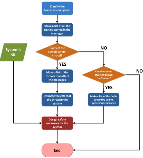
To assist in the design of these measures, the procedure seen in Figure 2.9 is used. The method is based on the classification of the system’s transmission media and, the listing of transmitted signals and their criticality analysis. If a signal or message is considered critical, and it is probable for an error to occur with the signals transmission, then the message must be protected. In these cases, safety measures must be put in to use according to the failure severity. The presented procedure as well as the safety measures applicable to a communication system, is described in further detail in [39] as well as in EN 50159–2 [47].
Application or
Equipment
Safety-Layer
Closed
Transmission
Functions
Application or
Equipment
Safety-Layer
Open
Transmission
Functions
Closed
Transmission
System
Open
Transmission
System
EN
5
0
1
5
9
-1
EN
5
0
1
5
9
-2
20 State of Art
Figure 2.9 - Communication System Safety Analysis Process.
2.3.1.1 – Transmission Media Classification
The first step towards the design and usage of a safe communication system is the classification of the system’s transmission media. Only after characterizing the used media, can the system’s threats be correctly identified, as these may depend on the media and the control exercised over it.
According to the EN 50159-2 standard [47], the transmission systems are classified and separated into classes ranging from class 1 to class 7. Class 1 is only used for transmission systems that can be fully characterized and whose properties do not change during the system’s life cycle. Class 7 is often used for systems that can’t be characterized and whose issues are not fully known. These classifications are represented in Table A.1, along with their respective characteristics and examples, within this thesis’ ANNEX A and in the EN 50159–2 Annex C [47].
Make a list of all the signals carried in the
messages
Is any of the signals
safety-critical?
Make a list of the threats that affect
the messages
Estimate the effect of the threat in the
system
Can the comm. stystem disturb the System?
Make a list of the faults caused by comm. System’s disturbancy
End
Design safety measures for the
system
System’s
SIL
YES
YES
NO
NO
Classify the transmission system2.3 – Safety-critical Systems 21
2.3.1.2 – Messages’ Threats
To prevent communication’s errors, a correct identification of threats to the communication system must be made. The EN 50159-2 standard defines a threat as “a potential violation of safety including access protection of a communication”[47]. It standardizes the threats as the following set:
Repetition – results in the error of receiving multiple times the same message; Deletion – results in the message’s removal from the media;
Insertion – results in the implanting an additional message into the media;
Resequence – results in the alteration of the message’s order in the set of messages; Corruption- results in the message’s data corruption;
Delay – results in the message’s reception at a later time than it was intended ; Masquerade – results in the interpretation of a non-authentic message that was
designed to appear to be authentic.
To assist in the threats identification the transmission system used must be taken into consideration. The threats significance depends on the transmission system used and on the occurrence of hazardous events.
Some of the factors related to the transmission system that influence the threats significance are:
The media specific properties, including its reliability and availability; The system’s performance during its life cycle;
The system’s access control.
The threats that exist in each transmission system can be seen in
Table A.2, within this thesis’ ANNEX A and in the EN 50159–2 Annex C [47].
2.3.1.3 – Defensive Measures
The occurrence of a system’s failure must be prevented. For this purpose safety measures must be used. These may be properties added to the messages or services available in the network. The EN 50159-2 defines the measures applicable to a communication system as the following:
Sequence number – by adding a sequence number to a message, its destination entity can check the message and put it in the correct sequence in the stack;
Time stamp – it adds a field to the message with the time when the message was created;
Time-out – used to check if the message has exceeded its limit;
Source and destination identifiers – the message includes the fields for the sender and the receiver enabling their verification by either parties;
Feedback message – consists on using a confirmation message, allowing the sender to retrieve some feedback on the message’s delivery status;
22 State of Art
Identification procedure – similar to the source and destination identifiers, however this procedure must be set to perform before the information’s exchange. Optimally it should take use of information not extracted from the message itself, but rather from previous gained knowledge;
Safety Code – it is used to detect message’s corruption by implanting an error detection message. The algorithm used to generate this message, can also be used to generate a message able to correct errors, CRC;
Cryptographic techniques – the usage of encryption techniques must be considered if the transmission system may be susceptible to intentional attacks from outside sources. By encrypting the message with a secret key that is only known by the participants the message’s security increases.
The relationship between the safety measures and the system’s threats can be seen in Table 2.4.
Table 2.4 - Defences applicable to applicable to each threat. From the EN 50159-2 Annex C.
Threats
Defences Repetition Deletion Insertion Resequence Corruption Delay Masquerade
Sequence number X X X X Time stamp X X X Timeout X Source and destination identifiers X Feedback Messages X X Identification procedure X X Safety code X Cryptographic techniques X X
The standard specifies that a specific threat can be addressed by using one or combining these measures. However, the standard does not limit the safety measures to those that it specifies. It rather recommends the usage of additional measures if they can help reducing the system’s risk.
2.4 – Summary 23
2.4 – Summary
The chapter’s objective was to present the different fields relevant to this thesis. The currently accepted view of an intelligent or smart wheelchair’s main systems and functions was presented. Moreover, several significant projects in this field have been described and the communications systems they use characterized. Their motivations, objectives and current implementations were also presented.
Moreover, the middleware technology currently used to enable communications was also presented. The description was focused in Multi-Agent Systems, specifically JADE, although, other technologies that implement solutions for devices and software were also presented. Currently JADE is viewed as a standardized and stable MAS framework with support for numerous platforms. In addition numerous studies have been made that conclude on its stability and scalability. A brief summary of the presented systems’ properties has also been made.
Furthermore the field of safety critical was introduced. The main concepts were characterized presenting always examples of safety methodologies’ application. A further detailed description was made on the procedures to design safe communications systems and the standard that regulates it.
From the different chapter’s sections a set of conclusion can be drawn. The current trend in Intelligent Wheelchairs’ development is the usage of the Agent-paradigm. By developing and scattering the system’s functionalities through agents the systems becomes more flexible and scalable. Another advantage gain is the higher level of software autonomy as well as the higher rational behaviours, enabling the agents to learn and evolve. For this to be possible a communication system must be used. The most important features for this type of system are the automatic discovery and announcement of the agents’ services and this knowledge’s organization. Currently JADE stands out from other systems, as it addresses these issues and goes even further, while implementing the FIPA standard.
However these automatic functions must be able to cope with the usage of dynamic networks. Functions that can detect and handle communications’ errors that may occur during their usage must be provided. These handling methods and defensive measures are even more important when dealing with an IW. Due to their critical function, a communication system must not propagate failures to other subsystems. Currently the EN 50159 standard assists in the identification and development of the appropriate defensive measures for a communication system. Although developed for railway systems, it can and should be applied to communications systems designed for other fields, as mobile robotics.
Throughout this document references will be made to this chapter and to the concepts and systems it presented. This chapter can thus be perceived as the underlying basis for the developed work linking it to the advancements in the described fields.
24 State of Art
25
Chapter 3
Intellwheels Project
This chapter provides a general overview of the Intellwheels project, presenting its vision and objectives. The chapter is divided into four sections that will provide a description on the different modules that make up the project’s architecture and their current implementations. The network configuration will also be referred. The project’s current development status as well as its future will also be discussed.
3.1 – Intellwheels’ Vision and Objectives
IntellWheels’ main objective is to create a complete intelligent system, hardware and software that can be easily integrated into any commercially available electric wheelchair, while interacting with handicapped users that would otherwise, have difficulties operating a conventional electric wheelchair. It is currently being developed in LIACC, at the Faculdade de Engenharia da Universidade do Porto, and since it started, has count with the collaboration of different researchers with different background and skills, contributing to the project’s advance by integrating their work into it.
The project aims to contribute to the field’s advance by proposing solutions for some of the problems still unaddressed. One of the problems that it tackles is the system’s control installation. This is done, in a manner that causes little visual and design impact to the wheelchair, thus contributing to the social acceptance and integration of the handicapped users. Moreover, it provides a software control system that facilitates the system’s usage by implementing shared control functions, permitting the system to assist the user’s navigation by avoiding potentially dangerous situations, and a high level orders interpreter, enabling the access to path planning and autonomous driving functions.
![Figure 2.4 - Services provided by a FIPA platform [22]. Blue - normative services. Green – optional services](https://thumb-eu.123doks.com/thumbv2/123dok_br/15203494.1018421/34.892.233.642.786.1096/figure-services-provided-platform-normative-services-optional-services.webp)
![Figure 2.5 - JADE’s functional architecture [34].](https://thumb-eu.123doks.com/thumbv2/123dok_br/15203494.1018421/36.892.137.751.109.384/figure-jade-s-functional-architecture.webp)
![Table 2.3 - SIL levels and their required acceptable probability of failure, defined in the IEC 61508 standard [41]](https://thumb-eu.123doks.com/thumbv2/123dok_br/15203494.1018421/39.892.219.719.694.992/table-levels-required-acceptable-probability-failure-defined-standard.webp)
![Figure 2.7 - Process that leads to the determination of a system's SIL, described in IEC 61508 [41]](https://thumb-eu.123doks.com/thumbv2/123dok_br/15203494.1018421/40.892.134.731.134.611/figure-process-leads-determination-s-sil-described-iec.webp)

![Figure 3.2 - Intellwheels' software architecture, adapted from [2].](https://thumb-eu.123doks.com/thumbv2/123dok_br/15203494.1018421/48.892.162.722.650.1120/figure-intellwheels-software-architecture-adapted.webp)

![Figure 3.8 - Intellwheels network usage, from [7].](https://thumb-eu.123doks.com/thumbv2/123dok_br/15203494.1018421/54.892.211.669.330.622/figure-intellwheels-network-usage-from.webp)