A CASE STUDY ON COLOURED PETRI NETS IN
OBJECT-ORIENTED ANALYSIS AND DESIGN
Jo˜ao Paulo Barros
Instituto Polit´ecnico de Beja, Escola Superior de Tecnologia e Gest˜ao Rua Afonso III, n. 1, 7800-050 Beja, Portugal
Universidade Nova de Lisboa/UNINOVA, Portugal
jpb@uninova.pt Jens Bæk Jørgensen
Department of Computer Science, University of Aarhus, IT-parken, Aabogade 34, DK-8200 Aarhus N, Denmark
jbj@daimi.au.dk
Abstract. In this paper, we first demonstrate how a Coloured Petri nets (CPN) model can
be used to capture requirements for a considered example system, an elevator controller. Then, we show how this requirements-level CPN model is transformed into a design-level
object-oriented CPN model, which is structurally and conceptually closer to class diagrams
and object-oriented programming languages. The CPN models reduce the gap between user-level requirements and the respective implementation, thus simplifying the imple-mentation or code generation. Finally, we discuss the code generation from object-oriented CPN models.
ACM CCS Categories and Subject Descriptors: D. Software; D.2 SOFTWARE
ENGI-NEERING; D.2.2 Design Tools and Techniques, Petri nets.
Key words: requirements engineering, executable use cases, model transformation. 1. Introduction
Petri nets are sometimes seen as a formal language whose application is not scal-able to large systems. This perspective results from equating Petri nets to low-level Petri nets, especially Place/Transition nets [Reisig 1985]. Yet, there are numer-ous classes of Petri nets, all of them sharing a few fundamental characteristics, e.g. graphical representation, precise semantics, and duality of concepts [Desel and Juh´as 2001]. In particular, coloured Petri nets (CPN) [Jensen 1992-97] are useful to model the behaviour of systems. CPN models are expressive and exe-cutable. Besides, CPN have a standard and implemented formal, precise seman-tics, which allows model verification. Scalability is a particular important asset of CPN, which makes CPN models candidate to be useful in real-world software de-velopment projects. In many projects, this will require that CPN models are used in conjunction with more traditional software development project artifacts.
This paper discusses how to apply CPN in object-oriented analysis and design. In particular, we address what seems to be two main drawbacks of CPN: (1) CPN Received August 20, 1994; revised September 28, 1995; accepted October 11, 1996.
models often lack a clear connection to other system views, including to structure diagrams. We will show how CPN models can be used together with common arti-facts from object-oriented methodologies (e.g. the Rational Unified Process (RUP) [Kruchten 2004]. (2) CPN models are difficult to implement. We will include a brief discussion that recognises the problem, and sketch some ideas for how to im-plement CPN models, but we do not offer a proven solution that can yield efficient implementations.
We first present a CPN model that is used to express user requirements in a precise and executable way. This requirements-level CPN model can be used to provide feedback in the analysis phase: it describes the desired behaviour of the environment that must be caused by the system we are going to develop. We dis-cuss how the requirements-level model is transformed into a design-level model that includes a class diagram and a new design-level object-oriented CPN model, thus establishing a connection between class diagrams and CPN models. The new CPN model is used to describe the behaviour of the software to be developed. It is also closer to an implementation of the software than the requirements-level CPN model, namely it is closer to the class diagram structure. In this way, CPN models and their transformation is used to reduce the gap between user-level requirements and implementations.
Fig. 1 illustrates the overall approach and represents the artifacts we will consider in this paper. Use cases Requirements-level CPN model Class diagram Design-level object-oriented CPN model Implementation Focus on the environment and real-world entities Focus on representing real-world entities as
software objects Focus on realising the design as a running system
Requirements: Design: Implementation:
Fig. 1: Overall approach.
An arrow between two nodes in the figure indicates that the artifact represented by the source node is used in the development of the artifact represented by the destination node. The arrows with ”Implementation” as destination are dashed to signal that going from the design-level artifacts — the class diagram and the design-level object-oriented CPN model — to an actual implementation is only briefly discussed in this paper, as the focus of the paper is on the transformations represented by the solid arrows.
The paper is structured as follows: Section 2 presents the use cases for the con-sidered elevator controller; starting from the use case diagram, Section 3 shows a requirements-level CPN model for the elevator controller while informally in-troducing CPN’s syntax and semantics; Section 4 discusses the transformation from the requirements-level model to a design-level model; Section 5 presents a class diagram for the elevator controller; starting from the class diagram, Section
6 presents a design-level object-oriented CPN model and Section 7 discusses code generation issues; finally, Section 8 discusses related work, and Section 9 con-cludes.
2. Use Cases
The elevator controller, we consider, must work in a ten floor building in which there are two elevator cages.
The main responsibility of the controller is to control the movement of the two cages. Movement is triggered by passengers, who push request buttons. On each floor, there are floor buttons, which can be pushed to call the elevator; a push indicates whether the passenger wants to travel up or down. Inside each cage, there are cage buttons, which can be pushed to request to be carried to a particular floor. In addition to controlling the movement of the cages, the controller is responsible for updating a location indicator inside each cage, which displays the current floor of the cage.
There are many use cases that must be supported by the elevator controller. Some examples are:
◦ Collect passengers: when a passenger pushes a floor button on floor f, even-tually an elevator cage should arrive at floor f and open its doors;
◦ Deliver passengers: when a passenger pushes the cage button for floor f in an elevator cage, eventually the elevator cage should arrive at floor f and open its doors;
◦ Show floor: when a cage arrives at a floor, passengers inside the cage should be informed about the current floor number.
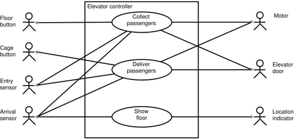
The relationship between the use cases and external entities in the environment of the elevator controller are depicted in Fig. 2.
Elevator controller Collect passengers Deliver passengers Show floor Floor button Cage button Entry sensor Arrival sensor Motor Elevator door Location indicator
In our approach, the actors in the use case diagram are the external entities that the controller directly interacts with. These entities are given, and we cannot change them or affect them in our development project, but we must know how they behave. This conception of actors in a use case diagram may deviate from more common conventions. As an example, many use case diagrams for the el-evator controller would include a ”passenger” actor. We do not do this, because the elevator controller does not interact directly with passengers, but merely with buttons and sensors operated by and affected by passengers behaviour.
Let us take a closer look at the use case Collect passengers, whose trigger event is the push of a floor button. This should generate a stimulus to the elevator controller, which, upon reception, must do a number of things:
(1) The controller must turn on the light of the pushed button;
(2) The controller must allocate the request to one of the cages. In particular, this implies that the controller must determine whether the request can be served immediately. This is possible only if the request comes from a floor where there currently is an idle cage. In this case, the cage can just open its doors; it is not necessary to start the motor;
(3) If it is necessary to start the motor, the controller must generate an appropriate signal to the motor;
(4) If it is sufficient to open the doors, the controller must generate a signal to the doors instructing them to open.
We could illustrate this scenario and its continuation with cages moving, sen-sors being triggered etc. using, e.g. sequence diagrams. Alternatively, we could describe the desired general behaviour of the elevator controller and the entities in its environment using statecharts [Harel 1987]. This is done, e.g. in Wieringa [2003]. However, our objective with this paper is to demonstrate the applicability of CPN in object-oriented analysis and design (statecharts and CPN models have their advantages and disadvantages in comparison with each other, see, e.g. Elk-outbi and Keller [2000] and also Jørgensen and Christensen [2002]). Therefore, instead, we will describe the desired general behaviour using CPN. We do so in the next section.
3. Requirements-level CPN Model
The requirements-level CPN model, which we will present in this section, models the desired behaviour of the environment as controlled by the elevator controller. The model is created and executed with the tool CPN Tools [CPN Tools 2004], which allows the creation of graphical models and includes the programming lan-guage Standard ML [Milner et al. 1997]. Together with the explanation of the model, this section is an informal primer to the CPN language itself, which allows the reader to understand the model in general terms — although we do not explain all the technicalities.
An earlier version of the requirements-level model has been previously presented in the technical report Jørgensen [2004] describing how the requirements-level
CPN model is constructed based on given traditional documentation taken from Wieringa [2003]. Thus the current paper supplements Jørgensen [2004] by dis-cussing how the requirements-level CPN model can be used as a basis for design-level models, which are closer to an implementation.
The CPN model consists of (1) declarations of data types, functions, etc. and (2) a graphical net structure in the form of three related modules: Do Cage Cycle, Handle Requests, and Move UpDown. As we will see, the declarations are used as inscriptions in the graphical net structure.
3.1 Representation of Entities
Entities in the environment are represented via data type declarations. This applies both to the environment entities, which can be seen from the use case diagram in Fig. 2, but also to relevant entities with which the controller does not interact directly, but which it controls via other entities — e.g. the controller controls a cage because the controller interacts with the cage’s motor.
As an example, the data type CAGE used to represent the elevator cages consists of 4-tuples of the form (cageid,floor,requestlist,direction):
◦ cageid identifies the cage;
◦ floor is the number of the floor where the cage currently is, if the cage is stationary, or has last visited, if the cage is moving;
◦ requestlist is the cage’s request list represented as a list of floor numbers; it is assumed that the controller will maintain a request list for each cage recording the outstanding requests currently allocated to that particular cage; ◦ direction holds the cage’s current direction of movement: up, down, or no. Other examples are floors that are represented as integers, and floor buttons that are represented as pairs (floor,direction), where direction is no if the button has not been pushed and otherwise up or down, indicating the passen-ger’s direction request. The cage buttons in each cage are represented as a pair (cageid,buttonlist), where buttonlist is a list of integers corresponding to the floors for which cage buttons have been pushed and the respective generated requests have not been served yet.
3.2 Representation of Cage Behaviour
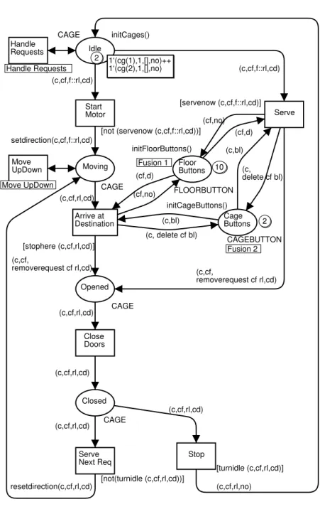
The basic behaviour of cages is modelled in the Do Cage Cycle module, shown in Fig. 3.
A CPN model describes both states and events. The state of a CPN model is a distribution of tokens on places, drawn as ellipses. Each place has a data type, writ-ten in capital letters, which determines the kinds of tokens the place may contain. In Fig. 3, the two elevator cages are modelled by CAGE tokens. Each CAGE token is at any time on exactly one of the places Idle, Moving, Opened, or Closed, which all have data type CAGE. The Floor Buttons and Cage Buttons places are used to model the floor buttons and cage buttons, respectively. Tokens on these places correspond to buttons and model whether buttons are on or off.
Idle 2 1‘(cg(1),1,[],no)++ 1‘(cg(2),1,[],no) CAGE initCages() Moving CAGE Opened CAGE Closed CAGE Start Motor [not (servenow (c,cf,f::rl,cd))] Serve [servenow (c,cf,f::rl,cd)] Arrive at Destination [stophere (c,cf,rl,cd)] Serve Next Req [not(turnidle (c,cf,rl,cd))] Close Doors Stop [turnidle (c,cf,rl,cd)] (c,cf,f::rl,cd) setdirection(c,cf,f::rl,cd) (c,cf,rl,cd) (c,cf, removerequest cf rl,cd) (c,cf,f::rl,cd) (c,cf,rl,cd) resetdirection(c,cf,rl,cd) (c,cf,rl,cd) (c,cf,rl,cd) (c,cf,rl,cd) Handle Requests Handle Requests Move UpDown Move UpDown Floor Buttons 10 FLOORBUTTON initFloorButtons() Fusion 1 Cage Buttons 2 CAGEBUTTON initCageButtons() Fusion 2 (cf,d) (c,bl) (c, delete cf bl) (cf,d) (cf,no) (c,bl) (c, delete cf bl) (cf,no) (c,cf, removerequest cf rl,cd) (c,cf,rl,no)
Fig. 3: Do Cage Cycle module.
The state shown in Fig. 3 is the model’s initial state, which represents a situation, where both elevator cages are idle on floor 1 and no requests have been made; this is also the state in Figs. 4 and 5 to be shown later. The number of tokens on a place is indicated by an integer in a small circle close to or on the place. In CPN Tools,
a click on the small circle opens a box, which shows the current state of the place — that has been done for place Idle, where the contents of the two CAGE tokens can be seen. For places Floor Buttons and Cage Buttons, only the number of tokens can be seen. The remaining places (Moving, Opened, and Closed) are empty, and no small circles are shown.
The events of a CPN model are represented using transitions, drawn as rectan-gles. Arcs connect transitions with places. The events consist of transitions that remove tokens from input places and add tokens to output places. The expression associated with an arc determines the removed or added tokens: e.g. the expres-sion (c,cf,f::rl,cd) appearing on the arc from the Idle place to the Start Motortransition specifies a CAGE token in which the third entry matches the pat-tern f::rl, i.e. is a non-empty list (c, cf, f, rl, and cd are variables of appropriate data types).
A transition that is ready to remove and add tokens is enabled; it may occur. There are two conditions for enabling:
(1) Appropriate tokens are present on the input places — the values in these tokens are bound to the variables appearing in the inscriptions around the transition;
(2) A guard — a Boolean expression in square brackets — is true.
In Fig. 3, enabling of Start Motor requires: (1) that Idle contains some CAGEtoken that matches the pattern (c,cf,f::rl,cd), i.e. a CAGE token with a non-empty request list; and (2) that the guard [not (servenow (c,cf,f::rl, cd))]evaluates to true; i.e. that the state represents a situation in which cage c is not currently at floor f. Start Motor is not enabled in the shown state. However, when other transition occurrences in the CPN model have changed the state, Start Motorcan become enabled and can occur. This models that a cage changes from being idle to be moving: a CAGE token is removed from Idle and a CAGE token is added to Moving; the latter token with its direction entry determined by the call of the setdirection function.
Occurrence of Arrive at Destination models that a cage arrives at a floor, stops, and opens its doors. This causes updates of tokens representing buttons on the Floor Buttons and Cage Buttons places to model that the request buttons for the current floor are turned off. Also, the request for the current floor is removed from the request list of the CAGE token by the call of the removerequest function on the arc from Arrive at Destination to Opened.
Occurrence of Close Doors models that a cage closes its doors: The token representing the cage is put on Closed. The Stop transition is enabled if the CAGEtoken has an empty request list; this is checked by the turnidle call in the guard. Serve Next Req is enabled if the request list is non-empty, In this way, it is modelled that the cage either can become idle or resume its movement.
Handle Requestsand Move UpDown in Fig. 3 are special kinds of transitions that refer to the two other modules of the model, which we describe below.
3.3 Representation of Requests Handling
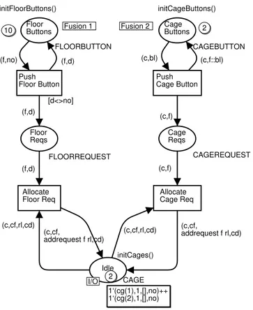
The handling of requests, i.e. the making and subsequent allocation of requests to cages, is modelled in the Handle Requests module, shown in Fig. 4.
Floor Buttons 10 FLOORBUTTON initFloorButtons() Fusion 1 Cage Buttons 2 CAGEBUTTON initCageButtons() Fusion 2 Floor Reqs FLOORREQUEST Cage Reqs CAGEREQUEST Idle 2 1‘(cg(1),1,[],no)++ 1‘(cg(2),1,[],no) CAGE initCages() I/O Push Floor Button [d<>no] Push Cage Button Allocate
Floor Req AllocateCage Req (f,no) (f,d) (f,d) (c,cf, addrequest f rl,cd) (c,bl) (c,f) (c,f) (c,cf, addrequest f rl,cd) (c,cf,rl,cd) (c,cf,rl,cd) (c,f::bl) (f,d)
Fig. 4: Handle Requests module.
Each of the places Idle, Floor Buttons and Cage Buttons is conceptually glued with the place with the same name in the Do Cage Cycle module. In a hierarchical CPN model, there are two ways to glue places. One way is to glue a socket place on one module with a corresponding port place on another module; the socket place must be connected to a substitution transition. An example of this are the Idle places, where Idle on the Do Cage Cycle module is connected to the Handle Request substitution transition. The other way is to put places in the same place fusion set; this has been done to the Floor Buttons places and the Cage Buttonsplaces, respectively.
Occurrence of the Push Floor Button transition models that a passenger pu-shes a floor button, either in direction up or down. This will cause the floor button to light up, modelled in the CPN model by an update of a floor button token on Floor Buttons; that the light of the floor button is eventually turned off again is modelled by occurrence of either the Serve or, as we saw, the Arrive at Destination
transition in the Do Cage Cycle module (Fig. 3).
The occurrence of Push Floor Button also causes a FLOORREQUEST token to be added to Floor Reqs. Subsequently, this may cause Allocate Floor Req to become enabled; Allocate Floor Req models assignment of a given floor request to one of the two elevator cages. In the current version of the model, the scheduling policy is very simple: a random idle elevator is chosen.
Occurrence of Push Cage Button models that a passenger pushes a cage but-ton. Similarly to Push Floor Button, this causes an update of a token on Cage Buttonsmodelling that the button lights up. It also causes a CAGEREQUEST token to appear on Cage Reqs. Occurrence of Allocate Cage Req models that the request is added to the request list of the cage in which the button is pushed — which, of course, is the only sensible way to allocate a cage request.
3.4 Representation of Up and Down Movement
The up and down movement of the elevator cages is modelled in the Move UpDown module, shown in Fig. 5.
Location Indicators 2 1‘(cg(1),1)++1‘(cg(2),1) LOCATIONINDICATOR initLocationIndicators() Moving CAGE I/O Move One Up [cd=up,cf<10,not(stophere (c,cf,rl,cd))] Move One Down [cd=down,cf>1,not(stophere (c,cf,rl,cd))] (c,cf,rl,cd) updatelocationindicators c l up (c,cf,rl,cd) updatelocationindicators c l down (c,cf+1,rl,cd) (c,cf-1,rl,cd) (c,l) (c,l)
Fig. 5: Move UpDown module.
The Moving place is conceptually glued with the place with the same name in the Do Cage Cycle module (Fig. 3).
The Move One Up transition models movement of an elevator cage one floor up. When it occurs, the floor entry of the CAGE token on Moving is incremented, as can be seen from the expression on the arc from Move One Up to Moving. The guard of Move One Down consists of three Boolean expressions and should be read as a conjunction. The expressions cd=up and cf<10 model properties that are inherent to the environment: that the cage actually is moving upwards and that it cannot move up if it is at the topmost floor. The expression not(stophere (c,cf,rl,cd)) models a condition that is enforced by the elevator controller:
that the cage only moves if it should not stop — it should stop if there is a request. The Move One Down transition works similarly to Move One Up.
Tokens on the Location Indicators place model the location indicators for the two elevator cages. The state of Location Indicator is updated each time either Move One Up or Move One Down occurs. The call of the function update locationindicators emulates the controller’s responsibility of ensuring that each location indicator correctly displays the actual current floor of the elevator cage. In terms of the CPN model, this means that the floor entry of each of the tokens on Location Indicators must be equal to the floor entry of the corre-sponding CAGE token — which is on one of the places Idle, Moving, Opened, or Closed.
4. From Requirements-level to Design-level Models
The requirements-level CPN model can be seen as an executable use case in the sense of Jørgensen and Bossen [2004]. This is described in more detail in Jørgensen [2005], where the CPN model is used in a prototyping fashion to drive a graphical animation. The execution of the model can be used to validate the three use cases of Fig. 2. More generally, the CPN model can be used as a vehicle for requirements engineering: the model and its execution can be used to specify, validate, and elicit requirements for the elevator controller.
The model describes when the controller should interact with external entities like motors, buttons, sensors, and doors. The model also describes what should be the effect of such interactions in the environment. Neither the CPN model, nor the use case diagram in Fig. 2, explicitly describe details of the software we are designing for the elevator controller. The elements of both the use case diagram and the CPN model are to be thought of as real-world elements, like a real motor, a real button, and a real door.
To design the elevator controller, we need to move from the environment-level descriptions we have, to a description of the software. This involves the deriva-tion of a design-level model, thus specifying the constructs and concepts found in object-oriented programming languages. To that end, we can and we should take advantage of what we have learned while constructing the requirements-level CPN model. We use that knowledge to build a design-level model, which includes two views:
(1) A class diagram, as a structure diagram;
(2) An object-oriented CPN model, for the specification of behaviour, which will be referred as the design-level object-oriented CPN model or simply as the design-level CPN model.
In the sense of Damm and Harel [2001], the latter includes intra-object behaviour — the behaviour of the individual objects of a class — and inter-object behaviour — communication and cooperation between objects of different classes.
In our approach, we explicitly pay attention to and describe entities in the real world at the requirements-level, as we have seen. Then, we make an explicit tran-sition from considering real-world entities to considering software at the
design-level. The importance of distinguishing between the real world, on one hand, and the software, on the other hand, is advocated by a number of software experts, see, e.g. Jackson [2001]. However, this distinction is not always made explicitly in object-oriented analysis and design, where it is not always clear whether the classes in a class diagram are to be conceived as real-world entities or as software. Letting it be up to the reader of a class diagram to decide whether one or the other interpretation is applicable may cause confusion.
The following section presents a class diagram obtained from the use cases and the requirements-level model in Figs. 3, 4, and 5. Section 6 presents the corre-sponding design-level object-oriented CPN model. Yet, in practice, the class dia-gram should be build in iterative steps together with the design-level CPN model as each one emphasises distinct system views, thus supplementing the other.
5. Class Diagram
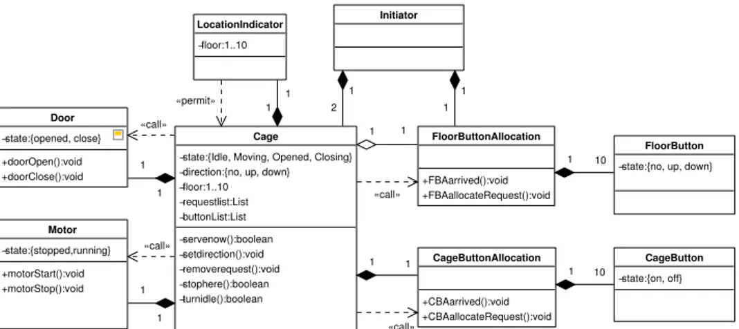
A class diagram for the elevator controller is shown in Fig. 6.
Cage
−state:{Idle, Moving, Opened, Closing} −direction:{no, up, down} −floor:1..10 −requestlist:List −buttonList:List −servenow():boolean −setdirection():void −removerequest():void −stophere():boolean −turnidle():boolean FloorButton
−state:{no, up, down}
Door −state:{opened, close} +doorOpen():void +doorClose():void Motor −state:{stopped,running} +motorStart():void +motorStop():void LocationIndicator −floor:1..10 Initiator FloorButtonAllocation +FBAarrived():void +FBAallocateRequest():void CageButtonAllocation +CBAarrived():void +CBAallocateRequest():void CageButton −state:{on, off} 1 2 1 1 1 1 1 1 1 10 «call» «call» «permit» 1 1 1 1 «call» «call» 1 1 1 10
Fig. 6: Class diagram for the elevator controller.
The class diagram should be compared with the use case diagram of Fig. 2. Each class in the class diagram, which has a name similar to the name of an actor in the use case diagram, is the software representation of that actor inside the elevator controller, e.g. instances of the FloorButton class represent the real-world, phys-ical floor buttons. In addition to the classes representing actors from the use case diagram, the class diagram contains the classes Cage, FloorButtonAllocation, CageButtonAllocation, and Initiator.
The elevator controller will contain two instances of the Cage class; each one represents one of the two real-world cages. The state of each cage object reflects the information about the real world that the controller needs in order to do its job: e.g. that information includes knowledge of the position and direction of movement of the modelled cage. Many attributes and operations of the classes in the class diagram are derived from the requirements-level CPN model. Yet, as
the class diagram has been created after the requirements-level CPN model, there are some differences, which are due only to an increased understanding of what it is needed to include in the models: e.g. there are no ”motor tokens” in the requirements-level CPN model — although there might as well have been — but there are explicit representations of motor objects in the class diagram. There, the motors are ”first class entities” (modelled as instances of a class Motor); they are explicitly commanded, by the Cage objects, to start and stop. These commands are modelled by object operations. The same was done for elevator doors, which are commanded to open and close by the Cage objects.
The classes FloorButtonAllocation and CageButtonAllocation are used to model allocation of requests to cages. More specifically, they group the several cage and floor buttons and delegate the request handling to the respective button classes: FloorButton and CageButton. Taken together, they play a similar role to the Handle Requests module in Fig. 4.
There is exactly one instance of the Initiator class; its only aim is to create other objects inside the elevator controller, namely the two Cage objects and the FloorButtonAllocation. As already stated, the latter groups the floor buttons. For that reason it is not made part of the Cage objects.
The LocationIndicator class plays a similar role to the Move Up Down mod-ule in Fig. 5; its objects have direct access to the respective Cage object’s private attributes and update the location indicators while the cage is in state Moving.
As noted in Kruchten [2004], objects and classes are most likely found by walk-ing through the use cases; e.g. the books Jacobson et al. [1999] and Douglass [2004] provide concrete advice on the connection between use cases, classes, and objects. Besides taking into account the use cases, the approach we have used to construct the presented class diagram also considers the connection to the require-ments-level CPN model. Due to its generality, we believe our approach can be applied to other models. The approach is summarised by the following points:
◦ The general view should be the one from object-oriented development, that means the model should be seen as a set of interacting objects that, in each interaction, act as a client or as a server; the former asks for a service and the latter provides it; only for the specification of particularly complex oper-ations, should we think of hierarchical decomposition and always inside one specific class;
◦ Each actor, in the use case diagram, is a candidate to a class in the class diagram; note that these actors can already be specified by data types (colour sets) associated to places in the requirements-level model; in those cases, the object attributes are the data type elements plus the object’s self reference; ◦ When reusing the requirements-level model functions in arc expressions, they
should be seen as private operations on the objects that model the data they manipulate;
◦ Some entities that do not appear explicitly can be good candidates to classes (in the example, this is the case with classes Motor and Door);
◦ When splitting the model in several classes, we need to model operations; these are expressed as public operations.
6. Design-level Object-oriented CPN Model
The design-level CPN model describes the software that we must develop. As we want to construct object-oriented software and to establish a clear connection between CPN models and well-known object-oriented artifacts we need to achieve two objectives:
(1) To allow the use of class diagrams as a starting point for the construction of design-level object-oriented CPN models;
(2) To describe the behaviour (both inter-object and intra-object) for the objects whose classes were identified in the class diagram while using constructs conceptually close to the ones found in mainstream object-oriented program-ming languages.
These objectives are made possible through the use of five idioms for the con-struction of design-level object-oriented CPN models:
(1) The creation of a CPN module for each class in the class diagram;
(2) The explicit creation of each object by a create operation just like in object-oriented programming languages;
(3) The use of one token for each object in the CPN module for the respective class; those tokens contain the object self reference — given by the create operation — and the object attributes, again just like in object-oriented pro-gramming languages;
(4) The use of a high-level form of transition fusion — named synchronous chan-nels – for modelling operations and operation calls, as proposed in Barros and Gomes [2004];
(5) The use of place fusions, as provided by CPN Tools, for modelling of public access to object attributes.
Next, we present, in detail, the CPN module for Motor class and the CPN module for Cage class, both part of the class diagram in Fig. 6. Those modules exemplify the use of the presented idioms.
6.1 CPN Module for Motor Class
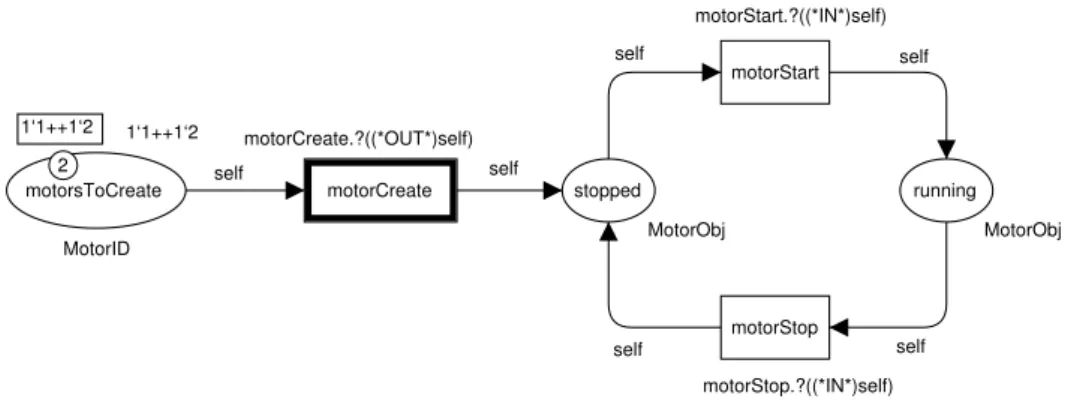
Fig. 7 shows the design-level CPN module for the Motor class (see Fig. 6), which exemplifies the modelling of a class behaviour by a CPN. When defining the CPN module for a class we use the tokens to carry the object reference plus all the object attributes. As each object is modelled by a token, the CPN module of a given class models the behaviour of all class instances.
The CPN module for class Motor models the behaviour for the two objects that we use to represent the two motors with two possible states: stopped and running. The objects are created by transition motorCreate. This transition has an associated receive channel, specified by the syntax channelName.?(parameters), where the ? stands for the receive part of the channel. In object-oriented terms, one can think of it as a class operation as it does not receive an object reference and, as in this case, it typically returns a new object reference (the self attribute).
motorsToCreate MotorID 1‘1++1‘2 2 1‘1++1‘2 stopped MotorObj running MotorObj motorCreate motorStop motorStart self self self self self self motorCreate.?((*OUT*)self) motorStart.?((*IN*)self) motorStop.?((*IN*)self) Fig. 7: CPN for the Motor class, using channels.
In the presented example, the motorCreate operation is called from transition cageCreateBegin, which is part of the design-level CPN model for class Cage (top-left corner of Fig. 9), which we will describe later.
The place motorsToCreate specifies that only two different objects can be cre-ated. For each firing of transition motorCreate, one Motor object is crecre-ated. In this simple case, as the object’s state is modelled by places stopped and running, its only attribute is the variable self, which is the object self reference. When a Motorobject is created its state is stopped. This is specified by place stopped in Fig. 7. Later, after transition motorStart firing, a Motor object state can take the value running.
Each Motor object has two public operations, whose single effect is to change the object state: motorStart and motorStop. Each of these operations is modelled by a transition and an associated receive channel with the same name. An instance operation has the object reference as one of its parameters. This has the advantage of being similar to the syntax and semantics commonly found in object-oriented programming languages.
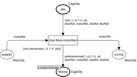
An operation call is specified by the send part of a channel and has the syntax channelName.!(parameters). The channel’s semantics is defined by the fusion of the two transitions (with the send and receive parts). The resulting transition has a guard which is the conjunction of both guards. As an example, Fig. 8 shows a transition (named Start motor/motorStart) with the equivalent semantics to the synchronous channel motorStart between transition Start motor in the CPN module for class Cage (see Fig. 9) and transition motorStart in the CPN module for class Motor (see Fig. 7).
6.2 CPN Module for Cage Class
Fig. 9 shows the design-level CPN model for class Cage. The requirements-level model in Fig. 3 defined a CAGE data type with the form (cageid, floor, requestlist, direction). For the class model, all these four ele-ments are defined as attributes for Cage objects. We also define, as Cage
ob-stopped MotorObj running MotorObj Moving CageObj LocationIndicator Idle CageObj Start Motor/motorStart [not (servenow(c, cf, f::rl, cd))] setdirection(self, c,cf, f::rl, cd, doorRef, motorRef, cbaRef, fbaRef) (self, c, cf, f::rl, cd,
doorRef, motorRef, cbaRef, fbaRef)
motorRef motorRef
Fig. 8: Transition fusion for channel motorStart.
jects’ attributes, the references to the composite objects CageButtonAllocation, LocationIndicator, Door, and Motor, and the reference to the aggregate ob-ject FloorButtonAllocation. Hence, each Cage obob-ject has the form (self, cageid, floor, requestlist, direction, doorRef, motorRef, cbaRef, fbaRef). Besides the variable self for the objects’ self reference, we use vari-ables with the syntax nameRef for specifying references to other objects. The remaining variables are the ones used for the requirements level model in Fig. 3.
The CPN module for Cage class has the same basic structure as the Do Cage Cyclemodule in Fig. 3. The differences are due not only to the structure imposed by the class diagram, namely the creation of one CPN module for each class, but also to the increased modularity made possible by the use of synchronous channels. More specifically, the synchronous channels allow us to map operations in the class diagram, and their invocations, to design-level CPN models.
Whereas the initial Do Cage Cycle module (Fig. 3) assumes that both ca-ges initially exist in the Idle state, the CPN module for Cage class models the cage objects creation explicitly. We decided to explicitly model object creation in all classes for two reasons: (1) it makes the model conceptually closer to object-oriented specifications as all objects need to be created; (2) it allows a clear vi-sualisation of composition and aggregation relations between objects.
The operation cageCreateBegin creates a Cage object (and so it returns the new object reference), and also calls the create operations for all the composite objects. The arc expressions 1‘cageObj1 ++ 1‘cageObj2 in transition’s cage CreateEnd input and output arcs guarantee that both objects enter place (state) Idlein the same instant. Differently, the reference for the aggregate FloorButton Allocation object (fbaRef) is received from the object Initiator that also creates the cage object.
The CPN module for class Motor (see Fig. 7) returns the object reference (self) through the channel motorCreate. This reference is then used by the Cage objects
Idle CageObj Moving CageObj LocationIndicator Opened CageObj Closing CageObj beingCreated CageObj cageToCreate CageID 1‘1++1‘2 2 1‘1++1‘2 Start Motor [not (servenow (c, cf, f::rl,cd))] Serve [servenow (c, cf, f::rl,cd)] Arrive at Destination [stophere cf rl] Serve Next Req [not(turnidle (c,cf,rl,cd))] Close Doors Stop [turnidle (c,cf,rl,cd)] cageCreateBegin cageCreateEnd allocateCageRequest allocateFloorRequest (self, c,cf,f::rl,cd,
doorRef, motorRef, cbaRef, fbaRef)
setdirection(self, c,cf,f::rl,cd, doorRef, motorRef, cbaRef, fbaRef)
(self, c,cf,rl,cd,
doorRef, motorRef, cbaRef, fbaRef)
(self, c,cf, removerequest cf rl, cd, doorRef, motorRef, cbaRef, fbaRef)
(self, c,cf,f::rl,cd,
doorRef, motorRef, cbaRef, fbaRef)
(self, c,cf, removerequest cf rl,
cd, doorRef, motorRef, cbaRef, fbaRef)
(self, c,cf,rl,cd, doorRef, motorRef, cbaRef, fbaRef)
resetdirection(self, c,cf,rl,cd, doorRef, motorRef, cbaRef, fbaRef) (self, c,cf,rl,cd,
doorRef, motorRef, cbaRef, fbaRef)
(self, c,cf,rl,no, doorRef, motorRef, cbaRef, fbaRef) (self, c,cf,rl,cd,
doorRef, motorRef, cbaRef, fbaRef)
(self, c,cf,rl,cd,
doorRef, motorRef, cbaRef, fbaRef) (self, c,1,[],no, doorRef, motorRef, cbaRef, fbaRef) self 1‘cageObj1++1‘cageObj2 (self, c,cf,rl,cd,
doorRef, motorRef, cbaRef, fbaRef) (self, c,cf, addrequest f rl, cd, doorRef, motorRef, cbaRef, fbaRef)
(id, c,cf,rl,cd,
doorRef, motorRef, cbaRef, fbaRef) (self, c,cf, addrequest f rl, cd,
doorRef, motorRef, cbaRef, fbaRef)
1‘cageObj1++1‘cageObj2 CBAarrived.!((*IN*)cbaRef, (*IN*)cf) FBAarrived.!((*IN*)fbaRef, (*IN*)cf) doorOpen.!((*IN*)doorRef) CageCreate.?((*IN*)c, (*IN*)fbaRef, (*OUT*)self) doorCreate.!((*OUT*)doorRef) motorCreate.!((*OUT*)motorRef) CBAcreateBegin.!((*IN*)cc,10, (*OUT*)cbaRef) LIcreate.!((*IN*)self) motorStart.!((*IN*)motorRef) doorClose.!(doorRef) CBAallocateRequest.!( (*IN*)cbaRef, (*IN*)cf) CBAarrived.!((*IN*)cbaRef, (*IN*)cageFloor) FBAarrived.!((*IN*)fbaRef, (*IN*)cageFloor) motorStop.!((*IN*)motorRef) doorOpen.!((*IN*)doorRef) motorStart.!((*IN*)motorRef) FBAallocateRequest.!( (*IN*)cbaRef, (*IN*)cf)
Fig. 9: CPN for the Cage class, using channels.
as the motorRef variable. The Door class is handled in the same way.
When compared to the Do Cage Cycle module, the CPN module for class Cage has three main differences:
tionIndicator. Yet, this class behaves in a very similar way to the mod-ule, as the communication with the Cage objects is still done through the place Moving. Now, this place is seen as a public part (one can think of it as a public attribute) of class Cage. A LocationIndicator object is created, in transition cageCreateBegin, by each Cage object, which passes its own reference to the LocationIndicator object (LIcreate.!((*IN*)self)); later, the LocationIndicator object uses the Cage reference when asyn-chronously communicating with the Cage object; this is achieved through fu-sion of one place in LocationIndicator class with place Moving in class Cage;
(2) The cage buttons requests are now handled by the CageButtonAllocation class together with the CageButton class; likewise, the floor buttons’ re-quests are now handled by class FloorButtonAllocation together with FloorButton; channels associated to transitions Arrive at Destination and Serve are now responsible for updating the buttons’ state; additional transitions allocateCageRequest and allocateFloorRequest get the pending requests, through the associated channels, from the CageButton Allocation class and the FloorButtonAllocation class, respectively; note that we could also model these channels as receiving channels; in that case the CageButtonAllocation and FloorButtonAllocation objects would send the new requests to the respective Cage object;
(3) The cage door and cage motor are now created as composite objects (in tran-sition cageCreateBegin); the Motor class objects change state through channels motorStart and motorStop; the Door objects change state through channels doorOpen and doorClose.
Compared with the requirements-level CPN model, the object-oriented design-level CPN model that we have just presented allows us to take advantage of the class diagram structure and is a step towards code in an object-oriented program-ming language; this is discussed in the next section.
7. From Design-level Models Towards an Implementation
The straightforward approach to execute a CPN model is to use a simulator like CPN Tools or R [RENEW 2004]. Yet, this is not always possible as the model may have to be run on a platform where the simulator is not available or has insuf-ficient performance. The alternative is a code generation approach as this allows code optimisations adaptable to each software and hardware platform.
One way to implement a CPN model is to translate it into a state machine. More specifically, each possible step is translated to an arc and each reachable net mark-ing is translatable to a state. Yet, this state machine will probably be too large to be useful in practice: in fact, through that approach we will be implementing the complete state space. In many cases, this is not a solution, as the state space is sim-ply too large. Yet, for small enough state spaces this can be an efficient solution, especially for hardware platforms, which have limited memory resources but are able to efficiently execute state machines. These state machines can be coded in
ANSI C, which is usually available for embedded operating systems. This path al-lows the design, in a high-level specification language, of object-oriented models, which are finally implemented as a state-machine. In this sense, a CPN model can be seen as a higher-level alternative to a state-machine (or statechart) based model. The alternative approach is to generate an interpreter for the model. This could be implemented as two distinct packages: (1) the net structure specification; (2) the net executor.
The following guidelines allow a straightforward centralised implementation for the net structure, in a general object-oriented programming language (e.g. Java or C++):
◦ Each Colour Type is defined as a class; ◦ Each CPN module is implemented as a class;
◦ Each place, transition, and arc, is an object of class Place, Transition, and Arc, respectively;
◦ Each CPN class contains as attributes the respective module variables, tran-sitions and places;
◦ Each place object contains a bag of elements of the data type associated to the place in the net model (the place colour);
◦ Each transition object has four methods:
(1) One to test the transition state (enabled or not enabled);
(2) One to fire the transition, accordingly changing the markings of the re-spective input and output places;
(3) One implementing the guard;
(4) One implementing the code segment.
◦ Each arc object has a reference to a place object and a reference to a tran-sition object; it also contains a method implementing the arc expression and returning a value of the place colour;
◦ Each port place, in a hierarchical CPN, is a reference attribute to a place object in another class;
◦ Each place fusion, again for a hierarchical CPN, is coded as a place object and a set of place object references.
For each execution step, the net executor package executes three sub-steps: (1) Calculates the set of enabled transitions;
(2) Chooses a subset to fire;
(3) Fires the transitions in the chosen subset.
For large nets, the first sub-step can impose a significant computation delay, as the binding computation has the potential to become the execution bottleneck. Yet, this computation can be minimised by testing only the transitions where, at least, one input place has changed its marking in the previous step.
The usual memory versus speed compromise clearly shows up when implement-ing CPN models: either the CPN model compactness, compared to a low-level Petri net, has to go away through the total unfolding of the model, in the form of a
state-machine; or we implement a direct execution implying the binding’s compu-tation, which is slower although more memory efficient.
Finally, we stress that the general solution for code generation from CPN models should consider distributed architectures. This a complex issue for which further research is clearly needed. Interestingly, synchronous channels and place fusion already provide the abstractions for synchronous communication and shared mem-ory. A possible line of research is to investigate the use of shared memory, ex-plicitly modelled by place fusion, for communication between distinct centralised architectures (or processors) that do not share the same clock signal. Inside each centralised architecture, either place fusion or synchronous channels can be used.
8. Related Work
The use of Petri nets in conjunction with object-orientation has been studied in-tensively in recent years. Much of the work done is concerned with automatic translation from certain types of UML diagrams into Petri nets, often aimed at for-mal verification, e.g. Saldhana and Shatz [2000]. Also, Petri nets have been used to give precise execution semantics to different classes of UML diagrams, e.g. Baresi and Pezz`e [2001]. A small number of examples of combined use of UML and CPN in software development have appeared in the literature, e.g. design of user interfaces is described in Elkoutbi and Keller [2000].
Much research has addressed the development of concepts and theories that com-bine the ideas of object-orientation in general and Petri nets [Agha et al. 2001]. Specifically, in Lakos [2001], Object Petri Nets are defined, which extend CPN with object-oriented features like inheritance and polymorphism. Other examples of work in this area are Bibersteinet al. [2001], Giese et al. [1999], and Maier and Moldt [2001]. Differently from all these approaches, in this paper we have used plain CPN to construct object-oriented models. This was made possible through the use of a small set of idioms. These rely on synchronous channels and place fusion to mimic object-oriented concepts and constructs like creation and destruc-tion of objects, message passing, and data sharing. As the presented example does not use any kind of inheritance, it does not exhibit all the common features of object-oriented languages. According to the classification in Wegner [1987], the example is somewhere between ”class-based” and ”object-oriented”. Yet, it should be noted that polymorphism is easily modeled: we just need to add a variable pa-rameter specifying the class where the receive side of the channel is defined. Then, the dynamic binding of that parameter corresponds to a polymorphic invocation (a dynamic dispatch) of the respective receive channel. Regarding implementation inheritance, we do not have a good solution. Yet, we do believe, as many other authors (e.g. [Gammaet al. 1995]), that implementation inheritance should be re-placed by composition. Regarding type inheritance (as found, e.g. on Java), it is trivially supported as we do not model interfaces (types) but only the classes that implement them. Even the inheritance from abstract classes, in the sense of ”in-terfaces with attributes”, can be modeled by the derived classes alone, where each one has to support the attributes in the abstract class.
The channels for synchronous communication were first proposed in Christensen and Hansen [1994]. They bring the transition fusion concept to CPN. In particu-lar, transitions are able to communicate complex values. By allowing synchronous communication modelling in CPN plus data communication, synchronous chan-nels offer an effective way to create more compact and readable models. The ini-tial proposal by Christensen and Hansen is totally symmetric, namely there is no sender and receiver sides for each channel. Kummer [1998] proposed a direction of invocation to each channel: we get sender and receiver sides for each channel. Yet, the parameters are still bidirectional: e.g. one net (using a send channel in one of its transitions) can pass a value through one parameter and receive a value from an-other parameter. Barros and Gomes [2004] proposed to further disambiguate this bidirectional nature for channel parameters by qualifying the parameters as IN, OUT, or INOUT. These qualifiers give channels a parameter passing semantics simi-lar to the ones usually found in imperative object-oriented programming languages. The direction of invocation makes channels closer to method invocation. Here, we used the qualifiers inside Standard ML comments, as they are not supported by CPN Tools. Presently, the same happens to synchronous channels. It is clear that if we want to generate executable, autonomous code from a CPN model, we should use the inscription language as the target programming language. CPN Tools uses Standard ML as the inscription language. Hence, it is easier to generate Standard ML code for model execution [see Mortensen 1999; Kristensen and Christensen 2004]. Another approach is to use a code-level library, in the target language, sup-porting the net execution and add it to a net structure specification also in the target language (e.g. [Reinke 2000]). A general object-oriented language can also be used. A significant example is the R tool [RENEW 2004], which supports an extension to CPN, is written in Java, and uses Java as the inscription language.
9. Conclusions and Future Work
CPN models as we have presented them in this paper might candidate to be used in object-oriented analysis and design, e.g. in development projects tailored from the widely used Rational Unified Process (RUP) [Kruchten 2004]. RUP emphasises the use of UML models as key artifacts in software development. If a deviation from UML is acceptable by the project stakeholders, creating and executing CPN models fit well in the elaboration phase or the inception phase of RUP. However, a major effort is clearly needed to transfer the specific observations done in the small case study of this paper into generally applicable guidelines for the interplay between traditional RUP artifacts like use case diagrams and class diagrams and various kinds of CPN models.
Compared to many other graphical languages for behaviour description, CPN have the following advantages:
(1) They have a precise syntax and semantics; (2) They are executable;
(3) They are verifiable;
As already pointed out, they lack clear connections to a structure diagram. This was addressed here through the use of a set of idioms that allow the creation of design-level object-oriented CPN models. These idioms include the use of chan-nels for synchronous communication. In particular, transitions are able to com-municate complex values. By allowing synchronous communication modelling in CPN plus data communication, synchronous channels improve models modularity and readability. Together with the presented idioms, they allow the designer to think and model in object-oriented terms (see also Barros and Gomes [2004]). In this way, they provide a one-to-one relationship between classes and modules of a CPN model, thus establishing a clear connection between class diagrams and CPN models.
The transformation between design-level object-oriented CPN models and ex-ecutable autonomous code is still a subject for further work. In particular, the design-level object-oriented CPN model must be able to somehow reflect the plat-form specific architecture, code and data. Code segments associated to transition firing and CPN data declarations may facilitate this. Unfortunately, the literature and applications on the implementation of CPN models is still scarce. We attribute this situation to the Petri net’s community traditional bias towards model verifica-tion and analysis. This comes probably from the deeply formal and abstract Petri nets’ origin, as a mathematical object. Yet, CPN, even without further semantic extensions, are a class of Petri nets ready to be applied to object-oriented analysis and design of systems that, like the elevator controller, exhibit a static structure of interacting components.
References
A, G., C, F., R, G., E. 2001. Concurrent Object-Oriented Program-ming and Petri Nets, Advances in Petri Nets. Volume 2001 of Lecture Notes in Computer Science. Springer-Verlag.
B, L. P`, M. 2001. On Formalizing UML with High-Level Petri Nets. Volume 2001 of Lecture Notes in Computer Science. Springer-Verlag.
B, J. P. G, L. 2004. On the Use of Coloured Petri nets for Object-Oriented Design. In ICATPN 2004, Bologna, Italy, Cortadella, Jordi and Reisig, Wolfgang, Editors. Volume 3099 ofLNCS. Springer, 117–136.
B, O., B, D., G, N. 2001. Object-Oriented Nets with Algebraic Specifications: The CO-OPN/2 Formalism. Volume 2001 ofLecture Notes in Computer Science. Springer-Verlag.
C, S. H, N. D. 1994. Coloured Petri Nets Extended with Channels for Syn-chronous Communication. InICATPN 1994, Zaragoza, Spain, Valette, R., Editor. Volume 815 ofLNCS. Springer, 159–178.
CPN T. 2004. CPN Tools homepage. http://wiki.daimi.au.dk/cpntools.
D, W. H, D. 2001. LSCs: Breathing Life into Message Sequence Charts. Formal Methods in System Design 19, 45–80.
D, J. J´, G. 2001.What is a Petri net, Volume 2128 of LNCS. Springer, 1–25.
D, B. P. 2004. Real Time UML: Advances in the UML for Real-Time Systems. Addison-Wesley.
E, M. K, R. K. 2000. User Interface Prototyping Based on UML Scenarios and High-Level Petri Nets. Volume 1825 ofLecture Notes in Computer Science. Springer-Verlag, Aarhus, Denmark, 166–186.
Object-Oriented Software. Addison-Wesley.
G, H., G, J., W, G. 1999. Closing the Gap Between Object-Oriented Modeling of Structure and Behaviour. In UML 1999 - The Unified Modeling Language, 2nd
Interna-tional Conference, Volume 1723 of Lecture Notes in Computer Science. Springer-Verlag, Fort Collins, Colorado.
H, D. 1987. Statecharts: A Visual Formalism for Complex Systems. Science of Computer Programming 8, 231–274.
J, M. 2001.Problem Frames — Analyzing and Structuring Software Development Problems. Addison-Wesley.
J, I, B, G, R, J. 1999. The Unified Software Development Process. Addison-Wesley.
J, K. 1992-97. Coloured Petri Nets — Basic Concepts, Analysis Methods and Practical Use. Volume 1-3. Monographs in Theoretical Computer Science. An EATCS Series. Springer. J, J. B. 2004. CPN Models as Enhancements to a Traditional Software Specification for
an Elevator Controller. InProc. of 3rdWorkshop on Modelling of Objects, Components, and
Agents (MOCA’04). University of Aarhus, Aarhus, Denmark, 99–116.
J, J. B. B, C. 2004. Executable Use Cases: Requirements for a Pervasive Health Care System.IEEE Software 21, 2, 34–41.
J, J. B. C, S. 2002. Executable Design Models for a Pervasive Healthcare Middleware System. InProc. of 5thUML Conference, Volume 2460 of LNCS. Springer,
Dres-den, Germany, 140–149.
J, J.B. 2005. Towards Arguing the Cost-effectiveness of Coloured Petri Nets. InProc. of 2005 International Conference on Software Engineering Research and Practice. CSREA Press, Las Vegas, NV, USA, 246–252.
K, L. M. C, S. 2004. Implementing Coloured Petri Nets Using a Functional Programming Language.Higher-Order and Symbolic Compututation 17, 3, 207–243. K, P. 2004.The Rational Unified Process: An Introduction. Addison-Wesley.
K, O. 1998. Simulating Synchronous Channels and Net Instances. InForschungsbericht Nr. 694: 5. Workshop Algorithmen und Werkzeuge f¨ur Petrinetze, Forschungsbericht Nr. 694. Fachbereich Informatik, Universit¨at Dortmund, 73–78.
L, C.A. 2001. Object-Oriented Modelling with Object Petri Nets. Volume 2001 ofLecture Notes in Computer Science. Springer-Verlag.
M, C. M, D. 2001. Object Coloured Petri Nets – A Formal Technique for Object Ori-ented Modelling. Volume 2001 ofLecture Notes in Computer Science. Springer-Verlag. M, R., T, M., H, R., MQ, D. 1997. The Definition of Standard ML. MIT
Press.
M, K. H. 1999. Automatic Code Generation from Coloured Petri Nets for an Access Control System. InKurt Jensen (ed.): Second Workshop on Practical Use of Coloured Petri Nets and Design/CPN, Aarhus, Denmark, 41–58.
N, M. S, D., E. 2000.21stInternational Conference on Application and
The-ory of Petri Nets 2000, Volume 1825 of Lecture Notes in Computer Science. Springer-Verlag, Aarhus, Denmark.
R, C. 2000. Haskell-Coloured Petri Nets. InIFL ’99: Selected Papers from the 11th
Interna-tional Workshop on Implementation of FuncInterna-tional Languages. Springer-Verlag, 165–180. R, W. 1985.Petri nets: an Introduction. Springer-Verlag New York, Inc.
RENEW. 2004. The Reference Net Workshop homepage. http://www.renew.de/.
S, J. S, S.M. 2000. UML Diagrams to Object Petri Net Models: An Approach for Modeling and Analysis. InInternational Conference on Software Engineering and Knowledge Engineering. Chicago, Illinois.
W, P. 1987. Dimensions of Object-Based Language Design. InOOPSLA ’87: Conference proceedings on Object-Oriented Programming Systems, Languages and Applications. ACM Press, New York, NY, USA, 168–182.
W, R. J. 2003. Design Methods for Reactive Systems: Yourdon, Statemate, and the UML. Morgan Kaufmann.