Application of geometrically exact beam finite elements in the advanced
analysis of steel and steel-concrete beam-columns
Rodrigo Gonçalves1, Guilherme Carvalho2, José Tomás Silveira2, Manuel Sousa2
Abstract
This paper aims at showing the potential of geometrically exact beam finite elements to assess, accurately, the non-linear behavior of steel and steel-concrete composite beam-columns. First, one discusses the formulation and implementation aspects of 2D/3D geometrically exact beam finite elements, including geometric imperfections, residual stresses and material non-linear laws for both steel and concrete. Then, a set of numerical examples is provided, to demonstrate the capabilities of the proposed finite elements. Finally, the finite elements are employed to investigate: (i) the buckling behavior of concrete encased steel I-section beam-columns and (ii) the lateral-torsional buckling behavior of wide flange steel I section beams. The results obtained are then compared with the buckling loads provided by Eurocodes 3 (steel) and 4 (steel-concrete) and relevant conclusions/recommendations are drawn.
1. Introduction
Many of the recent research efforts concerning the improvement of design rules for steel beam-columns rely on non-linear analyses using shell element models (e.g., Taras 2016). However, for compact cross-sections, which are unaffected by local and distortional buckling, it should be preferable to use beam (one-dimensional) finite elements, as they provide sufficiently accurate results with a much lower computational cost and, moreover, deal directly with cross-section stress resultants, which are of interest for designers. Unfortunately, many of the available structural analysis programs do not have, in their finite element library, beam elements capable of handling large displacements and finite rotations (although small strains can be generally assumed), namely involving moderate torsion. This aspect is particularly relevant given the fact that modern codes, such as Eurocodes 3 (CEN 2005) and 4 (CEN 2004b), already allow the use of advanced analysis methods, including geometrically and/or materially non-linearities, and even geometric imperfections. It is worth mentioning that the Eurocodes are currently under revision and an emphasis on advanced methods will be given in the forthcoming versions.
The geometrically exact beam theory, pioneered by Reissner (1972) and Simo (1985), owes its name to the fact that no geometric simplifications are introduced besides the assumed kinematics. Originally, the cross-section was assumed rigid, but several authors have subsequently included cross-section deformation, namely torsion-related warping, helping establish the effectiveness of the resulting beam finite elements for capturing the behavior of slender beams undergoing large displacements – see (Gonçalves et al. 2010) for a brief account of the developments in the field of thin-walled members with deformable cross-section.
1 Associate Professor, CERIS and Departamento de Engenharia Civil, Faculdade de Ciências e Tecnologia
Universidade Nova de Lisboa, 2829-516 Caparica, Portugal, <[email protected]>
The objective of this paper is to show that suitable geometrically exact beam finite elements can be implemented quite easily and then employed to assess, accurately and efficiently, the non-linear behavior of steel and steel-concrete beam-columns, up to collapse and beyond. In particular, the paper aims at contributing for a widespread use of these elements. The outline of the paper is as follows. Section 2 presents the basic formulation and some implementation aspects of two geometrically exact beam finite elements (2D and 3D), including geometric imperfections, residual stresses and material non-linear laws for both steel and concrete. Section 3 presents several numerical examples that demonstrate the capabilities of the proposed elements. Then, Section 4 presents two applications of the finite elements, namely: (i) the results of a parametric study concerning the buckling resistance of concrete encased steel I-section beam-columns and (ii) an assessment of the lateral-torsional buckling behavior of wide flange steel I-section beams. Finally, the paper closes in Section 5 with the concluding remarks.
2. Formulation and implementation aspects of geometrically exact beam elements
2.1 The 2D case
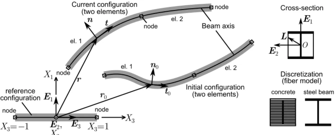
For the 2D case, due to the inherent slenderness of beam-columns failing in global flexural buckling, the Euler-Bernoulli assumption may be adopted. This assumption is particularly attractive, since shear locking is avoided and uniaxial material laws may be employed. A purely displacement-based finite element naturally suffers from membrane locking, but this pathology can be easily solved using reduced integration. A suitable naturally curved two-node cubic (Hermitian) finite element, detailed in (Gonçalves 2018), is employed in this paper. The kinematics are described in Fig. 1, where r is the position vector of the beam axis and t, n are the corresponding tangent and normal vectors, respectively. The initial (curved) configuration of each element is obtained from the coordinates of four points along its axis, making it possible to model, quite easy, complex geometries. Continuity of the slopes at nodes connecting two elements is enforced through a single Lagrange multiplier equation. The element is quite easy to implement, since all relevant expressions are provided in matrix form in (Gonçalves 2018). For instance, the internal virtual work is simply given by
𝛿𝑊𝑖𝑛𝑡 = − ∫ [ 𝛿𝒓̂′𝛿𝒓̂′′] 𝑇 [𝒕 + 𝑋1(𝟏−2𝒕𝒕𝑇)𝑬̃2𝒓′′ ‖𝒓′‖2 −𝑋1𝒏/‖𝒓′‖ ] 𝜎 d𝑉 𝑉 , (1)
where 𝒓̂ = 𝒓 − 𝒓0, 1 is the 33 identity matrix, V is the beam volume at the reference configuration, 𝜎 is the longitudinal normal stress and 𝒂̃ is an anti-symmetric matrix whose axial vector is 𝒂. For material nonlinearity, the cross-section is subdivided into fibers (see Fig. 1) pertaining to each material, where a suitable constitutive law is specified in each one (plasticity, cracking/crushing, etc.). The numerical examples presented in (Gonçalves 2018) demonstrate that the element is very efficient and provides accurate results in a wide range of cases. One of such examples is discussed in section 3.1
Figure 1: Kinematic description of a 2-element assembly and cross-section discretization.
In this paper, the element is further endowed with residual strains in the steel section. These strains are obtained from the residual stress pattern and are added to the compatible strains.
2.2 The 3D case
The spatial case is significantly more complex, since the cross-section rotation becomes independent of the beam axis tangent, even in a Kirchhoff-like formulation (no shear deformation), due to the torsional DOF. Although Kirchhoff formulations including warping torsion are already available (see, e.g., Manta & Gonçalves 2016), the formulation becomes significantly more complex than the standard geometrically exact Timoshenko-like formulation including warping (Simo & Vu-Quoc 1991). In the present paper, a two-node element is employed, which is quite similar to that proposed by Gruttmann et al. (2000), although in the present case (i) the cross-section rotation tensor is parameterized using an interpolation of the rotation vector instead of an interpolation of the basis vectors of the end nodes, and (ii) a thin-walled description is adopted, meaning that the stress/strain components may be divided into bending and membrane components and secondary (through-thickness) warping becomes a function of the rotation about the shear centre, using Kirchhoff’s thin-plate assumption (Gonçalves 2016). With respect to the formulation proposed in (Gonçalves 2016), which is based on a shell-like stress resultant approach, the formulation employed in the present paper (i) relies on a standard stress/strain approach and through-thickness integration (which is more accurate at the expense of some computational efficiency), (ii) allows for arbitrary initial configurations and (iii) can include residual stresses, as in the 2D finite element case.
The independent kinematic parameters involve the position vector of an arbitrary cross-section centre C, 𝒓 = 𝒓(𝑋3), the cross-section rotation vector 𝜽 = 𝜽(𝑋3) and the amplitude of the
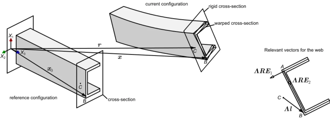
torsion-related warping function 𝑝 = 𝑝(𝑋3). The kinematic description of each cross-section wall is therefore given by (see Fig. 2, which displays all vectors for a given point B located in the web)
𝒙 = 𝒓 + 𝚲𝒍,
Figure 2: Reference and current configurations of a thin-walled beam.
where 𝚲 = 𝚲(𝜽) is the cross-section rotation tensor, 𝑳̅𝐴 is a bi-dimensional vector (in the cross-section plane) that references the “origin” A of each wall mid-line, 𝑹 is each wall “local” rotation tensor about A, rotating the base vectors so that 𝚲𝑹𝑬1 and 𝚲𝑹𝑬2 define the through-thickness and
wall mid-line directions, respectively, 𝜔̅ = 𝜔̅(𝑋2) is the cross-section wall mid-line warping function and 𝜓 = 𝜓(𝑋2) is the slope of the through-thickness warping function. This leads to the
Green-Lagrange strain components 𝐸33 =12(𝒈3𝑀 ⋅ 𝒈3𝑀− 1) + 𝑋1(𝜓𝑝′− 𝐾2), 2𝐸23 = 𝒈2𝑀 ⋅ 𝒈 3 𝑀+ 𝑋 1(𝑝 + 𝐾3), 2𝐸13= 𝛤1+ 𝜓(𝑝 − 𝐾3), (3) with 𝒈2𝑀 = 𝑬 2+ 𝑝𝜔̅,2𝑬3, 𝒈3𝑀 = 𝚪 + 𝑬 3+ 𝑲 × (𝑹𝑇𝑳̅𝐴+ 𝑋2𝑬2+ 𝑝𝜔̅𝑬3) + 𝑝′𝜔̅𝑬3, 𝚪 = (𝚲̂𝑹)𝑇𝒓′− 𝑬 3, 𝑲̃ = (𝚲̂𝑹)𝑇(𝚲̂𝑹)′, (4)
where, 𝚪 and 𝑲̃ are strain measures that quantify extension/shearing and curvature, respectively, 𝚲̂ = 𝚲̂(𝜽̂) is the rotation tensor between the initial (possibly rotated with respect to the reference configuration) and current configurations (𝜽̂ is the corresponding rotation vector).
The equilibrium equations are written in terms of the Green-Lagrange strains and the corresponding work-conjugate second Piola-Kirchhoff stresses. Details of the matrix equations for the implementation of the finite element are provided in (Gonçalves 2016), whereas the auxiliary matrices are fully given in (Gonçalves et al. 2010).
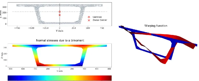
To calculate the mid-line warping function, an in-house Python application was developed which relies on a 4-node finite element discretization of the cross-section. Although this application can
handle arbitrary cross-sections, as shown in Fig. 3, for the proposed two-node beam finite element only the warping displacements of the mid-line are retained, since the through-thickness component 𝜓 can be calculated using Kirchhoff’s thin plate assumption.
Figure 3: Torsion-warping function and normal stresses due to a bi-moment for a box girder bridge cross-section.
3. Validation examples
3.1 The 2D case
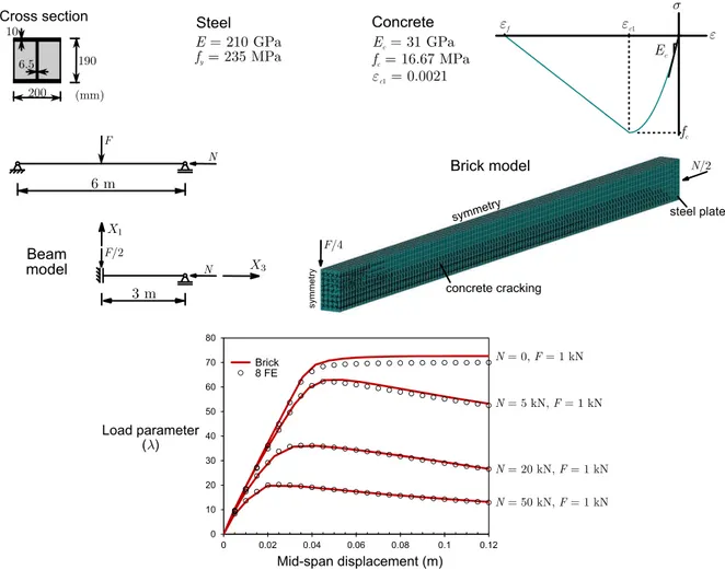
Several examples are already presented in Gonçalves (2018) and therefore a single one is shown in this paper. The example concerns the partially concrete encased steel I-section beam-column depicted in Fig. 4. An elastic-perfectly plastic material law is adopted for steel and the concrete law has no tensile strength and a mesh-adjusted softening modulus, to mitigate mesh-dependency problems, meaning that the final strain (for null stresses) is given by
𝜀𝑓= 𝜀𝑐1−𝐸𝑓𝑐 𝑐+
𝑑̅
𝐿𝑒, (5)
where 𝐿𝑒 is the finite element length, the 𝑑̅ parameter must be calibrated, and the remaining parameters are given in Fig. 4 (all values are assumed positive). In this particular example the results are not strongly affected by the 𝑑̅ value and only for 𝑑̅ < 0.01 m some differences appear, after the peak load. For this reason, the cross-section width was adopted for 𝑑̅. From zero to the peak load 𝑓𝑐, the Eurocode 2 (CEN 2004a) law is adopted and unloading is assumed elastic. The cross-section is discretized using 1 fiber for each steel flange and 8 fibers for the steel web and concrete encasement. Due to symmetry, only half of the beam is modelled.
For comparison purposes, results obtained using 3D brick elements are presented, calculated with ATENA (Cervenka et al. 2013), using the CC3DNonLinCementitious material law for concrete, with 𝐸𝑐 and 𝑓𝑐 given in Fig. 4, plus the program default values for C25/30 concrete with design
values (a Poisson ratio = 0.2 and a tensile strength of 1.2 MPa). Due to the double symmetry, only one quarter of the beam is modelled. Three refinement levels are considered (24, 47 and 714 elements in the concrete cross-section). Since the results for the latter two are virtually
similar, only those of the moderately refined model are shown in the figure. It should be mentioned that a steel plate is placed at the end cross-section, to apply an axial force without introducing stress concentrations.
The graph in the bottom of Fig. 4 shows the load-deflection curves obtained with the proposed geometrically exact beam element (with 8 finite elements) and the moderately refined brick model. An excellent match is found, particularly for higher compression forces. However, the computation times are much different. With an Intel Core i7 CPU @ 2.10 GHz processor, the N = 0 full load-displacement path is obtained in less than 5 seconds in a MATLAB (2010) implementation of the proposed element, whereas the brick model run time is more than 3 hours.
Figure 4: Partially encased steel-concrete composite beam-columns.
3.2 The 3D case
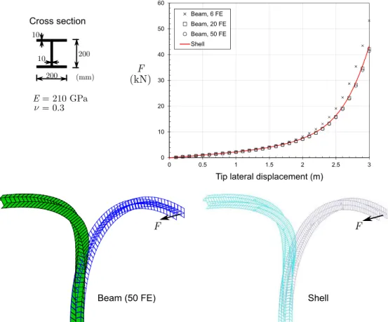
The first example concerns the 6-meter length 90º elastic curved cantilever, as displayed in Fig. 5, and highlights the ability of the proposed 3D geometrically exact beam element to deal with curved geometries and the associated complex torsion-warping transmission. The built-in support prevents all displacements, including warping. Since an elastic material behavior is assumed, for the proposed beam element, cross-section integration is carried out with 2/3 Gauss points along the thickness/mid-line directions, respectively. The graph in the figure shows the load-displacement curves obtained with the present finite element and a MITC-4 shell finite element model, analyzed using ADINA (Bathe, 2017). The figure also shows the deformed configurations
obtained for the beam and shell models, for a 3-meter lateral displacement of the tip. It is concluded that the present element leads to accurate results with only 20 elements (using 50 elements leads to very small changes).
Figure 5: 90º cantilever beam subjected to out-of-plane loading.
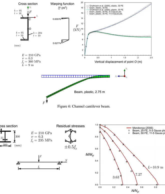
The second example was initially proposed in (Gruttmann et al. 2000) and consist of a 9-meter channel section cantilever steel beam (see Fig. 6) subjected to a concentrated force acting at the free end section, away from the shear centre. The graph in the figure compares the results obtained with the proposed beam finite element with those of the original paper, which were obtained with a two-node beam finite element. The same discretization is employed in both cases (30 finite elements). The results for the elastic case match very well with only 2/3 Gauss points along the thickness/mid-line of each wall, respectively. For the elastic-perfectly plastic material, the integration needs to be increased, but using 5/3 Gauss points already leads to excellent results throughout the displacement range considered.
Finally, collapse loads for simply supported (fork supports) I-section steel beam columns loaded as shown in Fig. 7 are calculated. This example was originally analyzed by Mendonça (2006), using ABAQUS, with 50 two-node B31OS (two-node beam) elements having 49 cross-section integration points in each wall mid-line. Besides a lateral and vertical bow imperfection equal to
L/1000, residual stresses are also introduced, with the pattern displayed in the figure. The graph
makes it possible to compare the results obtained by Mendonça with those provided by the proposed finite element, using two integration/discretization schemes. Small differences are obtained with the two integration/discretization schemes (approximately 2%, meaning that
neither of them always furnishes the lowest loads). Small differences with respect to the results obtained by Mendonça (2006) are also obtained, although the latter correspond to slightly higher collapse loads, particularly for the uniformly compressed case, where a difference of almost 6% is obtained for the smallest member (L = 3.63 m).
Figure 6: Channel cantilever beam.
4. Applications
4.1 Buckling of concrete encased steel I-section beam-columns
This section presents the results of a parametric study concerning the application of the 2D geometrically exact Euler-Bernoulli finite element to assess the buckling (collapse) behavior of partially and fully concrete encased steel I-section beam-columns.
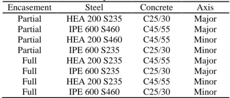
The buckling behavior of concrete encased steel I-section columns was addressed in (Gonçalves & Carvalho 2014), where it was concluded that the Eurocode 4 so-called “simplified method”, which relies on equivalent imperfections and moment amplification, can lead to buckling resistances much lower than those obtained using the European column buckling curves, with differences reaching up to 64% for fully concrete encased columns buckling about the weak axis. In this initial investigation, a group of eight cross-sections (the ones that led to the highest/lowest differences between the simplified method and the buckling curves), indicated in Table 1, was further analyzed using a 2D geometrically exact beam finite element and following the Eurocode 4 “general method”. In this table, it is implicitly assumed that the fully encased sections have the maximum concrete cover allowed in EC4, and the Eurocode notation for the material designation is employed. It was concluded that, if design values of the concrete parameters are used and, simultaneously, an “exact” equivalent imperfection is employed, the buckling resistance becomes closer to that provided by the buckling curves. This “exact” equivalent imperfection is obtained by matching the buckling resistance given by the simplified method and the buckling curves, and is given by 𝑒0 =𝛼𝑀𝑀𝑝𝑙,𝑁,𝑅𝑑 𝜒𝑁𝑝𝑙,𝑅𝑑 (1 + 𝜒𝑁𝑝𝑙,𝑅𝑑 𝑁𝑐𝑟,𝐼𝐼 ), (6)
where the reduction factor 𝛼𝑀 equals 0.9 for steel grades S235 to S355 and 0.8 for S420 and S460
according to EC4, to account for the fact that rectangular stress block theory for calculating the cross-section resistance overestimates the bending capacity (see, e.g., Johnson & Anderson, 2004), 𝜒 is the reduction factor for the appropriate buckling curve, 𝑁𝑝𝑙,𝑅𝑑 is the design value of the section plastic resistance to compressive axial force, 𝑀𝑝𝑙,𝑁,𝑅𝑑 is the design value of the plastic resistance
moment for 𝑁 = 𝜒𝑁𝑝𝑙,𝑅𝑑 and 𝑁𝑐𝑟,𝐼𝐼 is the critical bifurcation axial load, calculated using an effective cross-section flexural stiffness.
Table 1: Composite cross-sections
Encasement Steel Concrete Axis Partial HEA 200 S235 C25/30 Major Partial IPE 600 S460 C45/55 Major Partial HEA 200 S460 C45/55 Minor Partial IPE 600 S235 C25/30 Minor Full HEA 200 S235 C45/55 Major Full IPE 600 S235 C25/30 Major Full HEA 200 S235 C45/55 Minor Full IPE 600 S460 C25/30 Minor
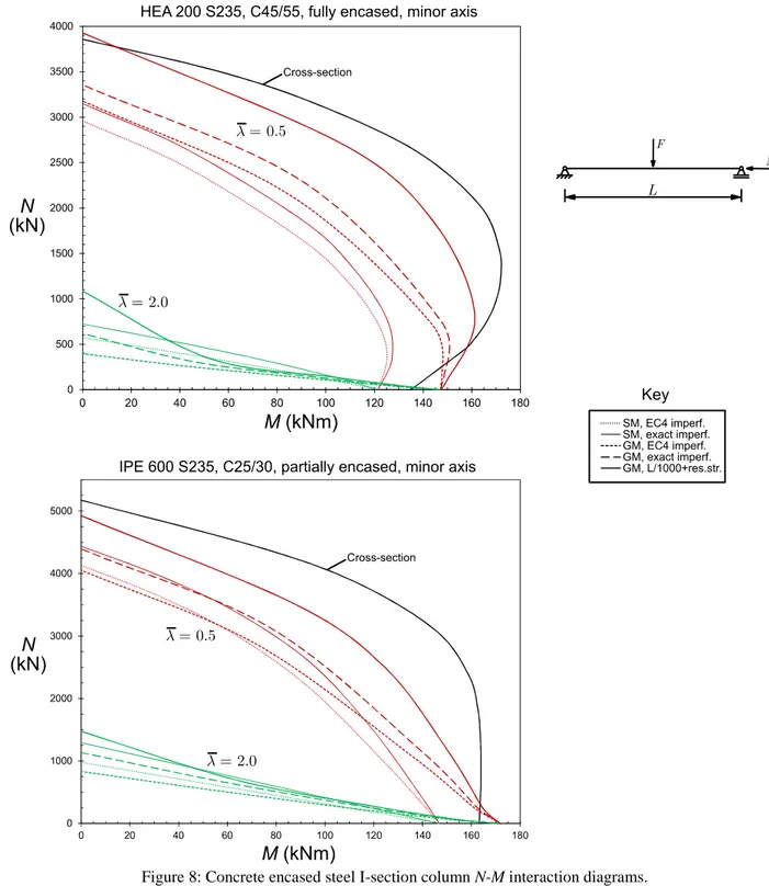
In the present paper, the previous study (concerning the sections in Table 1) is extended by considering simply supported members loaded by combinations of a mid-span transverse force F and an axial force, in order to obtain the complete axial force-moment (N-M) interaction diagram.
Several methods are employed: (i) the EC4 simplified method (SM) and (ii) the EC4 general method (GM) using design values of the material parameters and either equivalent imperfections or a bow imperfection equal to L/1000 plus residual stresses in the steel section. For the equivalent imperfections, both the EC4 values (L/200 for major axis bending and L/150 for minor axis bending) and the “exact” imperfection are considered. In all cases, only in-plane behavior is allowed. In addition, for each section, four slenderness values are analyzed (0,5, 1.0, 1.5 and 2.0). For each analysis type, five points of the N-M interaction diagram were calculated, totaling 845=160 points. For the GM, the proposed 2D geometrically exact beam element was employed. Since three imperfection types were considered, 1603=480 finite element analyses were carried out.
Two typical diagrams (out of the complete eight, each one for each of the cross-sections in Table 1) are displayed in Fig. 8, where the cross-section plastic resistance curve is plotted against the results obtained with the various analysis types considered, but only for the highest and lowest slenderness values for improved readability. The complete set of results makes it possible to draw the following conclusions:
First, concerning the resistance to compression (M=0), it is recalled that the SM curves with the “exact” imperfection lead to resistances coincident with those obtained with the buckling curves and thus can be taken for reference. Taking these values for reference, it is observed that the imperfection type significantly influences the results. As already concluded by Gonçalves & Carvalho (2014), the EC4 imperfection is on the conservative side; it is now further concluded that using L/1000 and residual stresses leads to a higher resistance, as much as 50% above the buckling curve resistance.
Consider now the resistance to bending (N=0). With the GM, the resistance is higher than that given by the cross-section resistance and considerably higher than that given by the SM, which employs a reduction factor M to account for the fact that a cross-section
resistance calculated using rectangular stress blocks overestimates the bending capacity. It is therefore quite surprising to observe that the GM does not predict a decrease of the bending resistance with respect to rectangular stress block theory – this may indicate that a more refined concrete material modeling for the softening branch may be necessary in the FE analyses.
A higher axial capacity with respect to the cross-section curve (occurring in the first graph for the lower slenderness value and the GM with L/1000 plus residual stresses) is obtained. This is due to the fact that, for the calculation of the cross-section curve, the concrete maximum compressive stress is reduced by 15%, whereas in the GM analyses no such limitation considered.
Although not shown in the graphs, it was found that if the abscissa of a GM curve obtained with the “exact” imperfections is multiplied by 1(1M)M/Mpl, the curve becomes quite
close to that obtained with the SM with “exact” imperfections.
Although these results show that the GM can be effectively employed to obtain N-M interaction diagrams similar to those provided by the SM, it is also true that further investigations are necessary in order to verify whether it is possible to define more appropriate (i) geometric imperfections, to be used in conjunction with residual stresses, and (ii) concrete material models, namely for the softening (post peak) part.
Figure 8: Concrete encased steel I-section column N-M interaction diagrams.
4.2 Lateral-torsional buckling of wide flange sections
In the particular case of Eurocode 3, the provisions for lateral-torsional buckling of beams have been under significant scrutiny over the last years. Besides the evident change in the code provisions from the ENV to the EN version of the code (CEN 1992, 2005), new research is still being published to improve the current formulas (e.g., Taras & Greiner 2010).
In this section, the proposed 3D geometrically exact beam finite element is employed to investigate the buckling and post-buckling behavior of wide flange I-section steel beams failing by lateral-torsional buckling. The standard benchmark case of simply supported beams (with “fork” supports) is considered in all examples.
If the simply supported beam is subjected to uniform bending, the effects of pre-buckling deflections can be allowed for by using (Pi & Trahair, 1992)
𝑀𝑐𝑟 =
√𝜋2𝐸𝐼𝑦
𝐿2 (𝐺𝐽+𝜋2𝐸𝐼𝑤𝐿2 ) √(1−𝐼𝑦𝐼𝑥)(1−(𝐺𝐽+𝜋2𝐸𝐼𝑤𝐿2 )/2𝐸𝐼𝑥)
, (7)
where the numerator is the critical buckling moment obtained from a standard linear stability analysis (LSA), that discards the effects of pre-buckling deflections. Clearly, as the minor-to-major axis second moment of area ratio Iy/Ix increases, the critical moment also increases and becomes
infinite if Iy = Ix.
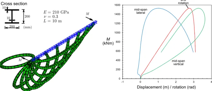
The beam shown in Fig. 9 is analyzed first. In this case the critical buckling moment obtained in a LSA equals 70.8 kNm. However, using Eq. (7) one obtains instead 86.9 kNm. With the proposed 3D beam finite element, the bifurcation load can be calculated by assuming a perfectly straight member and inspecting whether the tangent stiffness matrix at equilibrium has negative eigenvalues. With a discretization into 30 equal-length finite elements, the obtained critical moment equals 86.1 kNm, which falls less than 1% within the result given by Eq. (7).
The post-buckling path can be traced by introducing a geometric imperfection. In the present case a lateral 0.01 m amplitude sinusoidal imperfection was introduced, and the results are displayed in Fig. 9. A highly stable post-buckling path is obtained, until a maximum is reached at very high loads. At the final loading considered, the beam closes in a single loop, as shown in the figure. It is quite interesting to observe that, at large displacements, the mid-span horizontal displacement changes sign and the vertical displacement decreases as the loop rotates with respect to the beam initial axis.
Realistic buckling (collapse) loads can be calculated by including steel plasticity, residual stresses and a lateral sinusoidal imperfection of amplitude equal to L/1000. The elastic and elastoplastic load-displacement paths are shown in Fig. 10 (the elastic path obviously corresponds to that displayed in the graph of Fig. 9). The maximum moment obtained with the proposed beam finite element equals 60.6 kNm, whereas with Eurocode 3 one obtains 54.9 kNm, using the “general case” of clause 6.3.2.2, and 60.5 kNm using the “special method” of clause 6.3.2.3. Such differences between the two methods of EC3 are to be expected and were already reported in the literature (see, e.g., Taras & Greiner, 2010). Nevertheless, the code furnishes buckling loads which are very close to that obtained with the proposed finite element.
Figure 9: Post-buckling of a wide flange I-section beam.
Figure 10: Buckling and collapse of a wide flange I-section beam.
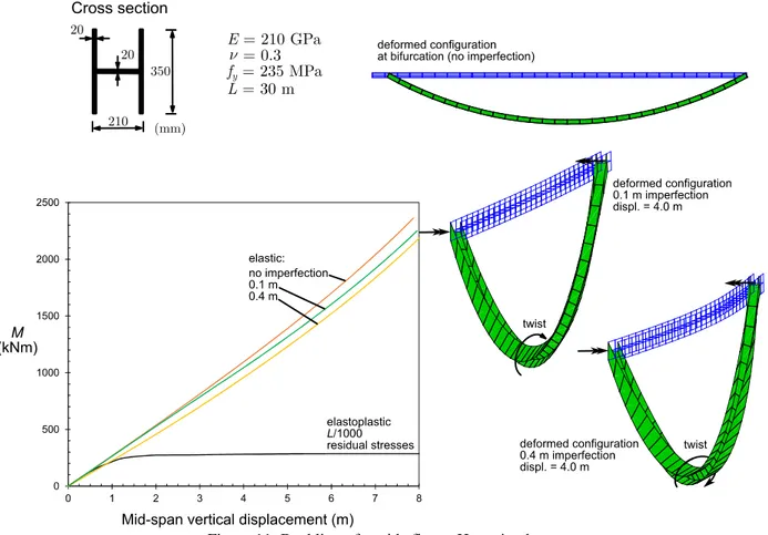
Since Eq. (7) reveals that the critical bifurcation moment increases as Iy/Ix increases, a wide flange
compact (class 1 according to EC3) H section is now analyzed, having the geometry and material parameters indicated in Fig. 11. The minor axis is parallel to the flanges and Iy/Ix = 0.944, which
is considerably high. For a 30 meter simply supported beam under uniform moment, the LSA critical bifurcation moment equals 245 kNm, whereas that obtained with Eq. (7) is significantly higher, 1037 kNm. A finite element analysis with 30 elements retrieves a critical moment of 1041 kNm, which is remarkably close to that of Eq. (7). The deformed configuration shown in the top of Fig. 11 displays the deformed configuration at bifurcation, evidencing very large displacements. Fig. 11 also shows a graph with elastic and elastoplastic post-buckling load-displacement paths. It is immediately noted that the elastic load-displacement curves with imperfections (a lateral sinusoidal imperfection is introduced) are almost linear and do not display typical post-buckling shapes (a sudden increase of displacements is not observed). This is due to the fact that Iy/Ix 1,
meaning that there is no significant bending stiffness difference when torsion occurs due to buckling. This torsion is obviously present when imperfections are introduced in the model, as shown in the deformed configurations displayed in the figure. Naturally, the twist of the mid-span cross-section is higher for the highest imperfection.
Figure 11: Buckling of a wide flange H-section beam.
The elastoplastic load-displacement path plotted in the graph of Fig. 11 was obtained with a horizontal sinusoidal imperfection of amplitude equal to L/1000 and a residual stress pattern like that employed in previous cases (0.5fy). This curve displays a long horizontal plateau and a
maximum moment of (i) 275.3 kNm, obtained with 5 integration points along the wall mid-lines, and (ii) 286.5 kNm, using 11 points, which is almost coincident with the full cross-section plastic moment, 291.8 kNm and thus the reduction factor for lateral-torsional buckling equals 0.982 1 (it is difficult to attain the full plastic moment for this cross-section because the neutral axis coincides with the web mid-line). If the imperfection amplitude is doubled, the results are virtually unchanged (not shown in the graph).
Using Eurocode 3 with the critical moment obtained from a LSA yields a normalized lateral-torsional slenderness 𝜆̅𝐿𝑇 = 1.092, which leads to a reduction factor of 0.602 for the “general case”,
with curve a, and 0.644 for the “special method”, with curve b. Clearly, these predictions fall too much on the conservative side. If the critical moment is calculated taking into consideration the pre-buckling deflections, the slenderness decreases to 0.529 and one obtains 0.915 and 0.948 for
the “general case” and the “special method”, respectively, values which are much more accurate, albeit also somewhat conservative.
Clearly the EC3 approach (with a LSA-based slenderness) underestimates the lateral-torsional buckling resistance in this particular case. However, it should be noted that dividing the maximum FE moment (286.5 kNm) by 1.5 yields 191 kNm, which corresponds to a mid-span vertical displacement of approximately 0.85 m (L/35). This indicates that serviceability will govern the safety checking of the beam, rather than the buckling ultimate limit state.
If the beam length is varied to increase the slenderness, the buckling (collapse) load does not change significantly and always occurs for very large displacements. Even for 𝜆̅𝐿𝑇 = 2.485, calculated with a LSA, the collapse load equals 281.6 kNm and is reached when the beam almost forms a loop.
Consider now a 25-meter span beam with a cross-section with slightly reduced flanges (see Fig. 12), such that the principal axes are rotated by 90º, but with a Iy/Ix ratio similar to that of the
previous example (0.923 in the present case). The results are similar to those obtained in the previous case. The elastic results are analyzed first. Without pre-buckling deflections (LSA), the critical bifurcation moment is 238.9 kNm, whereas with Eq. (7) one obtains 863.8 kNm, which is in very good agreement with the result obtained with a finite element analysis using 30 elements (859.3 kNm). The load-displacement curves with imperfections are once more virtually linear and do not display a typical post-buckling path shape, even though torsion does occur when imperfections are introduced in the model, as shown in the figure, with a higher twist of the mid-span cross-section naturally emerging for the highest imperfection.
For the elastoplastic case, the load-displacement path displays a long horizontal plateau as in the previous example, but a local maximum of 231.2 kNm is now obtained for a vertical displacement of approximately 1 m, corresponding to a buckling reduction factor of 0.791 and virtually coinciding with the minor axis plastic moment (230 kNm). With Eurocode 3 and a critical moment obtained from a LSA one obtains 𝜆̅𝐿𝑇 = 1.106, which leads once more to conservative reduction factors: 0.592 for the “general case”, with curve a, and 0.635 for the “special method”, with curve
b. If the critical moment is calculated considering the pre-buckling deflections, the slenderness
decreases to 0.583 and the reduction factors are now on the unconservative side unless curve c is used within the “general case” (0.795, only slightly unconservative); for the “special method” not even curve d furnishes satisfactory results (0.849).
Once more the EC3 approach (with a LSA-based slenderness) underestimates the lateral-torsional buckling resistance. However, dividing the maximum FE analysis moment (231.2 kNm) by 1.5 yields 115.6 kNm and corresponds to a mid-span vertical displacement of approximately 0.4 m (L/62.5), making it possible to conclude that serviceability will generally govern the safety checking of the beam.
Figure 12: Buckling of a wide flange I-section beam.
Finally, the effect of load height is analyzed. Consider that the previous 25-span beam is loaded instead by a concentrated vertical force, applied at mid-span. The critical moment and maximum (collapse) moments are displayed in Table 2, where the force is either applied at the shear center or the top flange-web intersection. The maximum moments obtained from the finite element analyses were calculated by multiplying the maximum force by the span length (25 m) and dividing the result by four, which is only valid for small displacements and hence the resulting moments appear higher than the minor axis plastic moment.
The results in Table 2 show that the critical load obtained considering pre-buckling deflections is again much higher than that retrieved from a LSA (however in this case Eq. (7) is not valid). Although not shown, for both loading cases the elastic load-displacement paths with imperfections are once more almost linear. Concerning the elastoplastic results, the EC3 predictions fall once more on the conservative side, although in this case the differences are smaller than those obtained for uniform moment. If the pre-buckling deflections are considered for the calculation of the slenderness, the EC3 results become once more on the unsafe side except if curve d is used together with the “general case” (0.875 for shear center loading and 0.814 for top flange loading).
Table 2: Effect of load height in the buckling of a wide flange I-section beam (units in kNm) Loading Mcr LSA Mcr FE Mmax FE L/1000+res.str. Mmax EC3 “GC” a Mmax EC3 “SM” b Shear center 320.6 1283.1 257.2 (0.880) 228.8 (0.783) 238.7 (0.817) Top flange 295.1 896.3 253.4 (0.867) 218.8 (0.748) 229.8 (0.786)
It is recalled that the Eurocode 3 buckling curves were calibrated from a slenderness which is calculated using a critical moment without the effect of the pre-buckling deflections. Hence, the buckling curves already allow, to some extent, for the effect of pre-buckling deflections. However, it is also true that, for standard I and H cross-sections (those used to calibrate the buckling curves), the Iy/Ix ratio is rather small and thus the effect of pre-buckling deflections is limited. For
cross-sections with high Iy/Ix ratios, the results presented herein show that the lateral-torsional resistance
can be much higher than that predicted by Eurocode 3. 5. Concluding remarks
This paper aimed at showing that geometrically exact beam finite elements can be accurately and efficiently employed to assess the buckling and post-buckling behavior of steel and steel-concrete beam-columns. In particular, the paper aimed at contributing for a more widespread use of these elements in the context of advanced structural analyses. Besides presenting a few validation examples, two applications were presented and discussed in detail:
First, the buckling behavior of concrete encased steel I-section beam-columns was examined. The results showed that finite element-based analyses can be effectively employed to obtain N-M interaction diagrams similar to those provided by the Simplified Method of Eurocode 4, but it was also demonstrated that further investigation is necessary to define more appropriate (i) geometric imperfections, to be used in conjunction with residual stresses, and (ii) concrete material models.
Then, the lateral torsional buckling of wide flange steel I-section beams was investigated. For cross-sections with high Iy/Ix ratios, atypical post-buckling paths are obtained and
bifurcation occurs for large displacements. The results presented herein show that the lateral-torsional resistance can be much higher than that predicted by the Eurocode 3 lateral-torsional buckling provisions.
One final word to mention that work is currently under way to provide appropriate solutions for the problems raised above.
References
CEN (1992). ENV 1993-1-1 Eurocode 3: Design of steel structures – Part 1-1: General rules and rules for buildings. Brussels: CEN.
CEN (2004a). EN 1992-1-1 Eurocode 2: Design of concrete structures – Part 1-1: General rules and rules for
buildings. Brussels: CEN.
CEN (2004b). EN 1994-1-1 Eurocode 4: Design of composite steel and concrete structures – Part 1-1: General rules
and rules for buildings. Brussels: CEN.
CEN (2005). EN 1993-1-1 Eurocode 3: Design of steel structures – Part 1-1: General rules and rules for buildings. Brussels: CEN.
Cervenka, V. Jendele, L., Cervenka, J. (2013) ATENA 3D Program Documentation, Cervenka Consulting.
Gonçalves, R., Carvalho, J. (2014). “An efficient geometrically exact beam element for composite columns and its application to concrete encased steel I-sections.” Engineering Structures, 75 213-224.
Gonçalves, R., Ritto-Corrêa, M., Camotim, D. (2010). “A large displacement and finite rotation thin-walled beam formulation including cross-section deformation.” Computer Methods in Applied Mechanics and Engineering, 199 (23-24) 1627-1643.
Gonçalves, R. (2018). “An improved geometrically exact planar beam finite element for curved steel and steel-concrete composite beams.” Thin-Walled Structures, 123 492-500.
Gruttmann, F., Sauer, R., Wagner, W. (2000). “Theory and numerics of three-dimensional beams with elastoplastic material behavior.” International Journal for Numerical Methods in Engineering, 48 1675-1702.
Johnson, R., Anderson, M. (2004). Designers’ Guide to EN 1994-1-1. Eurocode 4: Design of composite steel and
Manta, D., Gonçalves, R. (2016). “A geometrically exact Kirchhoff beam model including torsion warping.”
Computers and Structures, 177 192-203.
MATLAB (2010), version 7.10.0 (R2010a), The MathWorks Inc., Massachusetts.
Mendonça, P. (2006). Design of beam-columns through the Eurocode interaction equations: fundamentals, validation
and application. Master Thesis, Instituto Superior Técnico, Lisbon University.
Pi, Y., Trahair, N. (1993). “Prebuckling deflections and lateral buckling. II: Applications.” Journal of Structural
Engineering, 118 (11) 2967-2985.
Reissner, E. (1972). “On one-dimensional finite-strain beam theory: the plane problem.” Journal of Applied
Mathematics and Physics (ZAMP), 23 795-804.
Simo, J. (1985). “A finite strain beam formulation. The three-dimensional dynamic problem, Part I.” Computer
Methods in Applied Mechanics and Engineering, 49 55-70.
Simo, J., Vu-Quoc, L., (1991). “A geometrically-exact rod model incorporating shear and torsion-warping deformation.” International Journal of Solids and Structures, 27 (3) 371-393.
Taras, A. (2016). “Derivation of DSM-type resistance functions for in-plane global buckling of steel beam-columns.”
Journal of Constructional Steel Research, 125 95-113.
Taras, A., Greiner, R., (2010). “New design curves for lateral-torsional buckling. Proposal based on a consistent derivation.” Journal of Constructional Steel Research, 66 648-663.