DEVELOPMENT OF A MODEL BASED ON VIRTUAL REALITY FOR THE
EVALUATION OF BEHAVIORAL COMPLIANCE WITH WARNINGS AND
WAYFINDING CONTEXTS
Dissertação elaborada com vista à obtenção do Grau de Doutor em Motricidade Humana, na especialidade de Ergonomia
Orientadores
DOUTOR FRANCISCO DOS SANTOS REBELO
DOUTOR FERNANDO JOSÉ CARNEIRO MOREIRA DA SILVA
Júri
Presidente
REITOR DA UNIVERSIDADE DE LISBOA
Vogais
DOUTOR PEDRO MIGUEL FERREIRA MARTINS AREZES
Professor Catedrático – Escola de Engenharia da Universidade do Minho DOUTOR FERNANDO JOSÉ CARNEIRO MOREIRA DA SILVA
Professor Catedrático – Faculdade de Arquitectura da Universidade de Lisboa DOUTOR FRANCISCO DOS SANTOS REBELO
Professor Associado com Agregação – Faculdade de Motricidade Humana da Universidade de Lisboa DOUTORA ISABEL MARIA DO NASCIMENTO LOPES NUNES
Professora Auxiliar – Faculdade de Ciências e Tecnologia da Universidade Nova de Lisboa DOUTOR PAULO IGNACIO NORIEGA PINTO MACHADO
Professor Auxiliar – Faculdade de Motricidade Humana da Universidade de Lisboa DOUTORA ARMINDA DA CONCEIÇÃO DOS SANTOS GUERRA LOPES
Professora Adjunta – Escola Superior de Tecnologia do Instituto Superior de Castelo Branco
LUÍS MIGUEL BOUCINHA TEIXEIRA
2016
This work was only possible thanks to a PhD scholarship granted by the Portuguese Science Foundation (FCT) (SFRH/BD/65216/2009)
Abstract
Virtual Reality (VR) when framed in adequate methodologies, has an ample field of application for Ergonomics and for Design, since it allows to analyze and understand how people interact with simulated situations in Virtual Environments (VEs). As such, it is of extreme importance for research and the practice of Ergonomics, to understand how it is possible to optimize, create, implement and evaluate solutions based in VEs in different contexts, including dangerous ones, in particular those that can place in risk the physical integrity of people. These VEs can be used to study Human Behavior in critical situations, which is important when projecting products and systems that involve dangers to the users that would be difficult to study otherwise.
In this context, this project has as its general objective the study of the factors that influence the development of VEs for VR and in the implementation of solutions (with a focus on software and hardware) that better can correspond to the development of this type of studies, namely in studies of behavioral compliance with warnings and in studies of wayfinding. The methodological proposal described in this document focuses in a User-Centered Design (UCD) perspective, which involved the participation of the users, in the different phases of development of the project. As a result, it were developed and evaluated software and hardware solutions for the understanding and evaluation of the factors associated to the study of Human behavior, namely in behavioral compliance with warnings and in wayfinding contexts.
It was also studied the best solutions for interaction and navigation in VEs, that correspond to high levels of presence, which is a fundamental aspect in behavioral compliance with warnings and wayfinding studies that use VR as a support tool. With this purpose, two navigational interfaces were developed (i.e., Balance Board and Walk-in-Place), also in a UCD perspective, to guarantee a constant cycle of tests and improvement of the implementations among the users. A comparative study was made between these two navigational interfaces and another that is commonly used in studies with VR (i.e., a Joystick). This comparative study was conducted in a context of evaluation of behavioral compliance with warnings and performance variables were analyzed, as well as the levels of presence in the different navigational interfaces. There were no statistically significant differences in the levels of presence or in the behavioral compliance between the three navigational interfaces. However, statistically significant differences were found in several performance variables (e.g., average speed, total distance). Future directions for the research are also discussed.
Resumo
A Realidade Virtual (RV) quando enquadrada em metodologias adequadas, tem um campo de aplicação alargado para a Ergonomia e o Design, visto permitir analisar e compreender como as pessoas interagem com situações simuladas em Ambientes Virtuais (AVs). Desta forma, é de extrema importância para a investigação ou prática da Ergonomia, perceber como se pode optimizar, construir, implementar e avaliar soluções baseadas em AVs em diferentes contextos, incluindo contextos perigosos, particularmente aqueles que podem colocar em risco a integridade física das pessoas. Estes AVs podem ser usados para estudar o comportamento Humano em situações críticas, o que é importante quando se projecta produtos e sistemas que envolvam perigos para os utilizadores que de outra forma seria muito difícil avaliar.
Neste contexto, este projecto tem como objectivo geral o estudo dos factores que influenciam o desenvolvimento de ambientes para Realidade Virtual e na implementação de soluções (com um foco maior no software e hardware) que melhor possam corresponder ao desenvolvimento deste tipo de estudos, nomeadamente em estudos de consonância comportamental com avisos de segurança e estudos de wayfinding. A proposta metodológica descrita neste documento foca-se numa perspectiva de Design Centrado no Utilizador (DCU), que envolveu a participação dos utilizadores, nas várias fases de desenvolvimento do projecto. Como resultado, desenvolveu-se e avaliou-se soluções de software e hardware para a compreensão e avaliação dos factores associados ao estudo do Comportamento Humano, nomeadamente para a consonância comportamental com avisos de segurança e para situações de wayfinding.
Foram também estudadas as melhores soluções para interacção e navegação em AVs, que correspondam a níveis de presença elevados, aspecto fundamental em estudos de consonância comportamental com avisos de segurança e em estudos de wayfinding que usam RV. Com este intuito, foram desenvolvidas duas interfaces de navegação para Realidade Virtual (i.e., Balance Board e Walk-in-Place), também numa perspectiva de DCU, para garantir um constante ciclo de testes e aperfeiçoamento das implementações junto dos utilizadores. Foi realizado um estudo comparativo entre estas duas interfaces de navegação e uma outra que é utilizada mais frequentemente em estudos com RV (i.e., um Joystick). Este estudo comparativo realizou-se num contexto de avaliação da consonância comportamental com avisos de segurança e foram analisadas variáveis de desempenho, assim como os níveis de presença das diferentes interfaces de navegação. Não se observaram diferenças estatisticamente significativas em relação aos níveis de presença nem em relação à consonância comportamental entre as três interfaces de navegação. No entanto, foram encontradas diferenças estatisticamente significativas em várias variáveis de desempenho (e.g., velocidade média, distância percorrida). Também são discutidas as possíveis linhas de investigação de continuação ao trabalho.
Acknowledgements
I would like start by thanking my advisors, Prof. Rebelo and Prof. Moreira da Silva, for their support, availability and guidance to improve this work even further.
I would like to thank Ernesto Filgueiras, Elisângela Pessoa and Emília Duarte for their complete support, guidance, for constantly challenging me and pushing me forward, and in certain occasions, for their faith in me, but most importantly, an enduring friendship that surpasses the work environment. I hope that I was able to reciprocate at the same level. To Paulo Noriega I would like to thank the avid work discussions where I learned much. I would also like to thank Júlia Teles for her invaluable help and patience with me in the data analysis.
I am extremely grateful for the long lasting friendship with André Martins, whom has been always present, supportive, and always open for challenging discussions (work related or otherwise). Thank you for all the passionate discussions which led the project to a better state.
Also, mostly in other capacities, I would like to thank for all the support, friendly discussions, but mostly the strong bonds that were created with several people during this work. They are: Hande Ayanoğlu, Lara Reis, Pedro Júdice, Beste Özcan, Marcela Chávez, Joana Fernandes and Mariana Vital. Thank you all for accompanying me during this path, and hopefully many others to come. I would like to thank especially Carlota Silva for her tremendous support in the last stretch of writing this document.
I would like to thank Tânia Marçalo, João Ribeiro and Geneviève Santorum for their precious help in the data collection and recruiting of participants for the study. I would also like to thank André Figueiredo for his valuable help in the same tasks and for the friendship that grew from it. Also, I would like to thank to all the participants, since without them it wouldn’t be possible to conclude the study.
Most importantly, I would like to thank my mother, ever present, supportive and an unshakable faith in my abilities. Thank you.
Lastly but not least, I would like to thank to everyone that supported me and pushed me harder, in smaller or larger parts, in this small step on the journey of constant learning which is life.
Table of Contents
ABSTRACT ... I RESUMO ... III ACKNOWLEDGEMENTS ... V
CHAPTER I - INTRODUCTION ... 1
1.1VIRTUAL REALITY AND ERGONOMICS RESEARCH ... 4
1.2STRUCTURE OF THE DOCUMENT ... 6
CHAPTER II - MODEL DEVELOPMENT (ERGOVR) ... 7
2.1INTRODUCTION ... 7 2.2METHOD ... 8 2.2.1 Context of use ... 9 2.2.2 Requirements ... 10 a) Specific requirements ...11 2.2.3 Design solutions ... 12 2.2.4 Evaluation ... 13
2.3DESCRIPTION OF THE ERGOVR SYSTEM ... 14
2.3.1 Global view of the system ... 15
2.3.2 Creation of Virtual Environments ... 16
2.3.3 Simulator... 20
a) Global view of the simulator ...20
b) Custom subsystems ...25
c) Currently compatible hardware ...36
2.3.4 LogViewer ... 37
a) Space Exploration Matrices...41
2.4EVALUATION OF ERGOVR ... 44
2.4.1 Behavioral compliance with warnings studies ... 44
2.4.2 Wayfinding studies ... 48
a) Study 1 ...49
b) Study 2 ...50
2.4.3 Other studies ... 51
2.5CONCLUSIONS ... 52
CHAPTER III - NAVIGATIONAL INTERFACES ... 55
3.1INTRODUCTION ... 55
3.1.1 Hypotheses and rationale ... 58
3.1.2 Navigational interfaces ... 59
a) Joystick ...59
b) Balance Board ...60
c) Walk-in-Place ...61
3.2METHOD ... 66
a) Training ...67
b) Simulation...68
3.2.3 Variables ... 72
a) Questionnaire ...73
3.2.4 Sample ... 75
a) Experience with videogames and VR simulators ...76
3.2.5 Apparatus ... 80
3.2.6 Experimental facilities... 81
3.3RESULTS AND DISCUSSION ... 83
3.3.1 Behavioral compliance ... 84
a) Compliance with uncued signs ...85
b) Compliance with cued signs ...85
c) Compliance with exit signs ...86
d) Gender differences...88
3.3.2 Navigational interface performance... 88
a) Duration...89 b) Distance ...92 c) Pauses ...94 d) Average speed ... 101 e) Gender differences ... 105 3.3.3 Sense of presence ... 106 a) Gender differences ... 115 3.3.4 Simulator sickness ... 115 3.4CONCLUSIONS ... 116
CHAPTER IV - FINAL CONCLUSIONS ... 121
4.1FUTURE WORK ... 127
REFERENCES ... 129
ANNEXES ... 139
ANNEX A–CONSENT FORM ... 141
List of Figures
FIGURE 1 - DIAGRAM OF THE METHODOLOGY USED 3
FIGURE 2 - USER-CENTERED DESIGN DIAGRAM. ADAPTED FROM (ISO, 1999). 9
FIGURE 3 - TOP VIEW OF THE VIRTUAL ENVIRONMENT USED FOR THE FIRST PILOT TESTS 13
FIGURE 4 – THE THREE STAGES OF THE ERGOVR'S SYSTEM USE 16
FIGURE 5 - DIAGRAM WITH THE SUBSYSTEMS THAT COMPOSE THE ERGOVR SIMULATOR 21
FIGURE 6 - LOG FILE AND LOGENTRY STRUCTURE 28
FIGURE 7 - THE DIFFERENT TYPES OF ACTION AVAILABLE IN THE EVENTS SYSTEM 31
FIGURE 8 - PRACTICAL EXAMPLE ROOM WITH SOME TRIGGERS AND A BUTTON 34
FIGURE 9 - DEFINITION OF THE EVENTS FOR THE SIMPLE EXAMPLE 35
FIGURE 10 - LOGVIEWER'S GROUP WINDOW WITH AN EXAMPLE 38
FIGURE 11 - LOGVIEWER'S AREAS WINDOW WITH AN EXAMPLE 39
FIGURE 12 - EXAMPLE OF AN EXPORTED IMAGE OF A PARTICIPANT'S PATH 40
FIGURE 13 - LOGVIEWER'S GRID WINDOW 42
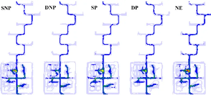
FIGURE 14 - SPACE EXPLORATION MATRICES OF THE VE, PER EXPERIMENTAL CONDITION 43
FIGURE 15 – THRUSTMASTER® USB JOYSTICK (IMAGE OBTAINED FROM THE OFFICIAL WEBSITE) 60 FIGURE 16 - IMAGES OF THE NINTENDO WII BALANCE BOARD. SEEN FROM ABOVE (LEFT) AND SEEN FROM THE
BOTTOM (RIGHT). IMAGES RETRIEVED FROM NINTENDO®’S OFFICIAL WEBSITE AND USER MANUAL. 60
FIGURE 17 - MOVEMENT REPRESENTATION ON THE BALANCE BOARD 61
FIGURE 18 - THE ANGULAR MEASUREMENTS USED TO TRANSLATE THE TRACKED BODY INTO THE MOVEMENT WITHIN THE VE. Α REPRESENTS THE DIFFERENCE BETWEEN THE ROTATION VALUES GIVEN BY THE SENSOR
WHEN THE LEG IS LIFTED. 64
FIGURE 19 - THE GRAPHIC MODEL OF THE TRANSLATED BODY MOVEMENT TRACKED BY THE SENSOR WITH THE TWO AREAS WHICH REPRESENT THE LIFTED (Α) AND REST (Β) POSITION OF THE LEG OF A SPECIFIC
PARTICIPANT (DIMENSIONLESS DATA BECAUSE IT CHANGES PER PARTICIPANT). 64
FIGURE 20 - GENIUS® RING MOUSE INTERACTION DEVICE 65
FIGURE 21 - TOP VIEW OF THE TRAINING VIRTUAL ENVIRONMENT 67
FIGURE 22 - TRAINING ENVIRONMENT'S ROOM WITH THE COLUMN AT ITS CENTER 68
FIGURE 23 - VIEW OF THE POSTERS AND BUTTON ON THE TRAINING ENVIRONMENT 68
FIGURE 24 - ENTRANCE OF THE CAFETERIA WITH THE HORN WARNING AND RESPECTIVE BUTTON 69 FIGURE 25 - CAFETERIA VIEW WITH THE BOARD WITH THE MESSAGE ON THE LEFT AND THE VALVE GAS ON THE
RIGHT SIDE 69
FIGURE 26 - ENTRANCE OF THE WAREHOUSE WITH THE BUTTON REGARDING POLLUTED ATMOSPHERE 70 FIGURE 27 - VIEW OF THE FIRE INSIDE THE WAREHOUSE, WHICH STARTS WHEN THE PARTICIPANT ENTERS THE
WAREHOUSE 70
FIGURE 28 - VIEW OF THE ENTRANCE TO AREA 2 - ESCAPE ROUTES, JUST OUTSIDE THE WAREHOUSE 70
FIGURE 29 - VIEW OF THE FIRST INTERSECTION, WITH THE VISIBLE EXIT SIGN 70
FIGURE 30 - VIEW OF AN INTERSECTION WITH THE LETTER FOR THAT INTERSECTION 71
FIGURE 31 - VIEW OF THE EXIT POINT (END OF THE SIMULATION) 71
FIGURE 32 - TOP VIEW AND SEQUENCE OF EVENTS OF THE VIRTUAL ENVIRONMENT 71
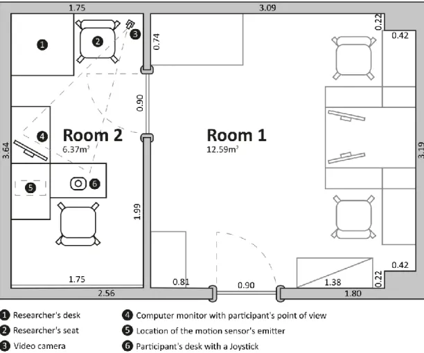
FIGURE 33 - VIRTUAL REALITY PLATFORM FOR NAVIGATIONAL INTERFACES 81
FIGURE 34 - TOP VIEW OF THE EXPERIMENTAL FACILITIES FOR THE JOYSTICK CONDITION (UNITS IN METERS) 82 FIGURE 35 - TOP VIEW OF THE EXPERIMENTAL FACILITIES FOR THE BALANCE BOARD AND WALK-IN-PLACE
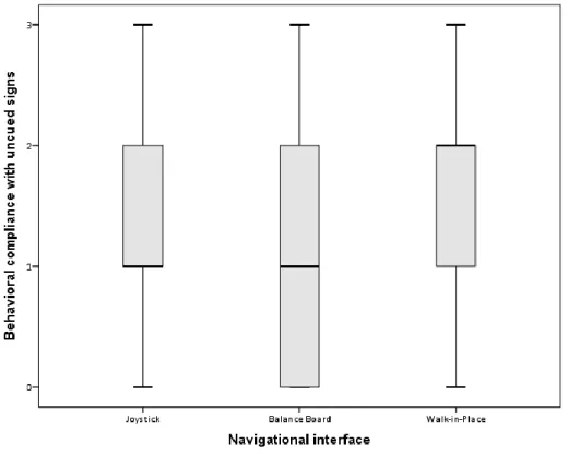
FIGURE 36 - BOXPLOTS FOR THE BEHAVIORAL COMPLIANCE WITH UNCUED SIGNS VARIABLE, ACCORDING TO THE
NAVIGATIONAL INTERFACE 85
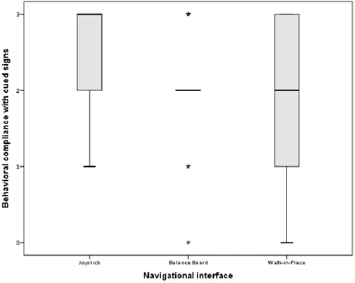
FIGURE 37 - BOXPLOTS FOR THE BEHAVIORAL COMPLIANCE WITH CUED SIGNS VARIABLE, ACCORDING TO THE
NAVIGATIONAL INTERFACE 86
FIGURE 38 - BOXPLOTS FOR THE BEHAVIORAL COMPLIANCE WITH EXIT SIGNS VARIABLE, ACCORDING TO THE
NAVIGATIONAL INTERFACE 87
FIGURE 39 - BOXPLOTS OF THE DURATION OF THE SIMULATION IN AREA 1 - ROOMS, BY EXPERIMENTAL
CONDITION 90
FIGURE 40 - BOXPLOTS OF THE DURATION OF THE SIMULATION IN AREA 2 - ESCAPE ROUTES, BY EXPERIMENTAL
CONDITION 91
FIGURE 41 - BOXPLOTS OF THE DISTANCE TRAVELLED IN THE SIMULATION IN AREA 1 - ROOMS, BY EXPERIMENTAL
CONDITION 93
FIGURE 42 - BOXPLOTS OF THE DISTANCE TRAVELLED IN THE SIMULATION IN AREA 2 - ESCAPE ROUTES, BY
EXPERIMENTAL CONDITION 93
FIGURE 43 - BOXPLOTS OF THE NUMBER OF PAUSES IN AREA 1 - ROOMS, BY EXPERIMENTAL CONDITION 95 FIGURE 44 - BOXPLOTS OF THE NUMBER OF PAUSES IN AREA 2 - ESCAPE ROUTES, BY EXPERIMENTAL CONDITION 96 FIGURE 45 - BOXPLOTS FOR THE MAXIMUM DURATION OF THE PAUSES IN AREA 1, FOR THE DIFFERENT
NAVIGATIONAL INTERFACES 98
FIGURE 46 - BOXPLOTS FOR THE MAXIMUM DURATION OF THE PAUSES IN AREA 2, FOR THE DIFFERENT
NAVIGATIONAL INTERFACES 98
FIGURE 47 - BOXPLOTS FOR THE MEDIAN DURATION OF THE PAUSES IN AREA 1, FOR THE DIFFERENT
NAVIGATIONAL INTERFACES 100
FIGURE 48 - BOXPLOTS FOR THE MEDIAN DURATION OF THE PAUSES IN AREA 2, FOR THE DIFFERENT
NAVIGATIONAL INTERFACES 101
FIGURE 49 - BOXPLOTS FOR THE AVERAGE SPEED IN AREA 1, FOR THE DIFFERENT NAVIGATIONAL INTERFACES 102 FIGURE 50 - BOXPLOTS FOR THE AVERAGE SPEED IN AREA 2, FOR THE DIFFERENT NAVIGATIONAL INTERFACES 103
FIGURE 51 - ESTIMATED MARGINAL MEANS OF AVERAGE SPEED 104
FIGURE 52 - BOXPLOTS FOR THE QUALITY OF SENSORIAL EXPERIENCE FOR EACH OF THE NAVIGATIONAL
INTERFACES 108
FIGURE 53 - BOXPLOTS FOR THE QUALITY OF INTERACTION FOR EACH OF THE NAVIGATIONAL INTERFACES 109 FIGURE 54 - BOXPLOTS FOR THE QUALITY OF INTERACTION FOR THE NAVIGATIONAL INTERFACE FOR EACH OF THE
NAVIGATIONAL INTERFACES 109
FIGURE 55 - BOXPLOTS FOR THE DISTRACTION FACTORS FOR EACH OF THE NAVIGATIONAL INTERFACES 110 FIGURE 56 - BOXPLOTS FOR THE REALISM LEVEL FOR EACH OF THE NAVIGATIONAL INTERFACES 110 FIGURE 57 - BOXPLOTS FOR THE NOTION OF TIME FOR EACH OF THE NAVIGATIONAL INTERFACES 111 FIGURE 58 - BOXPLOTS FOR THE ENJOYMENT FOR EACH OF THE NAVIGATIONAL INTERFACES 111
List of Tables
TABLE 1 - PRESENCE AND ENJOYMENT QUESTIONNAIRE ITEMS 73
TABLE 2 - ANCHOR LABELS FOR THE LIKERT-TYPE QUESTIONS 75
TABLE 3 – SAMPLE’S AGE DESCRIPTIVE STATISTICS, BY EXPERIMENTAL CONDITION 76
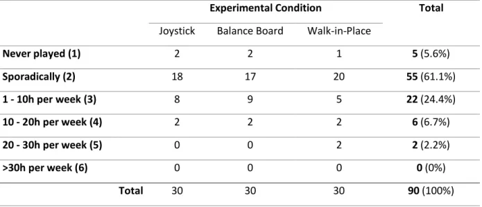
TABLE 4 - SAMPLE DISTRIBUTION REGARDING THE PARTICIPANTS' EXPERIENCE WITH VIDEOGAMES, BY
EXPERIMENTAL CONDITION 77
TABLE 5 - SAMPLE DISTRIBUTION FOR PARTICIPANTS THAT ARE FREQUENT PLAYERS OF ACTION/ADVENTURE
VIDEOGAME 77
TABLE 6 - SAMPLE DISTRIBUTION FOR GAMING PROFILE PREFERENCE FOR FREQUENT PLAYERS 78 TABLE 7 - SAMPLE DISTRIBUTION REGARDING PREVIOUS EXPERIENCE WITH VR SIMULATORS THAT USE VR GLASSES
78 TABLE 8 - SAMPLE DISTRIBUTION REGARDING PREVIOUS EXPERIENCE WITH VR SIMULATORS THAT INVOLVE
PLATFORMS WITH MOTION 79
TABLE 9 - SAMPLE DISTRIBUTION REGARDING PREVIOUS EXPERIENCE WITH VR SIMULATORS THAT INVOLVE BOTH
MODALITIES (VR GLASSES AND PLATFORMS WITH MOTION) 79
TABLE 10 – FREQUENCY OF CORRECT DECISIONS AT THE T-SHAPED INTERSECTIONS, BY EXPERIMENTAL
CONDITIONS 87
TABLE 11 - DESCRIPTIVE STATISTICS FOR THE DURATION VARIABLE, IN THE TWO AREAS (IN SECONDS) 89 TABLE 12 - DESCRIPTIVE STATISTICS FOR THE DISTANCE VARIABLE, IN THE DIFFERENT AREAS (IN METERS) 92 TABLE 13 - DESCRIPTIVE STATISTICS FOR THE NUMBER OF PAUSES VARIABLE, IN THE DIFFERENT AREAS 94 TABLE 14 - DESCRIPTIVE STATISTICS FOR THE MAXIMUM DURATION OF PAUSES IN THE DIFFERENT AREAS 97 TABLE 15 - DESCRIPTIVE STATISTICS FOR THE MEDIAN DURATION OF PAUSES IN THE DIFFERENT AREAS 99 TABLE 16 - DESCRIPTIVE STATISTICS (PRESENTED IN METERS PER SECOND) FOR THE AVERAGE SPEED IN THE
DIFFERENT AREAS 102
TABLE 17 - TWO-WAY MIXED ANOVA AVERAGE (AND STANDARD DEVIATION) FOR THE INTERACTION BETWEEN
THE NAVIGATIONAL INTERFACE AND THE AREA 104
TABLE 18 - SUMMARY OF THE MANN-WHITNEY TEST RESULTS REGARDING GENDER DIFFERENCES FOR THE
PERFORMANCE VARIABLES 106
TABLE 19 - DESCRIPTIVE STATISTICS FOR THE SENSE OF PRESENCE VARIABLES 107
TABLE 20 - CORRELATIONS FOUND FOR THE SENSE OF PRESENCE VARIABLES, GLOBALLY 112
TABLE 21 - CORRELATIONS FOUND FOR THE SENSE OF PRESENCE VARIABLES, FOR THE JOYSTICK 113 TABLE 22 - CORRELATIONS FOUND FOR THE SENSE OF PRESENCE VARIABLES, FOR THE BALANCE BOARD 114 TABLE 23 - CORRELATIONS FOUND FOR THE SENSE OF PRESENCE VARIABLES, FOR THE WALK-IN-PLACE 115
Chapter I - Introduction
This study is carried out in the scope of the use of Virtual Reality (VR) for Ergonomics studies, in the domain of Cognitive Ergonomics to be applied in the optimization of Human interaction in Design proposals.
The International Ergonomics Association (IEA) defines Ergonomics as having three domains of specialization (IEA, 2006): 1) Physical Ergonomics; 2) Cognitive Ergonomics; and 3) Social or Organizational Ergonomics. Physical Ergonomics concerns with the human physical compatibility with the static and dynamic parameters of physical work. Cognitive Ergonomics concerns with the mental processes when relating the human interactions with elements of a system. Social and Organizational Ergonomics concerns with the optimization of work systems (organizational structures, policies, processes).
Since the common denominator of the three domains is Human Behavior, its assessment is considered the golden measure for the evaluation of efficiency of the solutions (e.g., warnings, environments). However, this assessment is complex due to the costs of effort, time, safety, and ethical considerations involved in measuring what people do, without biasing their behavior and offering a realistic situation/context for interaction, with a good balance between internal and ecological validities. This fact has led researchers to choose to measure other variables, other than behavior, in order to test the quality of the solutions (e.g., attention, comprehension) and resort to methods and tools such as questionnaires, self-reports, among others (Duarte, Rebelo, & Wogalter, 2010). In this sense, VR has been considered a methodological tool with the potential to carry out this type of studies, allowing the assessment of human behavior, minimizing or overcoming the majority of the obstacles identified in the so-called “traditional” methodologies, with a reasonable ecological validity (e.g., Blascovich et al., 2002; Duarte et al., 2010).
However, despite recent technological developments, there are not ready-to-use VR solutions that are suitable for this type of studies which enable researchers with an easy customization of variables that they want to evaluate (e.g., behavioral compliance). Furthermore, current systems are not without limitations with some of the most important connected with navigational interfaces which, in many cases, offer navigation forms that are not “natural”, which can jeopardize the validity of the study.
In this regard, the main objective of this study is the determination of the factors that influence VR-based studies and create a VR model, which can be customizable and dedicated to the study of human behavior for Cognitive Ergonomics studies. To achieve this objective, the following specific objectives were defined:
Develop navigational interfaces to use in the VR model and evaluate it for Cognitive Ergonomics studies.
Due to the multidisciplinary nature of VR, it would be impractical to focus in several of the sub disciplines (e.g., hardware, software, interaction strategies, sounds, virtual environments, storytelling, data collection location, variables of the study) with the level of intended and necessary detail and as such, the main focus was given to the software sub discipline. Although the level of expertise regarding the remaining sub disciplines is lower than for the software, the model was developed to be compatible with all of the sub disciplines.
The methodology used for the development of this work is presented in Figure 1. It is divided into three stages.
On Stage 1, the main development of the ErgoVR system took place, which will be further detailed on Chapter II - Model Development (ErgoVR). Initially, from the information gathered from a Literature Analysis and the User’s needs, the definition of requirements took place. From those requirements the development stage ensued, followed a testing stage. These three stages are part of an iterative cycle (i.e., based on a UCD approach), where the requirements and consequently the development stage had some refinements and improvements. When the ErgoVR system was at a stage that was considered to follow the requirements and the tests ran as expected, the first version of ErgoVR was built before entering in Stage 2.
Stage 2 represents the evaluation made of ErgoVR, with two main studies. This evaluation is detailed in topic 2.4 - Evaluation of ErgoVR. The studies focused on the assessment of human behavior in the interaction with warnings (i.e., evaluation of behavioral compliance with warnings) and complex environments (i.e., wayfinding performance evaluation), in everyday and emergency situations. Although not represented in the diagram, some minor changes occurred at this stage which resulted in the second version of the ErgoVR system.
On Stage 3, the development of the Balance Board and Walk-in-Place navigational interfaces and the experimental study to evaluate them for Cognitive Ergonomics studies, takes place. The development approach used was the same as the one for the ErgoVR system, i.e., UCD. This allowed that the development of the interface was accompanied with constant testing and improvements until it was deemed ready for a more complex test. At that point, an experimental study (detailed on Chapter III - Navigational Interfaces) was done. Since one of the main objectives of conducting this study was to evaluate the navigational interface while comparing to other navigational interfaces, on a Cognitive Ergonomics context, an already available Virtual Environment (VE) and scenario was used. The study had a between-subjects design due to the repetition of the task, in the same VE, measuring performance variables which would be affected by the learning effect of if there were repetition. Its focus was on the evaluation of behavior compliance with warnings in an emergency situation. From the development of the Walk-in-Place
interface and the experimental study’s results, the most recent version of the ErgoVR was made. Future work on ErgoVR should continue from this version.
1.1 Virtual Reality and Ergonomics Research
In the literature, Virtual Reality is defined on two main points-of-view that complement each other. One is focused on the concept of VR (e.g., Burdea & Coiffet, 2003), while others focus on the technological side of VR (e.g., Gutierrez, Vexo, & Thalmann, 2008; Steed, 1993).
Burdea and Coiffet (2003) defined VR as a group of three concepts: Interaction, Immersion and Imagination. Interaction is the ability of a VR system to allow interaction with the VE (e.g., holding, moving objects, walking). Immersion is the isolation degree to which the individual is, to the extent of the real world that surrounds him. Imagination is the ability or willingness of the individual to believe that he/she is inside the virtual world.
From a technological point-of-view, VR can be divided into three main categories: non-immersive, semi-immersive and fully-immersive. Each category is defined based on its ability to isolate the user of the VR system from the outside world. As such, a non-immersive VR system is a system that provides minimal isolation from the outside world (e.g., a computer screen). A semi-immersive VR system provides increased immersion by using bigger screens (e.g., 3D projection). Fully-immersive VR systems are those that try to isolate the user from the outside world. Examples of fully-immersive VR systems are CAVEs (Cave Automatic Virtual Environment) or systems that use Head-Mounted Displays (HMDs).
Barfield and Weghorst (1993), presented another VR-related concept called sense of presence. The sense of presence is a subjective measure, given by the users that interact with the VR system. It represents the extent to which users believe that they are somewhere different to their actual physical location.
Virtual Reality allows the creation of a diverse variety of contexts of study. It allows to interact with dangerous environments and emergency situations while assuring the safety of the user of the VR system. Also, VR allows to replicate studies in a systematic and economical way. Regarding the data, it is possible to collect automatically, rigorously and efficiently data on the complete interaction which might have been difficult in real settings. The technological advances and reduces costs associated with VR equipment makes it more accessible for laboratories, even with low budgets.
Nonetheless, VR has its disadvantages, such as the realism level of VEs. This is due to the amount of information that is required to be processed in real-time for rendering and processing of the interactions with the equipment. On the navigation and interaction devices, they are currently limited, expensive and they can be intrusive (e.g., haptic force feedback devices). Current VR devices can cause physical fatigue to the user, due to its intrusiveness (e.g., heavy, uncomfortable, limit the movement). With HMDs, there is also the possibility of ocular fatigue due to the proximity of the screens to the eyes. However, one of the main disadvantages of VR is simulator sickness which can affect with more severe symptoms a small percentage of users to
an extent where they have to stop the experiment (Cobb, Nichols, Ramsey, & Wilson, 1999). Simulator sickness can be caused by several factors, such as: the latency of image presentation (or delay between an action in the real world and the corresponding action in the VE), contradictory perceptive clues, among others.
Nonetheless, VR has the potential to be used to carry out different types of studies by minimizing or overcoming the majority of obstacles found in the “traditional” methodologies while still maintaining a reasonable ecological validity. Its advantages are compelling to use it as a tool for research, especially in Ergonomics.
Virtual Reality is of interest to Ergonomics to understand how people interact with the VEs, to improve said VEs, and also to use VEs in ergonomics analysis and design (Wilson, 1997). Work has been done on the side and after effects of using a VR system, the appropriateness of its hardware and software as well as the understanding of factors related with the participant’s performance (Wilson, 1999).
Furthermore, some studies have used VEs as a simulation tool in various contexts and for different purposes, such as for example: fire safety studies (e.g., Kinateder et al., 2014; Ronchi et al., 2015; Xu, Lu, Guan, Chen, & Ren, 2014); training, for example in safety (e.g., Grabowski & Jankowski, 2015; Schwebel, Combs, Rodriguez, Severson, & Sisiopiku, 2015) or medical procedures (e.g., Abelson et al., 2015; Arora et al., 2014); warnings simulations (e.g., Duarte, Rebelo, Teles, & Wogalter, 2013; Glover & Wogalter, 1997); wayfinding (e.g., Omer & Goldblatt, 2007; E. Vilar, Rebelo, Noriega, Teles, & Mayhorn, 2013); among others.
Despite the large amount of studies already made with VR, interaction with VEs is still not completely natural (Wilson, 1997) because there is still a need of the use of sensors and other input devices and limitation of force or haptic feedback. Although the panorama is better at the moment than it was some years ago, and improvements were made in that regard (e.g., LeapMotion1, CyberGrasp2) it still warrants further research on interaction devices. As mentioned earlier, a focus on navigational interfaces was given in this study, where the rationale behind the decision is detailed on Chapter III - Navigational Interfaces.
1 LeapMotion is a device that can detect the movement of the hands and allows to introduce interaction in VR (more
1.2 Structure of the document
This document is divided into four chapters. The current chapter presented a brief general introduction to the context of this research. Chapter II - Model Development (ErgoVR) details the methodology used in the development of the ErgoVR system. It also describes the requirements that are valid for Cognitive Ergonomics and Physical Ergonomics studies as well as other studies which are reflected in terms of functionalities of the ErgoVR system. In that chapter, the description of the ErgoVR system is also given. Regarding the evaluation of the ErgoVR system, some case studies are also presented that used the ErgoVR system as a tool.
Chapter III - Navigational Interfaces presents the development of the navigational interfaces to use in the VR model to evaluate it for Cognitive Ergonomics studies. A comparison study was made in a behavioral compliance with warnings context, while comparing some performance variables between three navigational interfaces.
Finally, Chapter IV - Final Conclusions presents the conclusions of the research, its limitations as well as future work directions.
Chapter II - Model Development (ErgoVR)
3 2.1 IntroductionAs mentioned in the previous chapter, a necessity for a Virtual Reality (VR) system presented itself, to use in Cognitive Ergonomics studies.
Behavioral evaluation studies can use VR which is a tool that can replace conventional methods of research such as observation of behavior in natural settings (e.g., Drury, 1995; Westbrook, Ampt, Kearney, & Rob, 2008). The main disadvantages of these methods are that is not ethical to place an individual in hazardous situations for research purposes and the development of believable experimental scenarios is difficult and has usually high financial costs associated. Virtual Reality has the possibility to overcome, or minimize, those limitations.
Although some studies use VR to evaluate human interaction, for example with safety signs in emergency evacuation studies (e.g., Ren, Chen, & Luo, 2008; Smith & Trenholme, 2009; C.-H. Tang, Wu, & Lin, 2009), it is not evident the use of a system that collects, in an automatic manner, data related with human interaction that can be used for Ergonomics studies. Commercial VR solutions (e.g., Virtools, WorldViz Vizard), although they can be integrated with different hardware equipment, do not allow data collection of human interaction without the development of additional software. Moreover, they are quite expensive solution when taking into account most of the research budgets.
Designing effective VR systems poses a number of problems. One major question is the tension created between the research needs and the budget, available equipment, as well as the engineering response. In other words, one thing is the need to create a Virtual Environment (VE) that is able to produce the desired behavioral responses in the study’s participants; another thing is the ability to create, with the available resources and the established time, a VR system that respond to the research goals.
As such, the ErgoVR system was considered to be developed to better attend the different studies’ needs, by having more control in its development. With this in mind, three main objectives were defined: (1) the system must be developed by involving the users (i.e., researchers) to better attend their specific needs and limitations; (2) the system must be able to automatically collect data regarding behavioral compliance in different scenarios; and (3) the system must be easy to use since it will used by people from other fields than computer
3 Parts of this chapter are from the following paper “Teixeira, L., Rebelo, F., & Filgueiras, E. (2010). Human interaction
engineering, i.e., without the need of programming from the part of the researcher that wants to use the system as a tool for the project at hand.
Since one of the main objectives was to develop the system involving the potential users throughout the development process, the system was developed in a User-Centered Design (UCD) perspective accordingly to the ISO 13407 standard (ISO, 1999). As said by Kontogiannis and Embrey (1997), the system was not designed only for the users but with the users.
As such, this chapter describes the development of the system and details the individual parts of that system, i.e., a VR pilot facility, a VR simulator and the corresponding data exporting application. In topic 2.2 - Method, the UCD perspective used and the first iterative cycles on the development of the ErgoVR system are described. In topic 2.2.2 - Requirements, details are presented regarding the requirements for the ErgoVR system in general as well as more specific requirements for studies about behavioral compliance with warnings and wayfinding. Further, on topic 2.3 - Description of the ErgoVR system, the system is detailed in terms of the components that are part of it as well as the features that the system currently has to fulfill the requirements set. Before finalizing with the chapter with some conclusions, topic 2.4 - Evaluation of ErgoVR presents cases studies in the fields of behavioral compliance with warnings and wayfinding, as well as other studies, where the ErgoVR system was used.
2.2 Method
As mentioned before, in order to involve the potential users throughout the development process, an UCD approach was taken in the development of the ErgoVR system. User-Centered Design relies on an iterative process (see Figure 2) to involve the participation of the potential users in the design decisions. The potential users can express the difficulties they encountered during the interaction with the prototypes that were produced in each iterative cycle. In the earlier stages, users may be involved in the evaluation of the use case scenarios or partial prototypes. As the design solutions become more elaborate, the evaluations can be based on more complete and concrete versions of the product.
Figure 2 - User-Centered Design diagram. Adapted from (ISO, 1999).
User-Centered Design has been used successfully in product design (e.g., Chen, Sato, & Lee, 2009; Kanis, 1998). The process has four main stages. The process begins with the identification of the need of this process. After the need is identified, the first stage starts which is the understanding and specification of the context of use. The second stage is where the user and organizational requirements are specified. In the third stage, design solutions are produced. In the fourth stage, designs proposed on the previous stage are evaluated against the requirements. If there are changes to be made to the system the iterative cycle is completed, passing to the first stage with the new changes to be made. The cycle ends on the fourth stage when the requirements are satisfied.
The different stages of the UCD process related to the development of the ErgoVR system are detailed in the next subtopics.
2.2.1 Context of use
The ErgoVR system is to be mainly used for research works in the fields of Ergonomics to support the research community and in the development and evaluation of professional or consumer products. For the research community in Cognitive Ergonomics and Design, the ErgoVR system can help to develop studies related for example with: product interaction optimization and behavioral differences between groups defined by gender, age, education, cultural background,
evaluation of products, it is possible to assess different aspects of interaction with the product, including emotion, perception, and cognition, among others.
The system is to be used in a University environment where activities such as teaching, research, and scientific and professional community support take place.
In two brainstorming meetings and informal meetings, six specialists with expertise in the fields of Ergonomics, Engineering, Psychology, Design and Architecture, outlined the context of use of the ErgoVR system. Since the context of use is given by the characteristics of the users, tasks and the physical and organizational environments, those were also defined and are as follows: The system can be used by university students, Masters and PhD students of the courses of Ergonomics and Design but also of Engineering, Psychology and Architecture.
2.2.2 Requirements
In this section, the most generic requirements that were defined from the start of the development of the ErgoVR system will be addressed. These generic requirements were discussed and defined by the same group of specialists mentioned earlier, in three focus group and also informal meetings. The requirements were defined taking into account the overall performance and feasibility of each task in a timely manner.
It is intended that the users can use the system in a VR pilot facility, using specific hardware and the ErgoVR system, whose general characteristics were defined as:
Characteristics of the pilot facility – Adjustable lighting so that external stimuli are minimized; adjustable temperature to have a constant temperature around 22 degrees Celsius throughout the year; and sound intensity level below 40 dB. The pilot facility must have image recording equipment to record the external behavior (e.g., body movements and facial expressions) of the participants;
Characteristics of the hardware – Immersive VR equipment, preferably a stereoscopic solution; a computer with a graphics cards capable of present complex VEs at a constant high velocity, so that the effects of simulator sickness that the participants might experience can be reduced; motion sensors for motion capture of the body of participants; interaction devices, namely for navigation in the VEs and to interact with objects inside those VEs;
Characteristics of the software – low cost system, preferably free for research use that can work at least on Microsoft® Windows and that it can interact with the VR equipment in the pilot facility. It also must automatically gather data about the human interaction, present and extrapolate information from that data in different formats to be analyzed and the software should also be developed considering that its users are not from the computer engineering field.
Given these generic requirements, possible solutions were presented for them and in later cycles of the UCD approach, more specific requirements were defined and that can be more directly connected with the research studies that will use the ErgoVR system.
a) Specific requirements
As with the generic requirements, several focus group meeting took place with the group of specialists. For each UCD iterative cycle there was at least one meeting to analyze the proposed solutions and the adjustment or new definition of requirements. In this topic, a more condensed view of some of the more specific requirements will be presented with the focus only on the software which is what can influence more directly the research studies.
The ErgoVR system allows that studies can evaluate participants’ behavior when exposed to hazardous and/or emergency situations inside the VEs without compromising their safety. As such, the measurement and analysis of the participant’s activity in an automatic manner by ErgoVR requires special attention to what is possible to detect and record regarding the human interaction within the VEs. That type of data is advantageous in several types of studies, namely in Behavioral compliance with Warnings and in Wayfinding.
As such, specific requirements were defined for the ErgoVR system to make it easier to be used as a tool for these types of studies:
The VEs should demonstrate physical properties as in reality. For example, not crossing through walls and other objects, or a contact with a certain object should show a realistic physical reaction;
It should be possible to collect or extrapolate, among others, the following information: participant’s path and directional decisions, distance travelled, time spent in the simulation, detection of pauses (number, duration and location), areas that were most visited, among others;
Ability to initiate specific actions depending on the participant’s interaction in the VE and know when these actions happened;
It should be possible to know when the person looked in the direction of certain objects. Without an eye-tracker integrated with the ErgoVR system it will not be possible to detect exactly where the participant looked at;
Ability to insert fire, smoke, animations and sound in the VE, among other dynamic elements that could be necessary for the studies;
Ability to have virtual characters present in the VEs, with controlled gestures and speech; To ease the use of the system, it should be based in convention so it is easy to automatize
2.2.3 Design solutions
The potential design solutions were produced using the state of art, the experience and knowledge of the participants and the results of the analysis of the context of use. Taking the results of earlier phases of the UCD iterative cycle as a starting point, the same group of specialists proposed solutions for the development of the ErgoVR system. Some of the common characteristics of the main commercial programs used for VR simulations were also taken into consideration in the deliberation of the possible solutions.
As such, at this point, more specific characteristics were defined for the pilot facility and consequently some of the expected support of the ErgoVR system in terms of VR hardware. The pilot facility consists of a room without windows to the outside, is protected from outside noise and it can be darkened. The temperature and air quality of the room can be adjusted taking into account the season and type of use intended.
The pilot facility is equipped with the following hardware: (1) computers; (2) Head-Mounted Displays (HMDs); (3) motion sensors; (4) a VR data glove and (5) navigational interfaces.
1. There are two computers for data collection which have graphics cards from the NVIDIA® Quadro® FX family that are capable of displaying complex scenes at a constant refresh rate. They can also display in full screen a VE from the two graphics outputs. The computers are also equipped with Intel® Quad-Core processors and a minimum of 8 Gigabytes of RAM;
2. For presenting the VEs to the participant, there are four HMDs. One is a Sony® PLM-700S (commonly known as Sony® Glasstron) which is non-stereoscopic and has a horizontal field of view of 28°. The other HMDs are from Sensics4. All models from Sensics have stereoscopic capabilities. One of the models is the piSight 145-41b which has a wide horizontal field of view (144°) and a smaller vertical field of view (30°). The second model is the xSight, which has a horizontal field of view of 123° and 45° vertically. Both the piSight and xSight models use tiled displays, which are several micro-displays arranged in a grid to create the wider field of views. The last model is a zSight that has more limited field of views of 60° (with 100% binocular overlap) or 70° (with 75% binocular overlap). It only uses a single display for each eye, which provides more detail for certain situations (e.g., reading fine lettering);
3. For capturing the movement of the participant is possible to make use of three Ascension-Tech® Flock of Birds magnetic sensors and an XSens® XBus Kit with 10 MTx inertial motion sensors. Although the magnetic sensors are sensitive to metallic environments, they have high precision in the collected data. They have 6DOF (Degrees of Freedom) which provide the position and orientation of the sensor depending on a reference point. They also have
a high frequency output of data (around 144Hz), as well as being usually cheaper than other types of sensors. The inertial sensors from XSens are only orientation sensors. However, they do not require a reference point and can transmit data through Bluetooth® at a rate that can be until 512Hz, depending of the number of sensors being used at a time;
4. To interact with the VE, it is possible to use a 5DT Data Glove 5 Ultra that detects the flexing of the fingers and hand of the participant;
5. The devices that can be used for navigation which are currently available are: a keyboard and mouse combination, joysticks, a 3Dconnexion SpaceNavigator 3D mouse and the Nintendo® Wii Balance Board;
6. The pilot facility has three Bosch WZ18 video cameras to record the participant’s activity which are recorded synchronously with the images from the VE.
Regarding the ErgoVR system, it will be detailed further in topic 2.3 - Description of the ErgoVR system.
2.2.4 Evaluation
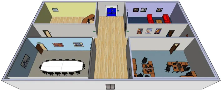
For the first pilot tests to evaluate the pilot facility, hardware and the ErgoVR system, a simple scene for simulation was created. This scene consisted in a 25 x 15 meters space, with four rooms and a cross corridor that separated them. Each room was around 9.5 x 6 meters and had a different theme associated (reception desk, meeting room, waiting room and an office). A top view of the environment can be seen in Figure 3.
There were five participants in the pilot tests and they were told to explore the environment freely between 5 to 7 minutes. During each simulation, the ErgoVR system was collecting data automatically for later analysis. The main objective of these pilot tests was to assess if the ErgoVR system was working properly in the presentation of the VE, the accuracy of the data collection and proper interaction with the VR devices. As such, after the simulation, each participant was asked for commentaries, suggestions and for difficulties encountered during the simulation. With the outputs from the ErgoVR system and the results from informal interviews with the participants, the same group of specialists had two meetings to analyze the data and propose modifications to the system for the following UCD iteration cycle. With the information generated after the meetings, changes were made to the system to correct some of the problems found by the participants and by the group of specialists.
Some examples of the required changes are to have the possibility to control the sensitivity of the navigational interface (a joystick at this point), to have the possibility to interact with certain objects in the VE and also to have the possibility to observe the path that the participant did in a top view manner to ease the subjective analysis.
After the changes made, a new set of tests were performed, in the same conditions of the pilot tests mentioned earlier (five participants and post-simulation interviews). The difference from the previous tests was that buttons were added to the environment and it was now possible to interact with them in order to perform some actions.
At the end of each cycle of the iterative process, the implemented solutions are always considered against the requirements and the results obtained from pilot tests (which are done at the final step of each cycle of the UCD). With the considerations resulting from this step new changes and requirements to the system are generated.
2.3 Description of the ErgoVR system
ErgoVR is a software-based VR system that was created as a VR model Behavioral compliance with warnings studies and for Wayfinding studies, using a User-Centered Design (ISO, 1999) approach. Although the main focus for the development of the ErgoVR system was for these types of studies, the system was also developed with an openness of allowing other types of studies. This was done by trying to generate features in the system that would be sufficiently generic that several types of studies could benefit from the features.
The ErgoVR system is composed by two separate applications to fulfill the needs of research studies: (1) simulator; and (2) log viewer. The main purpose of the simulator is to be able to simulate a study’s scenario with its related VE and provide the necessary interactivity between the participant and the VE by using different VR equipment (e.g., Head-Mounted Display,
headphones, motion sensors, among others). The log viewer’s main purpose is to allow the researcher to analyze and export the data collected during the simulation.
Both ErgoVR applications were completely developed by the author of this document, as well as all the necessary engineering decisions made to fulfill the requirements that were previously defined.
In the next topics, the ErgoVR system will be explained, taking a perspective of a researcher that wants to start a new research project and wants to use this system as a research tool. As such, the following topics focus on the features and capabilities of the ErgoVR system and how they fulfil the requirements defined, rather than focusing on the engineering point of view of the development of the ErgoVR system.
2.3.1 Global view of the system
The use of the ErgoVR system spans throughout different decision points of a research project. This happens because the scope of the ErgoVR system is vast in a research project, i.e., from the initial decisions of the main objectives of the study to the more specific details of how and what should happen during the simulation. Some of the decisions that need to be made for a research project will change the way a researcher interacts with the ErgoVR system and in a similar manner, due to the capabilities of the system and how they are used, the ErgoVR system can affect certain decisions of a research project.
For the reason that the use of the ErgoVR system encompasses different stages of a research project, as well as that the system should be usable for researchers that do not necessarily have the technical skills to add certain behaviors programmatically, it was decided that the ErgoVR system should work based on a model of pre-defined conventions of use. Although this model might, in some sense, inhibit some control over what can be personalized (only for those without the necessary technical skills), it provides a plethora of features that can fulfill the needs of different types of research projects (with a focus on behavioral compliance with warnings and wayfinding studies).
The process of using the ErgoVR system for a research project can be divided into three main stages (see Figure 4). First the VE needs to be conceptualized and created according to the requirements of the study at hand. After that, the created VE will be passed to the Simulator for the data collection stage. The recorded files from the data collection stage are then passed to the LogViewer for the data analysis stage.
This topic will describe generically how these elements work with each other, by describing: the concepts and conventions used in the creation of VEs; the features and functionalities of the simulator and; how the researcher can analyze the collected data using the LogViewer application. In each subtopic, features and functionalities that are specific to behavioral
compliance with warnings studies or wayfinding studies are mentioned as such. Other features and functionalities presented in those topics are generic and can be applied for other types of studies.
Figure 4 – The three stages of the ErgoVR's system use
The following topics will present the ErgoVR system taking into account the perspective of a researcher wanting to use it as a tool for a new research project. As such, the topics are separated into the three moments described earlier. In each one of the moments, the description of the features and capabilities of the associated part of the system are described independently. Most of these features and capabilities were created to fulfill the requirements presented in earlier topics. However, the solutions achieved for some of the requirements span over more than one stage. This will be addressed by presenting the features that cover a certain requirement for each stage separately, being the requirement presented repeatedly in the associated stage.
2.3.2 Creation of Virtual Environments
This topic describes briefly how VEs should be created to be used in the ErgoVR system.
Virtual Reality presents VEs in real-time, creating therefore a necessity of certain attention while modeling a VE. Unlike other type of 3D modeling where a render can take several hours, in VR, a scene is presented at 60 frames per second, i.e., 60 renders per second. As a consequence, to be able to render a scene at that speed, some compromises have to be made, and usually they are in the level of detail that is possible to give to a scene, its objects and materials.
Virtual
Environment
Design
Data Collection
(Simulator)
Data Analysis
(LogViewer)
The level of detail that a VE can have can be compared with what a game environment can provide up to a certain extent. A game, like in VR, needs to render at 60 frames per second. Nonetheless, in the last years it is possible to observe that the graphic quality of games is increasing considerably fast. This is possible due to the graphics cards becoming more powerful each year, with enough power to process more detail in real-time. As such, and because of this similarity with games, the environments for VR can use the same techniques that are commonly used for games. These techniques improve the visual quality of an environment to be rendered in real-time at a low computation cost. Since it is not the main scope of this document to provide a more detailed description of these techniques neither their implementation, please refer to the book “Real-Time Rendering” (Akenine-Möller, Haines, & Hoffman, 2008) for further detail. A detailed explanation (and tutorials) of some of the game techniques (e.g., bump mapping, UVW mapping) that can be applied to VR that work with the ErgoVR system are presented in (Fernandes, 2013).
The ErgoVR simulator can open and present VEs in the DotScene format. The DotScene format is a standardized XML (eXtensible Markup Language) file format made for OGRE (Object-Oriented Graphics Rendering Engine). The DotScene format presents, hierarchically the relationships of all the objects that belong to a scene. These objects can be from normal, 3D visible objects, to other elements such as cameras, lights, materials used, animations, triggers, among others.
As such, the scene itself can be modeled in any 3d modeling software (e.g., Autodesk® 3ds max, Autodesk® Maya, Blender) providing there is an available plugin capable of exporting the scene to the aforementioned DotScene format. In the Ergonomics Laboratory, the tools that were most used are Autodesk® 3ds max 2009 for the 3D modeling and scene creation and the OgreMax v2.1.2 plugin to export to the DotScene format. Another solution used to export the scene is using the EasyOgreExporter plugin, with Autodesk® 3ds max. Although there are slight changes in the DotScene file exported by both plugins, the ErgoVR system supports both (the latest version tested of EasyOgreExporter was v1.9).
Since one of the main requirements for the ErgoVR system was that it should be usable by people from other fields (e.g., Design, Architecture), meetings were made, in the different iterations of the development, to establish conventions to be used in the creation of VEs in order to be possible for the ErgoVR simulator to interpret and present those VEs without requiring additional human intervention. These defined conventions have a small level of impact of additional work for the person that is creating the VE and at the same time allow a higher level of control of the actions that will happen during the simulation.
Most 3D modeling software provide the possibility of creating dummy objects (or empty objects), which are elements that have no visual representation, yet have the basic components of an object, i.e., they have a position and an orientation, as well as may have children objects
associated with them. As such, these elements (i.e., dummy objects) may be used to define the VE's hierarchal structure, which in turn will facilitate its automatic processing by the simulator. The base template for the creation of VEs to be used in the ErgoVR system is composed of a set of dummy objects with the following pre-defined names: 1) Static; 2) Movable; 3) Boxed; 4) NoPhysics; 5) ObservableObjects; and 6) Events. The Events object has two direct children: 6.1) Triggers; and 6.2) Actions.
This template will force the VE modeler to create a structured approach when creating the VE (which most likely already had) allowing at the same time to focus on the interaction outcome of the VE, without the intervention of more specialized elements of the team. The first four items of the template are related with the physics of the VE. Any object that is a children of the dummy object Static, will be considered as a static, fixed physical element that cannot be crossed over or moved. If there are elements that are intended to move and have natural physical reactions to collisions, they should be placed as children of the Movable dummy object. For more complex objects (i.e., complex forms that are not basic primitives) and where the type of interaction that is intended with them is low (i.e., only to check if there’s a collision), it is advisable to place those objects as children of the Boxed dummy object. This will have two effects: 1) An invisible physical box will be placed that contains the object inside; and 2) since it is a simpler physics object, it will ease the necessary calculation work on the Physics system, which will improve performance of the simulation. Following the same reasoning, there might be some objects that the participants will not be able to interact. As such, those objects should be under the NoPhysics dummy object, which will tell the simulator to not generate physical elements for those objects. The dummy object ObservableObjects is for objects that are intended to know if participants of the study looked at (i.e., the center of the screen, until an eye-tracker system is integrated into the simulator).
The Events dummy object and its direct children objects Triggers and Actions are where objects related with the events in the VE should be placed. 3D modeling software usually allows to add extra textual information to an object. Using that feature of the software, the Events dummy object is where the VE modeler should place the information that defines the association between the triggers and actions. More details regarding this subject are presented in the description of the Event System in topic 2.3.3 - Simulator. The events and respective actions need to be defined, and therefore need to be fully considered, at the design time of the VE to fulfill the specific study’s objectives, i.e., when the scenario with the context is being defined. By defining the events and actions at the design time, the VE modeler is encouraged to follow the best practices of testing early and often.
The initial position in the VE of the participant is also an important aspect and how that could be achieved in an easy manner by the VE modeler. As such, it was defined that creating a Camera
with the name “StartPosition” would determine that initial position. The rotation and the point where the camera was looking at are also adopted automatically by the ErgoVR system.
Another important aspect of the creation of VEs is the necessity, for certain studies, to have virtual humans present in the VE. As such, certain considerations should be taken into account while developing virtual humans to use in VEs for the ErgoVR system. The simulation of virtual humans is an immense challenge requiring solving many problems in various areas (Magnenat-Thalmann & (Magnenat-Thalmann, 2004). Some of the challenges pass through: having a good representation of faces and bodies; having a flexible motion control to reproduce motion naturally; for autonomous virtual humans it is required to be able to reproduce a high-level type of behavior that is plausible and believable; the virtual humans should be able to have and present emotional behavior; having a realistic appearance in terms of hair, skin and clothes; being able to interact with the VE in a natural way (i.e., by interacting with other virtual objects or by having social exchanges with other virtual humans); and being aware of the presence of the actions of the participant and acting accordingly (e.g., deviating from the participant, looking at the participant if looked at).
At this moment, the support for virtual humans in the ErgoVR system is limited in a way that only allows to have virtual humans with pre-defined behaviors which are represented by animations (body and face) and the use of sounds (e.g., to represent someone speaking). There are several 3D human modeling software available (e.g., Smith-Micro Poser5, DAZ Studio6, MakeHuman7) that allow to create a virtual human, where it is possible to change different features of a person (e.g., age, gender, race, height, weight) and also create body and facial animations. Depending of the software used, facial animations can also be associated with speech sounds.
Also regarding the 3D human modeling software, it is possible to export the virtual human as a low-polygon mesh and already rigged for animation to be imported in 3D modeling software, which is appropriate to use in settings where it is required rendering at high rates, such as in VR. As such, the process to create virtual humans to be included in VEs goes by using one of the available 3D human modeling software and define there the intended characteristics of the virtual human (e.g., gender, height, clothes). After that, the animations necessary for the study at hand should be defined, including facial animations for speech simulation if required. After that, the virtual human should be exported to be included in the VE. For that, a low-polygon mesh should be used and it should also include the rigged animation skeleton. In the 3D modeling software, the virtual human should be imported and placed inside the VE in the desired location. It is in this moment of the process that the modeler should pay attention if the animations were
imported correctly and also the modeler needs to associate each animation with a speech sound and the moments when they would play in the VE. This should be done in the format expected by the Event System, described in more detail in next topic (2.3.3 - Simulator). For more details, with a full tutorial on how to create virtual humans to be used in the ErgoVR system, please see (Vital, 2012).
Even though the creation of VEs was only briefly summarized in this topic, since it is not the core focus of this research work, it is clear that it is a discipline that requires detailed knowledge of several different fields, which can only be possible in a multidisciplinary team with members that have the needed expertise. It is also a task that requires extreme detailed planning and time for its development.
2.3.3 Simulator
In this topic it is described the Simulator component of the ErgoVR system. The focus presented is in terms of the features and functionality of the simulator and how they connect to the requirements presented earlier in topic 2.2.2 - Requirements. First it will be presented a global view of the system and a brief description of the modules that compose the ErgoVR simulator. Next, the custom built modules are described in detail. The topic finishes with an overview of the currently compatible hardware that can be used with the ErgoVR system.
a) Global view of the simulator
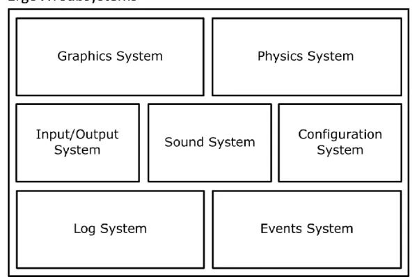
The ErgoVR simulator is made by several subsystems as it can be seen in Figure 5. Some of the systems are composed mostly by free and open-source code libraries with a small amount of custom code. The exceptions are the Configuration, Log, Events systems and the main ErgoVR application which were custom developed in its entirety and resulted in the final simulator. The ErgoVR system was developed over the Microsoft® .NET Framework using C++/CLI and C# (C sharp) programming languages. At this moment, the ErgoVR only works on computers with Microsoft® Windows installed. This decision was made because of the nature of the software being developed, which has similar requirements as a video game, and because Microsoft® Windows is the only operating system with better support for the underlining graphics systems that is mostly used for games (DirectX). In the beginning of the development of the ErgoVR system, DirectX was much more advanced than the OpenGL counterpart (also used in Windows, but mostly used in Linux and Mac), which would limit the type of visual information that could be placed in the Virtual Environments that would be developed for the studies. Also, the support from the VR equipment used was mostly Windows-centric which also weigh in the decision. Despite these reasons, there are plans to make the ErgoVR work with the Mono8 project (which
is an open-source implementation of the .NET Framework) in the future, which would also work in Linux and Mac computers.
Figure 5 - Diagram with the subsystems that compose the ErgoVR simulator
The subsystems are: (1) graphics engine; (2) physics engine; (3) sound engine; (4) input/output system; (5) configuration system; (6) log system; and (7) events system.
1. The graphics engine is responsible for presenting the VE to the participant. This system loads and keeps tracks of all the elements of the VE so it can transmit the resulting image (i.e., render) to the Input/Output system to be presented in the output device that is being used at the moment. At the moment, it uses the Object-Oriented Graphics Rendering Engine (OGRE9) v1.7.3 library in its core. The OGRE library is a full-featured graphics engine which can present different types of visual effects and it is also able to load complex scenes with low processing requirements;
2. The physics engine is responsible for the detection of collisions with objects and introduces physical behavior to the objects within the VE (e.g. if the user collides with a ball inside the VE, the ball will roll with the appropriate speed depending on the force applied in the collision). At the moment, this system is the Newton Game Dynamics10 v1.35 physics engine which is able to represent physical interactions between objects with a high level of control and realism;