Universidade de Brasília
Instituto de Ciências Exatas Departamento de Ciência da Computação
Autonomic Goal-Driven Deployment in Heterogeneous
Computing Environments
Gabriel Siqueira Rodrigues
Dissertação apresentada como requisito parcial para conclusão do Mestrado em Informática
Orientadora
Prof.a Dr.a Genaina Nunes Rodrigues
Brasília
2016
Universidade de Brasília — UnB Instituto de Ciências Exatas
Departamento de Ciência da Computação Mestrado em Informática
Coordenadora: Prof.a Dr.a Célia Ghedini Ralha
Banca examinadora composta por:
Prof.a Dr.a Genaina Nunes Rodrigues (Orientadora) — CIC/UnB
Prof. Dr. Vander Ramos Alves — CIC/UnB Prof. Dr. Raian Ali — Bournemouth University
CIP — Catalogação Internacional na Publicação Rodrigues, Gabriel Siqueira.
Autonomic Goal-Driven Deployment in Heterogeneous Computing En-vironments / Gabriel Siqueira Rodrigues. Brasília : UnB, 2016.
103 p. : il. ; 29,5 cm.
Dissertação (Mestrado) — Universidade de Brasília, Brasília, 2016. 1. Engenharia de requisitos, 2. Variabilidade Arquitetural,
3. Ambientes Heterogêneos, 4. Implantação Automatizada CDU 004.4
Endereço: Universidade de Brasília
Campus Universitário Darcy Ribeiro — Asa Norte CEP 70910-900
Universidade de Brasília
Instituto de Ciências Exatas Departamento de Ciência da Computação
Autonomic Goal-Driven Deployment in Heterogeneous
Computing Environments
Gabriel Siqueira Rodrigues
Dissertação apresentada como requisito parcial para conclusão do Mestrado em Informática
Prof.a Dr.a Genaina Nunes Rodrigues (Orientadora) CIC/UnB
Prof. Dr. Vander Ramos Alves Prof. Dr. Raian Ali CIC/UnB Bournemouth University
Prof.a Dr.a Célia Ghedini Ralha
Coordenadora do Mestrado em Informática
Agradecimentos
Firstly, I would like to express my gratitude to my advisor, Genaína, for her enthusi-asm, patience and wisdom. Which was fundamental to the conclusion of this work. And to the members of our research group Danilo Mendonça and Felipe Pontes.
Resumo
Vemos um crescente interesse em aplicações que devem contar com ambientes de com-putação heterogêneos, como a Internet das Coisas (IoT). Esses aplicativos são destinados a executar em uma ampla gama de dispositivos com diferentes recursos computacionais disponíveis. Para lidar com algum tipo de heterogeneidade, como dois tipos possíveis de processadores gráficos em um computador pessoal, podemos usar abordagens simples como um script que escolhe a biblioteca de software certa a ser copiada para uma pasta. Essas abordagens simples são centralizadas e criadas em tempo de design. Eles re-querem um especialista ou equipe para controlar todo o espaço de variabilidade. Dessa forma, essas abordagens não são escaláveis para ambientes altamente heterogêneos. Em ambientes altamente heterogêneos, é difícil prever o ambiente computacional em tempo de projeto, implicando provavelmente indecidibilidade na configuração correta para cada ambiente. Em nosso trabalho, propomos GoalD: um método que permite a implantação autônoma de sistemas, refletindo sobre os objetivos do sistema e seu ambiente computa-cional. Por implantação autônoma, queremos dizer que o sistema é capaz de encontrar o conjunto correto de componentes para o ambiente computacional alvo, sem intervenção humana.
Nós avaliamos nossa abordagem em um estudo de caso: conselheiro de estação de abastecimento, onde uma aplicação aconselha um motorista onde reabastecer / recarre-gar seu veículo. Nós projetamos a aplicação com variabilidade em nível de requisitos, arquitetura e implantação, o que pode permitir que a aplicação projetada seja executada em diferentes dispositivos. Para cenários com diferentes ambientes, foi possível planejar a implantação de forma autônoma. Além disso, a escalabilidade do algoritmo que planeja a implantação foi avaliada em um ambiente simulado. Os resultados mostram que usando a abordagem é possível planejar de forma autônoma a implantação de um sistema com milhares de componentes em poucos segundos.
Palavras-chave: Engenharia de requisitos, Variabilidade Arquitetural, Ambientes Hete-rogêneos, Implantação Automatizada
Abstract
We see a growing interest in computing applications that should rely on heterogeneous computing environments, like Internet of Things (IoT). Such applications are intended to execute in a broad range of devices with different available computing resources. In order to handle some kind of heterogeneity, such as two possible types of graphical processors in a desktop computer, we can use simple approaches as a script at deployment-time that chooses the right software library to be copied to a folder. These simple approaches are centralized and created at design-time. They require one specialist or team to control the entire space of variability. However, such approaches are not scalable to highly het-erogeneous environments. In highly dynamic and hethet-erogeneous environment it is hard to predict the computing environment at design-time, implying likely undecidability on the correct configuration for each environment at design-time. In our work, we propose GoalD: a method that allows autonomous deployment of systems by reflecting about the goals of the system and its computing environment. By autonomous deployment, we mean that the system can find the correct set of components, for the target computing environment, without human intervention.
We evaluate our approach on the filling station advisor case study where an application advises a driver where to refuel/recharge its vehicle. We design the application with variability at requirements, architecture, and deployment, which can allow the designed application be executed in different devices. For scenarios with different environments, it was possible to plan the deployment autonomously. Additionally, the scalability of the algorithm that plan the deployment was evaluated in a simulated environment. Results show that using the approach it is possible to autonomously plan the deployment of a system with thousands of components in few seconds.
Keywords: Requirements Engineering, Architecture Variability, Heterogeneous Environ-ments, Automated Deployment
Contents
1 Introduction 1 1.1 Problem Definition . . . 1 1.2 Proposed Solution . . . 3 1.3 Contributions Summary . . . 3 1.4 Structure . . . 4 2 Background 5 2.1 Context-aware Systems . . . 5 2.2 Self-Adaptive Systems . . . 62.2.1 Development of Self-Adaptive Systems . . . 7
2.3 Goal Modeling . . . 8
2.3.1 Software Deployment . . . 9
2.4 Software Components . . . 10
2.4.1 Component-Based Adaptation . . . 11
2.4.2 From Goals to Components . . . 12
3 Filling Station Advisor 14 3.1 Motivating Example: The Filling Station Advisor . . . 14
4 The GoalD Approach 17 4.1 Offline . . . 18
4.1.1 Goal Modelling . . . 18
4.1.2 From Goals to Components Specification . . . 19
4.1.3 Packaging Components into Artifacts . . . 21
4.1.4 Development Process . . . 24
4.1.5 Activities . . . 24
4.2 Online . . . 25
4.2.1 Automated Deployment Planning . . . 26
4.2.2 Deployment Execution . . . 28 5 Evaluation 31 5.1 Feasibility Assessment . . . 32 5.2 Scalability Assessment . . . 34 5.3 Threats to validity . . . 35 6 Related Work 37
7 Conclusion 39 7.1 Conclusion and future work . . . 39
List of Figures
2.1 Context-aware services framework by [24] . . . 5
2.2 MAPE-K Reference Architecture . . . 6
2.3 A Life-cycle model for Self-Adaptive Software System[3] . . . 7
2.4 Artifacts Deployment . . . 10
3.1 CGM of the filling station advisor . . . 15
3.2 Variability in the Computing Environment . . . 16
4.1 Overview of the steps in GoalD . . . 17
4.2 Artifact Structure . . . 22
4.3 Dependency graph . . . 23
4.4 Roles collaboration . . . 24
4.5 Deployment Process Activities . . . 25
4.6 Goald Autonomic Deployment . . . 26
4.7 The GoalD Deployment metamodel . . . 27
4.8 Representation of OSGi bundles lifecycle . . . 30
5.1 Computing Environment Evaluation Scenarios . . . 33
5.2 Passing Tests . . . 33
5.3 Scalability over the size of plan . . . 34
Chapter 1
Introduction
Nowadays, people are surrounded by different devices with computing capability. Phones, watches, TVs, and cars are example of daily devices for which there are smart versions with computing capability and where is possible to install software applications. Typically, these devices have connectivity capability and can form networks. These net-works can be rich computing environments as each device brings different computing resources. This presents a great potential, but developing software that harvests the ca-pability of such environment is challenging. In this work, we call such an environment a highly heterogeneous computing environment as it is formed by different sets of devices, with different resources, and which are only partially known at design-time. Ubiquitous Computing [11], Internet of Things (IoT) [8], Assisted Living [34] and Opportunistic Com-puting [53] are examples of comCom-puting architectures that have to be typically designed for a highly heterogeneous computing environment.
Software deployment is the process of getting a software ready to be used in a given computing environment[16]. It involves planning which artifacts should be deployed, moving compatible artifacts to the target environment, configuring the environment and starting execution. Deployment planning is a specially challenging activity, it requires analyzing the environment and the software architecture to solve variabilities, and coming up with which software artifacts should be present in the deployment.
1.1
Problem Definition
Current software deployment approaches do not suit highly heterogeneous computing environment[42]. The simplest approach to deployment as a whole is manual configura-tion, in which a human conducts all steps in the deployment planning and execution. It is normally applied when developing customized software that will be executed in devices managed by the development team. Such approach does not scale for applications that target massive use, because it requires the deployment to be executed by a person with knowledge about the application internals[4]. Another approach, common in cloud en-vironments, is the use of scripts to automate software deployment execution[54]. Such approach is normally used in virtualized environments that simulate a very homogeneous environment. The scripts are tailored at design-time a specific target environment. When some variability can be solved at deployment-time with conditionals in the script, it does not scale as the script relies on a centralized model created at design-time. Software
store is another alternative approach. Typically, the developer uploads to the store back-end site the software configuration for each kind of target device, solving any variability at this point. In such cases, the deployment execution can rely on actions by the end-user such as accessing the store interface, searching for the application, and initiating the installation of the application. Neither scripts nor software stores are suitable for heterogeneous environments because they are highly dependent on a centralized method for deployment that requires knowledge about the target environment at design-time. In summary, current approaches for deployment do not suit deployment in highly heteroge-neous computing environments as they require human interaction or knowledge about the runtime environment at design-time.
The challenges related to deployment in emerging highly heterogeneous computing environment can be summarized as follows:
• Challenge 1: heterogeneity. The system is meant to run in a broad range of configurations of the computing environment.
• Challenge 2: uncertainty at design-time. The system architec/developer cannot precisely ascertain the configuration of the end user computing environment. • Challenge 3: deployment should be autonomous. A deployment special-ist is unlikely available at deployment time for a particular environment, so the deployment should be planned and executed autonomously.
Many works have investigated the relation of goals and architecture of a system [35][46][47][48][60]. Some works in the literature have investigated variability in goal mod-els with adaptation purpose [5][63]. These works show that goal modeling is a promising approach to manage variability at the design of the software. But, to the best of our knowledge, none investigated goal models at deployment level. Accordingly, our first research question emerges:
Research Question 1 (RQ1): Would a goal-driven approach be suitable to manage variability at deployment?
With RQ1 we are interested in extending goal-oriented variability models to deploy-ment level. By addressing RQ1, we expect to allow the deploydeploy-ment of the system to be adaptable to the characteristics of the target environment. However, in order to allow the adaptation, we also need to solve the variability, that is, we need to evaluate the points of variability of the system and the characteristics of the environment, and come up with a valid configuration that adapts the system deployment for the environment. From this, our second research question arises:
Research Question 2 (RQ2): Is it feasible and scalable to solve deployment vari-ability autonomously at deployment time?
With RQ2, we will investigate how to autonomously solve the variability, then finding a deployment plan that allows the achievement of user goals in the target computing environment.
1.2
Proposed Solution
This work proposes GoalD: a method that follows a goal-oriented approach for deploy-ment in highly heterogeneous computing environdeploy-ments, capable of determining a suitable configuration from a general set of configurations for deployment. In particular, we focus on autonomous deployment planning as the major part of the deployment in heteroge-neous environments. In our approach, the planning is executed autonomously, that is, it does not require a human to interact with the system at deployment time.
An abstract model is used that consider the following information: (i) what the system needs to achieve (i.e., the goals), (ii) how it can achieve the goals (i.e., its alternative strategies), and (iii) the restrictions to the strategies (i.e., the resources needed). Part (i) comprehends requirements modeling. Part (ii) comprehends artifacts containing software components and metadata. Part (iii) comprehends conditions that can be evaluated against the environment in order to find if a given artifact can be deployed.
Goal-oriented Requirements Engineering is a suitable modeling approach to model what the user wants to achieve, where system requirements are modeled as intentions of actors in strategic goals[15][21][62]. Context goal models (CGMs) extend goal models[1], inserting the context as another dimension. We propose to use CGMs to model resource as context information that restricts how goals can be achieved, or more specifically which artifacts can be deployed.
GoalD consists of: (i) rules to refine context-goal models into software components; (ii) a description on how to create artifacts as packaged components with deployment metadata information; (iii) a deployment metamodel that characterize deployment infor-mation; (iv) an algorithm to analyze the deployment metamodel and, for a given comput-ing environment together with a set of goals, select an appropriate set of artifacts that allows the achievement of the goals in the computing environment. GoalD was evaluated in a case study and using a randomly generated workload. The results show that the approach can be used to guide the development and the autonomous planning is able to plan the deployment of a system with thousands of artifacts in seconds.
1.3
Contributions Summary
This section summarizes the major contributions of this proposal.
1. A method to develop systems for heterogeneous computing environments that sup-ports variability for software deployment, comprising:
• patterns to map components from a contextual goal model (CGM)
• guide on how to package the components into artifacts keeping variability 2. An approach to autonomously plan the deployment at the target environment
com-prising:
• A metamodel that describes the deployment
• An algorithm to autonomously planning the deployment • A Java implementation of the algorithm
1.4
Structure
This dissertation is organized as follows. Chapter 2 introduces the theoretical back-ground underlying our work. Chapter 3 Presents the case study of the Filling Station Advisor. Chapter 4 presents patterns and guidelines to develop software to heterogeneous computing environments and the support for autonomous deployment. Chapter 5 depicts the evaluation of GoalD. Chapter 6 presents most relevant related literature work and Chapter 7 concludes and outlines future works.
Chapter 2
Background
This chapter briefly reviews the concepts used throughout this work.
2.1
Context-aware Systems
Context-aware systems are those able to adapt their behavior according to changing circumstances without user intervention. Finkelstein and Savigni [24] describe a frame-work for context-aware services. Their approach is depicted in Figure 2.1.
Figure 2.1: Context-aware services framework by [24]
Environment is whatever in the world provides a surrounding in which the agent is supposed to operate. The environment comprises such things as characteristics of the device that the agent is expected to operate in. Context is the reification of the environ-ment. The context provides a manageable, easily computer manipulable description of the environment. A context-aware system should watch relevant environment properties and keep a runtime model that represents those properties. By reasoning about that model the system can change its behavior. A context can be either an activator of goals or a precondition on the applicability of a certain strategy to reach a goal.
A goal is an objective the system should achieve. It is an abstract and long-term objective of the system. A requirement operationalises a goal. It represents a more
concrete and short-term objective that is directly achievable through actions performed by one or more agents. Service description is the meta-level representation of the actual, real-world service. It should be a suitable formalism that allows services to be compared to requirements in order to identify runtime violations. Service provides the actual behavior as perceived by the user.
A reflective system is a system which incorporates structures representing (aspects of) itself. A causal connection between a model and a modeled element exists if one of them changes, this leads to a corresponding effect upon the other [38]. Following this approach, the system should keep a causal connection between the service and the description. The system adapts by manipulating the service description. Following the requirements reflection vision [13], a system should keep software requirements model at runtime, and use such model to drive the system adaptation.
2.2
Self-Adaptive Systems
Self-adaptivesses is an approach in which the system "evaluates its own behavior and changes behavior when the evaluation indicates that it is not accomplishing what the soft-ware is intended to do, or when better functionality or performance is possible."[36]. Self-adaptive systems (SAS) aims to adjust various artifacts or attributes in response to changes in the self and in the context of a software system[51].
A key concept in self-adaptive systems is the awareness of the system. It has two aspects[51]:
• context-awareness means that the system is aware of its context.
• self-awareness means a system is aware of its own states and behaviors.
Schilit et al.[33] define context adaptation as “a system’s capability of gathering in-formation about the domain it shares an interface with, evaluating this inin-formation and changing its observable behavior according to the current situation”.
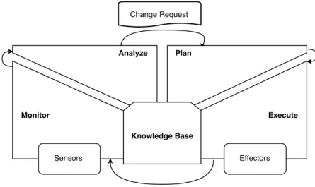
Figure 2.2: MAPE-K Reference Architecture
MAPE-K is a reference architecture originally proposed for autonomic computing [32] and that is often used as a model for architectures of SAS. It has a control loop, realized by
a simple sequence of four activities: monitor, analyze, plan, execute and a knowledge are. The adaptive system interacts with the environment or managed sub-system through sensors and actuators. The monitor activity collects data from sensors. That data is analyzed, and if a need of change is identified, a change request is dispatched, them an adaptation should be planned. The resulting plan is passed to the execute activity, which is performed through actuators.
2.2.1
Development of Self-Adaptive Systems
For SAS some activities that traditionally occur at development-time are moved to runtime. Andersson et al. [3] proposed a process for development of adaptive systems. In their approach, activities performed externally to the adaptive system are referred as off-line activities, and activities performed internally in the adaptive system are on-line activities. Off-line activities are mainly related to the design of the system, while online activities are related to the run-time of the system.
Figure 2.3: A Life-cycle model for Self-Adaptive Software System[3]
The left-hand side of Figure 2.3 represents a development life-cycle model. Off-line activities work on design model and source code in a product repository and produce the artifacts that will be used in the running system. The right-hand side of Figure 2.3 depicts a running SAS. In this approach, we have Domain Logic that is responsible for final user goals achievements. Adaptation Logic is responsible for adapting the system in response to changes in the environment. In addition, the adaptation logic implements a control loop in line with the monitor-analyze-plan-execute (MAPE) loop [32].
2.3
Goal Modeling
Goal-Oriented Analysis is a requirements engineering approach that captures and doc-uments the intentionality behind requirements. Goal-Oriented Requirements Engineering (GORE) approaches have gained special attention as a technique to specify adaptable systems [45]. Goals capture the various objectives the system under consideration should achieve. In particular, Tropos[15] is a methodology for developing multi-agent systems that uses goal models for requirement analysis.
The Tropos key concepts
Tropos uses a modeling framework based on i* [62] which proposes the concepts of actor, goal, plan, resource and social dependency to model both the system-to-be and its organizational operating environment [15] [44].
In Tropos, requirements are represented as actors goals that are successively refined by AND/OR refinements. There are usually different ways to achieve a goal, and this is captured in goal models through multiple OR refinements.
Key concepts in the Tropos metamodel are:
Actor is an entity that has strategic goals and intentionality Agent is the physical manifestation of an actor.
Goals represent actors’ strategic interests. Hard goals are goals that have clear-cut crite-ria for deciding whether they are satisfied or not. Soft goals have no clear-cut critecrite-ria and are usually used to describe preferences and quality-of-service demands. Plans represent a way of doing something. Plans are concrete actions or procedures that
an agent can perform. The execution of a plan can be a means for satisfying a goal or for satisficing (i.e. sufficiently satisfying) a soft goal.
Resource represents a physical or an informational entity.
Dependency it is a relationship between two actors that specify that one actor (the depended ) has a dependency to another actor (the dependee) to attain some goal, execute some plan or deliver a resource. The object of the dependence is the depen-dum.
Capability represents both the ability of an actor to perform some action and the op-portunity of doing so.
In Tropos requirements are represented as actors goals that are successively refined by AND/OR refinements. There are usually different ways to achieve a goal, and this is captured in goal models through multiple OR refinements.
Goal models are a traditional requirements tool, as such it must capture the solution space and are not sufficiently detailed to reason about system execution and do not capture information on the status of requirements as the system is executing, nor on the history of an execution [14]. Traditional goal models can be named design-time goal model (DGM). Dalpiaz et al.[20] describe a method for extending Design-time Goal Models (DGMs) to
create Runtime Goal Models (RGM). RGMs can be used to analyze the system’s runtime behavior. Other works relate goal models with another dynamic aspects of systems, such as configuration [63], behavior [20], probability of achieving success [41] and achievability of goals [49].
Salehie et al. [52] propose a run-time goal model and its related action selection. They model adaptable software as a system that exposes sensors and effectors and proposes a model consisting in Goals, Attributes, and Action for selecting actions that will affect the adaptable software at runtime, giving sensed attributes. So the adaptation mechanism is to choose the best action given the actual attributes. It uses explicit runtime goals and makes them visible and traceable.
Contextual Goal Model
Contextual Goal Model, proposed in [1], captures the relation between system goals and the changes into the environment that surround it. Context goal models extends goal models with context information. Goals and context is related by inserting context conditions on variation points of the goal model. Context Analysis is a technique that allows to derive a formula in verifiable peaces of information (facts). Facts are directed verified by the system, while a formula represents whether a context holds.
Mendonça et al. [41] propose GODA: a methodology for dependability analysis by which the software engineer, at design-time, annotates the goal decomposition in goal model and specify context variables. A special tool generates a formula to evaluate for a given context the probability of achieving a goal at runtime.
2.3.1
Software Deployment
Software deployment refers to all activities that make a software system available for use[16]. These activities result in the creation and distribution of artifacts, from the devel-opment environment to the target runtime environment. Artifacts are files that package software components and assets. The deployment process can vary depending on the application domain and execution platform. In embedded platforms, the deployment can consist in burning software into a chip. In consumers’ personal or business domain, for a desktop platform, the deployment can consist of an installation process with collaboration between a person and a script that automates some steps. In an enterprise domain, for a web platform it can consist in coping and editing some files in a couple of machines. In many of those scenarios software will be periodically updated, frequently becoming unavailable during the update process. The complexity of the software deployment can also vary as a function of how much the platform is distributed (i.e. the number of nodes), how much heterogeneous it is, and how much is known about the deployment computing environment at design-time. In a dynamic and heterogeneous environment deployment can be specially complex.
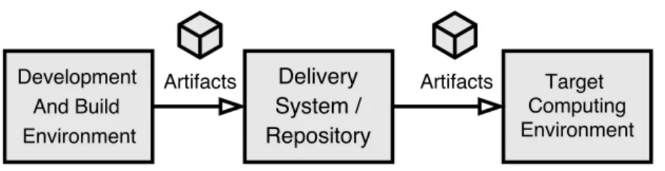
Deployment artifacts are the artifacts needed at the deployment environment. Ar-tifacts are built at development and build environment. Built arAr-tifacts are moved to a delivery system where they can be accessed from the target environment. At deployment the artifacts are moved from the delivery system to the target computing environment. Also, configuration activities can be realized. In the software industry, a continuous in-tegration[30] environment applies automation in building and getting components ready
Figure 2.4: Artifacts Deployment
to delivery. In such environment if a developer pushes changes to a code repository, components are automatically built and published to delivery system. The build process commonly involves fetching build dependencies, compiling source code, running auto-mated quality control (tests and static analysis) and packaging components into artifacts. Artifacts are published if target quality policies are met. Fundamental to continuous in-tegration environments are Dependency Management Systems tools, such as Maven[7] for Java platform. These tools simplify the management of software dependencies [55]. Such tools ensure that development team members are working with same dependencies that are used in the build environment.
Research in software configuration and deployment, has focused on responding to dy-namisms in a known environment. This could be costs and failures in a cloud environmet [23], changes in managed resources [27], and changes in the context of operation [12].
Continuous delivery[30] extends the continuous integration environment, moving com-ponents from the delivery system to a target computing environment with none or mini-mum human intervention.
In the industry, package managers such as aptitute/apt-get(Debian based Linux distri-butions) [6], yum (Red Hat based Linux distridistri-butions) [56], Homebrew (MacOS)[29] and Chocolatey (Windows)[17] are capable of solving dependencies and deploying software. They require that a managed application declare their dependencies by name and version. DevOps[9] is a movement in software industry that advocates that all configuration steps needed to configure the computing environment should be written as code (infrastructure as code), following best practices of software development. That movement favors the doc-umentation, reproducibility, automation and scalability. DevOps allows for management of scalable computing environments. It can offer a significant advantage for enterprise en-vironment in relation to manual approaches in which system administrators configure the system by manually following configuration steps. Current continuous integration/deliv-ery and DevOps practices are not sufficient for highly dynamic and heterogeneous target computing environments; they require that highly specialized system administrators to analyze the environment and create environment configuration descriptors.
2.4
Software Components
Heineman defines software component as a “software element that conforms to a com-ponent model and can be independently deployed and composed without modification according to a composition standard”[28].
Software components are units of composition. Software systems are built by compos-ing different components. Software components must conform to a component model by having contractually specified interfaces and explicit context dependencies only.[58].
A component interface “defines a set of component functional properties, that is, a set of actions understood by both the interface provider (the component) and user (other components, or other software that interacts with the provider)”[19]. A component in-terface has a role as a component specification and also a means for interaction between the component and its environment. A component model is a set of standards for a component implementation. These standards can standardize naming, interoperability, customization, composition, evolution and deployment.[28] The component deployment is the process that enables component integration into the system. A deployed compo-nent is registered in the system and ready to provide services[19]. Compocompo-nent binding is the process that connects different components through their interfaces and interaction channels.
Software architecture deals with the definition of components, their external behavior, and how they interact[31]. The architectural view of a software can be formalized via an architecture description language (ADL)[40].
Component-based software engineering (CBSE) approach consists of building systems from components as reusable units and keeping component development separate from system development[19].
CBSE is built on the following four principles[19]:
• Reusability. Components, developed once, have the potential for reuse many times in different applications.
• Substitutability. Systems maintain correctness even when one component replaces another.
• Extensibility. Extensibility aims to support evolution by adding new components or evolving existing ones to extend the system’s functionality.
• Composability. A system should support the composition of functional properties (component binding). Composition of extra functional properties, for example, com-position of components’ reliability, is another possible form of comcom-position.
2.4.1
Component-Based Adaptation
In the literature, there has been proposals of framework for architecture and compo-nents based adaptation.
Rainbow[26] is a framework for architecture based self-adaptation. It keeps a model of the architecture of the system and can be extended with rules to analyze the system behavior at runtime, find adaptation strategies and perform changes. It separates the functional code (internal mechanisms) from adaptation code (external mechanism) in a schema called external control, influenced by control theory.
MUSIC[50] project provides a component-based middleware for adaptation that pro-poses to separate the self-adaptation from business logic and delegate adaptation logic to generic middleware. It adapts by evaluating in runtime the utility of alternatives, to chose a feasible one (e.g., the one evaluated as with highest utility).
Flashmob [57] is an approach for distributed self-assembly. Different from MUSIC and Rainbow, it handles component-based adaptation in a distributed environment. The self-assembly can be described as: given a set of available components (with various functional and non-functional properties), and a configuration of components which are already running, find a new configuration which works (better) in the changed execution environment (including hardware), meets new user requirements or takes account of new component implementations [57]. Flashmod uses a three-layer model: goals, management and components proposed by Kramer and Magee [35], extending it to allow distributed agreement in a given configuration.
OSGi[59] is a Java centric platform that allows dynamic bind and unbind of compo-nents, usually named bundles. Ferreira et al.[22] proposed a framework for adaptation based on OSGi.
2.4.2
From Goals to Components
Lamsweerde [60] presents a method for deriving architecture from KAOS goal model[21]. Firstly, an abstract draft is generated from functional goals. Secondly, the architecture is refined to meet non-functional requirements such as cohesion.
Pimentel et al. [48] present a method using i* models to produce architectural models in Acme, a language employed to describe architectural models. Firstly, i* model is transformed into a modular i* model employing a horizontal transformation. Secondly, an architecture model is created from the i* modularized model employing a vertical transformation. Architectural design models is made easier by the presence of actor and dependency concepts.
Yu et al. [63] proposed an approach for keeping the variability that exists in the goal model into the architecture. It presents a method for creating a component-connector view from a goal model. A preliminary component-connector view is generated from a goal model by creating an interface type for each goal. The interface name is directly derived from the goal name. Goals refinements result in the implementation of components. If a goal is And-decomposed, the component has as many requires interfaces as subgoals.
C o m p o n e n t G { p r o v i d e s IG ;
r e q u i r e s IG1 , IG2 ; }
If the goal is OR-decomposed, the interface type of subgoals are the interface type of the parent goal.
C o m p o n e n t G1 { p r o v i d e s IG ; } C o m p o n e n t G2 { p r o v i d e s IG ; }
Dependency Injection
Dependency Injection is a pattern that allows for wiring together software components that were developed without the knowledge about each other. [25]
In OO languages normally one instantiates an object from a class using an operator (new for Java) and a reference to such class. Interfaces create architecture independence. Yet, even using interfaces we can can have static dependencies at some point, at the implementation instantiation. The object that is instantiating (the client) is dependent on the referenced class (the service).
So the use of the new operator lead to the following disadvantages: • impose compile time dependency between two classes
• impose runtime dependency between two classes
In case of strongly typed languages, normally one will get an exception if the referenced class is not present.
The basic idea of the Dependency Injection is to have a separate object, an assembler, that wires together the components at runtime[25]. The client class refers to the service using its interface (the service interface). The assembler can use alternative ways to the new to instantiate an object so that the wiring between client objects and implementation service classes could be postponed to runtime. Using reflexive platforms we can eliminate the static dependency as the platform can find available interfaces implementations at runtime. The assembler can use reflexive capabilities of the platform to discover the available implementations and instantiate them.
In the context of component-based adaptation, decoupling client components from service components would be specially useful, allowing runtime reasoning about what implementation to choose.
Chapter 3
Filling Station Advisor
3.1
Motivating Example: The Filling Station Advisor
In this work, we use a filling station advisor application as a case study to exemplify the application of our approach. Filling station here refers to a place where the car can be refueled or recharged (gas station/petrol or charge station). The main goal of the filling station advisor is to give directions to a driver about nearby filling stations that can be reached conveniently. By convenient we mean that certain conditions for the chosen station have to be fulfilled as well as user preferences are considered. Examples of conditions are: fuel is compatible with the vehicle; station is located inside the vehicle distance-to-empty. Examples of users preferences are: low price, low number of stops, small deviation from an actual route, and station reputation.
In this work, we will focus on the challenge of handling the computing variability when developing such application. To maximize the utility, the filling station advisor should be able to run in a broad range of devices like smart-phones and car navigation systems. Each of such devices can have a different set of resources that can be used to find a convenient filling station according to the user preferences. For example, in a scenario (s1) where a human driver is using the application with a smart phone, we could use the GPS resource to track the position and the distance since the last refueling; the Internet connection to find nearby filling stations; the device text-to-speech engine to create a voice message to alert the driver when he is passing by a convenient filling station. In another scenario (s2), in which the application is running in onboard computer of an Internet connected self-driving car, we could use a more precise distance-to-empty data from onboard computer, and replace the text-to-speech notification with a system call to the vehicle self-driving system advising the next filling station stop.
The main goal of the application is refined in the following five goals, each one with its own computing resources requirements:
Get Position: the system should identify the vehicle position using an available posi-tioning system. To fulfil such goal, a GPS or cell antenna triangulation could be used.
Assess Distance to Empty: the system should make use of the best available data about the vehicle distance to empty. It could be: access a standard or proprietary interface within the vehicle that provides the data directly as calculated by the
onboard computer; use an interface to access data about fuel level and mileage average and calculate the distance to empty; use user input about tank capacity, vehicle mileage, and keep track of distance traveled since the last time the tank was felt completely.
Recover information about nearby filling stations: the system should recover in-formation about nearby filling stations by: querying available services on the In-ternet, if connection and servers are available. Otherwise, the system should use previously cached results.
Decide on the most convenient filling station: Based on position, distance to empty and nearby gas stations, the application should try maximize some user preference, it being low cost, low number of stops, prioritize an automotive fuel brands or gas station reputation.
Notify Driver: the application should decide when and how to notify the driver with advices on when to stop in a filling station. The notification could be integrated with an active navigation system if such an interface exists; otherwise it should notify the driver using text-to-speech engine, a pre-recorded voice audio, or on-screen notification.
Figure 3.1: CGM of the filling station advisor
The CGM presented in Figure 3.1 depicts the goals to be achieved by the Filling Station Advisor. The root objective G0: Assist Vehicle Refueling is AND-refined into 5 others objectives G1, G2, G3, G4 and G5. In the Goal modeling semantics it means that in order to achieve the root Goal G0, the agent should achieve the goals G1, G2, G3, G4 and G5. G1:Get Position has a means-end association with P1, P2 and P3. It means that the goal G1 can be achieved by executing that plans. As it is an OR-refinements, it means that G1 can be achieved by successfully executing any of the plans P1, P2 or P3.
This OR-refinement introduces a variability to the system, allowing it to achieve to root goals in different ways. The contexts C1 in the association between P1 and G1 means that the Plan P1 is executable if the context C1 holds. Context conditions on the example are of the type "required context" [1]. These annotations means that a certain way for achieving (executing) a goal (plan) is applicable if the condition holds for the context.
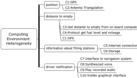
Figure 3.2: Variability in the Computing Environment
Figure 3.2 outlines the context space of the target computing environment. It contains variability contexts that are expected to occur in 4 subgoals (G1-G3 and G5) of the application.
Chapter 4
The GoalD Approach
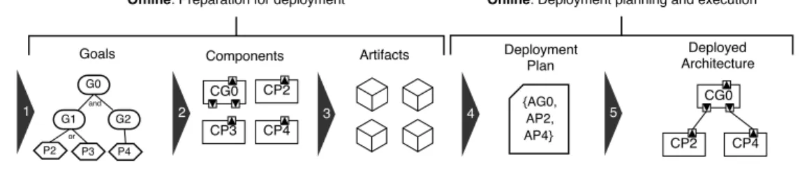
Our approach to goal-driven automated deployment (GoalD) is divided into offline and online activities. This differentiation is in line with established concepts on soft-ware development processes for variability configuration and adaptive systems (e.g., [3]). Offline activities are conducted by software engineers and result in development and pub-lishing of software components. The online activities are autonomously executed in the target environment and result in the deployment of the system. Figure 4.1 presents an overview of GoalD.
Figure 4.1: Overview of the steps in GoalD
The offline activities are conducted by software engineers and include the capturing of requirements and the development and publishing of software components to achieve them. In GoalD, the offline activities consist of: (i) requirements modeling as goals (Section 4.1.1), (ii) goal mapping to components (Section 4.1.2), and (iii) components packaging into artifacts, which are then published to a components repository (Section 4.1.3).
The online activities concern the selection and application of the components that fit the host environment. In GoalD, we aim to make this activity supported by automated reasoning and potentially embedded in the software itself. The online activities in GoalD include: (i) deployment planning, which includes automated reasoning and decision on the artifacts suitable for the target computing environment so that goals depicted in the offline activities are achieved (Section 4.2.1), and (ii) architecture deployment based on artifacts fetching and binding (Section 4.2.2).
4.1
Offline
Previously, goal-driven approaches were proposed for introducing variability at re-quirements, context modeling, software behavior, and software architecture[5][63]. In our methodology, we propose a systematic approach to support deployment variability, from requirements to deployment. Deployment variability is important since not taking into account the heterogeneity of a computing environment may lead to unnecessary or even unsuited deployment of components. Such scenario would bring a negative impact to soft-ware performance, or in some cases represent inconsistent deployment of functionalities on the target device.
When developing a monolithic software, we implement in the same codebase all func-tionalities, then all code is built and deployed together. In the Filling Station Advisor example, if implementing it as a monolithic software, the logic to get the vehicle posi-tion using GPS or antenna triangulaposi-tion would stay in the same codebase and would be deployed altogether in the target environment, even when it does not have antenna triangulation capability.
In order to better cope with heterogeneity in the computing environment, we should minimize the coupling between parts of the code that have dependencies on specific re-sources in the environment. By encapsulating dependencies of specific rere-sources into components, it is possible to create variability at architecture level. By packaging the components into different artifacts, it is possible to maintain such variability at deploy-ment level. Such variability is useful as it allows the deploydeploy-ment of components only to environment that have the required resources.
Regarding the Filling Station Advisor example, depicted in Figure 3.1, for goal G1 (Get Position), components can be implemented providing the actual position of the device by means of GPS or antenna triangulation. Such components can be packaged into different artifacts that will only be deployed when the target environment has the appropriate resources.
4.1.1
Goal Modelling
The modelling structure of GoalD is the Deployment Goal Model (DGM) a specialized version of CGM with resource notion, that specifies restrictions to the applicability of plans in relation to the deployment environment.
Definition 1 (Resource) A resource is a specific computing capability that could be available in the computing environment and used in plans. A resource receives a label.
In GoalD, the context as a description of the target computing environment is con-cretized as a set of resources. The semantics is that if the resource is present in the context, the associated computing capability is available in the target computing environment. In our example, the set [c1, c5, c8] is an example of context, representing that GPS (c1), Internet connection (c5), and voice synthesizing (c8) are capabilities that should be avail-able in the computing environment to have their related plans executed. For example, the execution of plan P1:Get position using GPS requires GPS (c1) to be available.
Plans can require resources in order to be applicable, for example, P1: get position using GPS requires the resource GPS to be available. The Deployment Goal Model
(DGM) extends a goal model with resource related restrictions to the applicability of plans.
Henceforth, we will refer to DGM as our underlying goal model structure. We formally define the DGM as follows:
Definition 2 (Deployment Goal Model) A Deployment Goal Model (DGM) is a tu-ple (M, env_res, ctx_cond) where:
• M is a design-time goal model defined as a tuple (N, R), where N is a set of goals and plans in the model, and R the corresponding set of relationship links between the elements in N.
• env_res is a set of environment resources.
• ctx_cond: R → env_res associates a relationships in R with a resource or more in env_res.
Context conditions are restrictions to the applicability of a plan and are used to solve variability at deployment. A context condition (ctx_cond) is satisfied if its associated environment resource is present in the context. For example, in a scenario with context ctx=[c1, c5], the context condition c1 is satisfied. In Figure 3.1, the goal G1:Get position has two alternatives to be achieved: by executing the plans P1:Get position using GPS or P2:Get position using antenna triangulation. The plan P1 is applicable if the context condition c1 (GPS) is satisfied, which is the case when GPS capability is available in the target environment.
4.1.2
From Goals to Components Specification
Components are units of composition with contractually specified interfaces and ex-plicit context dependencies [18]. Components and interfaces can be described using ar-chitecture description languages (ADLs). Yu et al. [63] adapt the Darwin ADL [39] with elements borrowed from one of its extensions, namely Koala [61]. They also provide a method for relating goals with components, but without taking into account context con-ditions. In GoalD, we define patterns to map CGM elements into architectural elements, which are specified as ADL elements mostly borrowed from Yu et al. proposal [63].
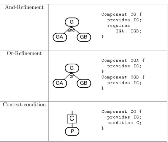
The patterns present in Table 4.1 are used to map components based on the DGM of the system. By mapping components we mean identifying which component should be developed in order to reflect the DGM of the system. By using the proposed patterns, the variability present in the DGM is kept at the architecture of the system. Theses patterns are an extension of Yu et al.[63] patterns for the Goals-Component view. We extended Yu et al.[63] patterns with context conditions. The presented patterns are described using goals but they can be applied for goals and plans without distinction.
An AND-refinement results in a components specification that realizes the achieve-ment of the parent goal by achieving all its subgoals. For an AND-refineachieve-ment, we define an AND-pattern applied as follows: (i) an interface specification for each node and (ii) a component specification that provides the node interface and requires each interface generated for each subnode of the AND-refinement.
Table 4.1: Contextual Goal Model to components - patterns And-Refinement C o m p o n e n t CG { p r o v i d e s IG ; r e q u i r e s IGA , IGB ; } Or-Refinement C o m p o n e n t CGA { p r o v i d e s IG ; } C o m p o n e n t CGB { p r o v i d e s IG ; } Context-condition C o m p o n e n t CG { p r o v i d e s IG ; c o n d i t i o n C ; }
The latter component implements a strategy to achieve its provided goal. It coordi-nates the more specific subgoals by calling them and passing one result as the input to another, when applicable. As an example, applying AND-refinement patterns for goal G4 of the Filling Station Advisor application, will result in the specifications of the interface and its respective component DecideMoreConvenient and DecideMoreConvenientImpl, requiring both interfaces GetConstraints (from plan P12 ) and ChooseFillingStation (from plan P13 ). The resulting specification follows:
i n t e r f a c e D e c i d e M o r e C o n v e n i e n t {} i n t e r f a c e G e t C o n s t r a i n t s {} i n t e r f a c e C h o o s e F i l l i n g S t a t i o n {} c o m p o n e n t D e c i d e M o r e C o n v e n i e n t I m p l { p r o v i d e s D e c i d e M o r e C o n v e n i e n t ; r e q u i r e s G e t C o n s t r a i n t s , C h o o s e F i l l i n g S t a t i o n ; }
An OR-refinement should result in one interface specification and multiple components specifications that provide the implementation of such an interface. In GoalD, the OR-pattern is applied as follows: (i) an interface specification for the OR-refined node and (ii) a component specification for each subnode providing the interface of the OR-refined node. For example, in the Filling Station Advisor, applying the patterns for G1, P1 and
P2 will result in the specification of the interface GetPosition and of the two compo-nents GetPositionUsingGPS and GetPositionUsingAntenna, both providing the inter-face GetPosition. The resulting specification is as follows:
i n t e r f a c e G e t P o s i t i o n {} c o m p o n e n t G e t P o s i t i o n U s i n g G P S { p r o v i d e s G e t P o s i t i o n ; c o n d i t i o n c1 ; } c o m p o n e n t G e t P o s i t i o n U s i n g A n t e n n a { p r o v i d e s G e t P o s i t i o n ; c o n d i t i o n c2 ; }
Differently from AND-refinements, components derived from subgoals of OR-refinements provide, i.e. implement, the interface derived from their parent node. It means that each of such implementations represents an architecture variability. At the architecture level, such variability reflects as a decoupling of their respective components, following the proposed OR-pattern.
In CGM, AND/OR-refinements can be associated with context conditions present in the CGM refinements. Such conditions are propagated to the body of the mapped components as a condition element. This is the case in the OR-refinement of G1 via P1 and P2 where the plans are associated with the context conditions c1 and c2, respectively. In particular, context conditions associated to OR-refinements restrict the applicability of the alternative strategies to the availability of different resources in the computing environment.
Using the association of an AND/OR-refinement and context conditions in the com-ponent analysis, we extend the variability present in the CGM and its conditions to the architecture of the system. For example, component GetPositionUsingGPS and GetPositionUsingAntenna provide the same goal but have different context conditions (c1 and c2). It means that we can achieve the same goal by deploying one of the two component variants given that the resources are available.
By using the proposed patterns, the variability presented in the goal model is catered for in the architecture of the system. Such variability in the architecture enables adapta-tion to the heterogeneity in the target environment. Specified components and interfaces should then be implemented as concrete components. For example, in the Java platform, interfaces and components specified in an ADL could be implemented as Java interfaces and classes.
4.1.3
Packaging Components into Artifacts
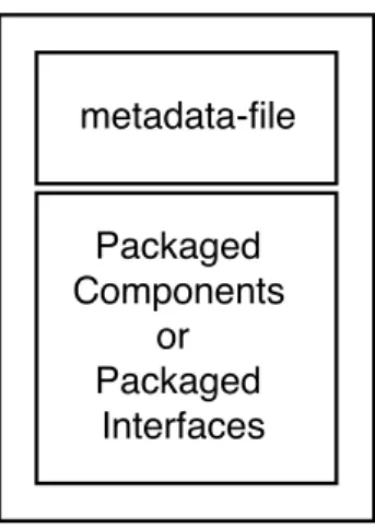
In the architecture level, goals in the CGM are contractually specified as interfaces, which in turn, are implemented by components. From the deployment point of view, components and interfaces represent deployment units and should be packaged as files for distribution. We call them artifacts. To allow automated deployment, GoalD artifacts in-clude packaged components and interfaces as well as metadata that describe the packaged elements, which can be either components or interfaces, as depicted in Figure 4.2.
Figure 4.2: Artifact Structure
Artifacts metadata describe the artifact’s goals, dependencies, and context condi-tions and are characterized by the following information: (i) name, (ii) condicondi-tions, (iii) defines, (iv) implements and (v) depends. Firstly, name metadata uniquely identifies an artifact. Secondly, conditions metadata describes the context conditions needed to deploy an artifact to a given environment. Lastly, defines, implements, and depends metadata are specified in terms of goals and used to analyze contractual responsibili-ties between artifacts: defines declare that an artifact defines the contract for a set of goals; implements declares that an artifact provides implementation for a set of goals (i.e. implements the contract declared for the goal); depends declares that an artifact has a dependency relationship towards artifacts that define and implement each of a set of goals.
All components packaged together in an artifact will be delivered together. In order to favor low coupling in the GoalD approach, components and interfaces should be packaged in separated artifacts, so they can be delivered only to environments where they are required and further used. In order to maximize the flexibility of systems following the GoalD deployment approach, we package interfaces and components in two respective artifact types: definition and implementation.
A definition artifact packages interfaces derived from the application of the patterns presented in Section 4.1.2 and, via its metadata, it declares the set of goals it provides a definition for. In a definition artifact, the metadata defines contains a list of goals it provides definition for as packaged interfaces, i.e. contracts. For example, the interface definition for goal G1 of the Filling Station Advisor, namely GetPosition, is packaged in a definition artifact along with the following metadata:
n a m e : G e t P o s i t i o n . def d e f i n e s : G e t P o s i t i o n
The implementation artifact type packages components, where the implements meta-data contains the list of goals provided by the packaged components of the artifact, speci-fied in accordance with those AND/OR-patterns in Section 4.1.2. The depends metadata contains a list of goals that packaged components depends on. For example, the com-ponent for goal G4 of the Filling Station Advisor, namely DecideMoreConvenient, is packaged in an implementation artifact along with the following metadata:
n a m e : D e c i d e M o r e C o n v e n i e n t . i m p l i m p l e m e n t s : D e c i d e M o r e C o n v e n i e n t
d e p e n d s : G e t C o n s t r a i n t s , C h o o s e F i l l i n g S t a t i o n ;
Note that DecideMoreConvenient.impl depends on the definition and implemen-tation of goals GetConstraints and ChooseFillingSimplemen-tation. Therefore, at deployment
time, components that defines and implements goals GetConstraints and ChooseFillingStation should be included in order to successfully deploy DecideMoreConvenient.impl artifact.
Finally, the condition metadata of implementation artifacts reflects the context con-ditions of packaged components. For example, in the Filling Station Advisor, the compo-nents GetPositionUsingGPS and GetPositionUsingAntenna are packaged into separate artifacts with the following metadata:
n a m e : G e t P o s i t i o n U s i n g G P S . i m p l i m p l e m e n t s : G e t P o s i t i o n c o n d i t i o n s : c1 n a m e : G e t P o s i t i o n U s i n g A n t e n n a . im p l i m p l e m e n t s : G e t P o s i t i o n c o n d i t i o n s : c2
GetPositionUsingGPS and GetPositionUsingAntenna are artifacts that implement the same goal GetPosition and can be deployed in different contexts, keeping at deploy-ment level the variability introduced by the CGM as well as the decoupling following the patterns applied in previous Section 4.1.2.
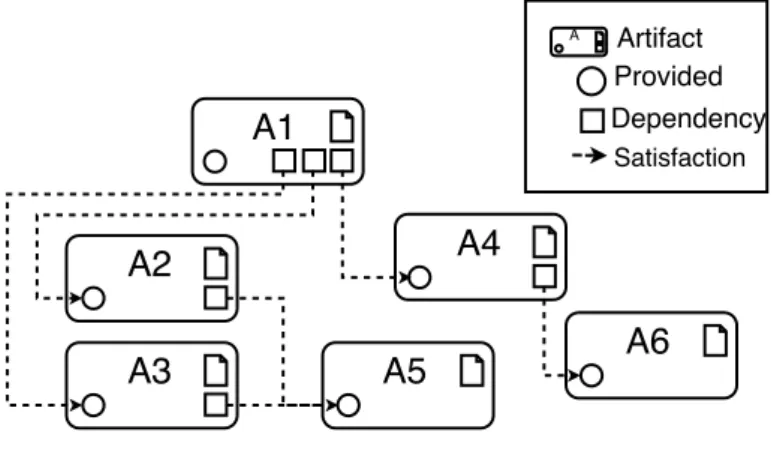
Artifacts forms dependency trees. Figure 4.3 depicts the dependency relationship between artifacts. A1 is a root interface and have 3 dependencies, that are provides by A2, A3 and A4. A2 and A3 have one common dependency, provided by A5. A5 and A6 have no dependencies.
Figure 4.3: Dependency graph
After components and their corresponding metadata information are packaged accord-ingly into artifacts, they are registered in a repository so that they can be distributed to the target environment. In the registration process, an artifact is uploaded to the reposi-tory, its metadata is processed and registered in the repository database, where they can be queried in the next step of GoalD: the deployment planning.
4.1.4
Development Process
In previous subsections we proposed techniques to support the design of software with variability from requirements to deployment. In this section we present activities to apply such techniques in a software development process.
Roles
The proposed process considers three roles: users, requirements engineers and software architects. Figure 4.4 summarizes the collaboration between the roles.
Figure 4.4: Roles collaboration
User This role has access to a particular computing environment and wants to achieve some goals there.
Requirements Engineer Is responsible for translating users goals to a goal model. Also is responsible for analyzing the different contexts that the system is meant to operate and how they affect the goals, defining the DGM of the system.
Architect Projects the software architecture so as to permit variability of deployment. From the point of view of dynamic heterogeneous computing environments, the focus is to create interfaces for components that can allow for goal achievements using different computing resources.
4.1.5
Activities
Figure 4.5 describes the development process activities. Goal Modeling
This phase is coordinated by a requirements engineer with the participation of a do-main specialist, possibly the user. In this activity a goal model is created. At the goal
Figure 4.5: Deployment Process Activities
model it is identified the solution space, what the system should achieve, and possible strategies to achieve the goals. Also, the goal model creates a common language between users and software engineers. In this activity, relevant resources should be identified and the goal model should be annotated with context conditions related to the computing environment using the formalism described in Section 4.1.1.
Component Analysis
The architect is the responsible for this activity. It receives as input a DGM. Then, variability points, components and its interfaces are identified. Component interfaces are created following the guidelines described in Section 4.1.2.
Component Development
The architect is the responsible for this activity. Component development includes the coding, build and test of software components. Then, components are package into artifacts and put in the repository as described in Section 4.1.3.
4.2
Online
In the online part of the approach, the artifacts present in the repository are au-tonomously deployed to the target computing environment.
Figure 4.6 depicts the online activities. In the first step, a user interested in using a computing environment to achieve a set of goals submits to such environment which goals it wants to achieve in the form of a deployment request. In the second step, the target environment realizes a deploymeng planning by analyzing the available computing resources and artifacts present in the repository, then generating a deployment plan: a selection of artifacts that can allow for the goals achievement in the available computing environment. Finally, the deployment is executed by fetching the selected artifacts from the repositories and binding them.
Figure 4.6: Goald Autonomic Deployment
After components and their corresponding metadata information are packaged accord-ingly into artifacts, they are registered in a repository so that they can be distributed to the target environment. In the registration process, an artifact is uploaded to the reposi-tory, its metadata is processed and registered in the repository database, where they can be queried in the next step of GoalD: the deployment planning.
4.2.1
Automated Deployment Planning
In the online part of the approach, the focus is on the automated deployment planning of the artifacts present in the components repository. In order to carry out such planning, the stakeholders explicitly define a set of goals to be achieved in a computing environment as a deployment request. Then, the target environment realizes a deployment planning by analyzing the available computing resources and artifacts present in the repository. The deployment plan consists of a selection of artifacts that can allow for the goals achievement relying on the available computing environment. Finally, the deployment is executed by fetching the selected artifacts from the repositories and binding them.
Prior to presenting GoalD’s approach to automated deployment planning, we present GoalD’s deployment metamodel in the following Section 4.2.1 as the underlying structure that defines major conceptual elements of GoalD’s automated deployment. Then we present the algorithm in Section 4.2.1 to automate the deployment planning.
Metamodel
The metamodel of GoalD consists of six major elements: (1)Goal, (2)Artifact, (3)Agent, (4)Repository, (5)Deployment Request, and (6)Deployment Plan. Figure 4.7 presents the GoalD metamodel.
Artifact is the central entity at deployment level. As described in Section 4.1.3, ar-tifacts have conditions, defines, implements, and depends which create inter-relations
amongst artifacts, so that an artifact that has a goal dependency is dependent on an artifact that provides definition and implementation for such a goal. An artifact is de-ployable if all its context conditions and dependencies are satisfiable. Goals are achievable if their artifacts are deployable as part of a deployment plan to achieve such goals. The Agent can accept deployment requests, an action that should trigger the deployment plan-ning. An agent knows the repository where it looks for artifacts. A repository has a set of artifacts that it can be queried about by the queryForArtifacts method, which receives a goal as argument and returns all artifacts in the repository providing that goal. An agent can verify conditions of an artifact by evoking the isSatisfied method for it. The Deployment Request is a set of goals that an external entity sends to an agent, requesting it to plan a deployment. Agent ’s doPlanDeployment method returns a Deployment Plan, which is a set of artifacts that provides the goals specified in the Deployment Request. Finally, a Deployment Plan is composed of a set of artifacts that realizes a set of goals in a
Figure 4.7: The GoalD Deployment metamodel
certain computing environment. The plan of such deployment is devised by the algorithm further presented in the next section.
Planning Algorithm
To come up with a deployment plan for a given deployment request and context, we present Algorithm 1. It implements the Agent ’s doPlanDeployment method of the GoalD
metamodel.
Algorithm 1 works as follows: it receives a deployment request as a parameter, which contains a list of goals. For each goal in the list, it queries the repository for an artifact that provides definition of the goal (line 4). If no definition is found, the algorithm returns NULL (line 6). Otherwise, the returned definition is included in a sub-plan (line 9) and the repository in queried for implementations (line 11). Next, the repository returns a list of artifacts. For each artifact, the algorithm looks for a sub-plan for such an artifact (lines 12-30). First, the context conditions are verified (line 13). If the context is satisfied (line 14), a new plan is created with the artifact (lines 15-16). If the list of dependencies of the artifact is empty (line 17), the new plan is added to the sub-plan (line 18). Else, if the artifact has dependencies, the algorithm is recursively called for these dependencies. If the result of the recursive call is not NULL (line 23), the resulting plan is added to the new plan and included into the sub-plan (lines 24-25). In both cases that new plan is added to a sub-plan, the look for a deployment plan that satisfies the selected goal is over and the inner for loop is halted (lines 19 and 26) and then the sub-plan is added to the resulting plan (line 32). Otherwise, if the conditions evaluation (line 13) returns FALSE or the recursive call returns NULL, the artifact can not be deployed. The loops continue for the other artifacts. If after all tries the sub-plan is EMPTY (line 34), the deployment for the selected goal is not possible, and the algorithm returns NULL (line 35). Note that the algorithm will return NULL if for any of the goals in the request it is not possible to come up with a plan. Otherwise, the algorithm will return a valid plan.
We should note that deployment plan is valid for a given context if: (i) for each artifact in the plan, all context conditions hold, (ii) for each dependency in a plan, there is at least one component within the plan that defines and one that implements the dependency. A deployment plan is complete if, for each goal in the request, there is at least one fulfilling artifact in the deployment plan. A deployment plan satisfies a deployment request if it is valid, and complete.
Being so, we can verify if a deployment plan satisfies a deployment request by executing the following steps that verify such properties: (i) check if for all selected artifacts, all context conditions are met; (ii) check if for all selected artifacts, the dependencies are within the deployment plan; (iii) check if for all goals in the deployment request there is at least one artifact that declares each intended goal and one that provides such goal.
• Check if for all selected artifacts, all context conditions are met.
• Check if for all selected artifacts, the dependencies are within the deployment plan. • Check if for all goals in the deployment request there is at least one artifact that
declares each intended goal and one that provides such goal.
4.2.2
Deployment Execution
Once the deployment plan has been devised in GoalD, the deployment execution will become ready to take place. The execution involves (i) fetching the artifacts present in the deployment plan from the repository to the target environment, and (ii) binding the components present into such artifacts, creating the application runtime architecture. The binding can then use alternative ways to bind between client objects to their re-quested implementation service at runtime. Using reflexive platforms allows eliminating
Input: DeploymentRequest request Result: DeploymentPlan plan
1 var resultingPlan ← new DeploymentPlan() 2 foreach Goal selectedGoal in request.goals do 3 var subPlan ← new DeploymentPlan() 4 var definition ← repository.
queryForDefinition(selectedGoal)
5 if definition == NULL then 6 return NULL
7 end
8 else
9 subPlan.add(definition);
10 end
11 var artifacts ← repository.
queryForImplementation(selectedGoal)
12 foreach Artifact artifact in artifacts do 13 var contextSatisfaction ←
isSatisfied(artifact.conditions)
14 if contextSatisfaction then
15 var plan ← new DeploymentPlan () 16 plan.add(artifact)
17 if artifact.depends == EMPTY then 18 subPlan.add(plan)
19 break
20 end
21 else
22 var depPlan ← doPlanDeployment (artifact.depends) 23 if depPlan != NULL then
24 plan.add(depPlan) 25 subPlan.add(plan) 26 break 27 end 28 end 29 end 30 end
31 if subPlan != EMPTY then 32 resultingPlan.add(subPlan) 33 end 34 else 35 return NULL 36 end 37 end 38 return resultingPlan
![Figure 2.1: Context-aware services framework by [24]](https://thumb-eu.123doks.com/thumbv2/123dok_br/18835354.928341/14.892.173.697.586.838/figure-context-aware-services-framework-by.webp)
![Figure 2.3: A Life-cycle model for Self-Adaptive Software System[3]](https://thumb-eu.123doks.com/thumbv2/123dok_br/18835354.928341/16.892.120.761.485.787/figure-life-cycle-model-self-adaptive-software.webp)