Technical Document 2760
April 1995
High Frequency (HF)
Automatic Link
Establishment (ALE)
Transition Plan
EXECUTIVE SUMMARY
Power projection/littoral warfare operations, as articulated in “From the Sea....,” depend heavily on reliable inter-/intra-force connectivity, both in dominating the littoral battle space in preparation for amphibious warfare and during the critical transition ashore when ship-to-beach connectivity is essential to ensuring all forces share a common tactical picture. Key to meeting these connectivity requirements are automated High Frequency (HF) communications systems capable of agile fre-quency selection, automated circuit establishment, and channel monitoring.
This paper articulates an HF ALE Transition Plan which.
1. Describes an evolutionary HF Automated Link Establishment (ALE) technology transition pro-cess that points toward HF 2000, a modern, automated HF communications system that man-ages resources to optimize data throughput and minimize operator intervention while maintain-ing reliable connectivity in even the noisiest environments; and
2. Delineates a prioritized ALE implementation plan which transitions Navy to an inter-/intra-BattleGroup (BG)/Amphibious Ready Group (ARG) ALE capability which meets Joint/Allied/ NATO interoperability requirements.
The HF ALE Transition Plan was developed through the process of:
1. Analyzing BG and ARG communications plans and circuit requirements. 2. Establishing criteria to determine a circuit’s suitability for ALE.
3. Identifying circuits in typical BG/ARG communications plans which are potential candidates for ALE.
4. Analyzing HF communications technologies to develop configuration options.
5. Establishing platform implementation priorities based on warfare tasking and command sup-port requirements.
6. Reviewing budgetary plans for acquisition and installation.
7. Identifying preferred implementation options that would satisfy operational, technical and affordability requirements.
8. Time sequencing recommended options to execute the most cost-effective transition of ALE into the fleet.
The HF ALE Transition Plan presented is therefore based on the full, broadband,
CONTENTS
SECTION ONE . . . 1Ć1
INTRODUCTION . . . 1Ć1
1.0 INTRODUCTION . . . 1Ć1 1.1 BACKGROUND. . . 1Ć1 1.2 ALE TRANSITION PLAN . . . 1Ć3
SECTION TWO . . . 2Ć1
ALE OPTIONS. . . 2Ć1
2.1 OVERVIEW . . . 2Ć1 2.2 ALE SUPPORT RULES AND TECHNICAL
REQUIREMENTS . . . 2Ć1 2.2.1 ALE Rules of Operation . . . 2Ć2 2.2.2 Technical Capability Required to Support ALE . . . 2Ć2 2.3 HF TRANSMISSION CHARACTERISTICS. . . 2Ć3 2.3.1 Frequency and Antenna Radiation Patterns . . . 2Ć3 2.3.2 Environmental Factors Affecting HF Skywave Propagation . . . 2Ć4 2.4 ALE OPTIONS (1Ć4) . . . 2Ć5 2.4.1 Option 1: Automatic ALE Transceiver Subsystem . . . 2Ć6 2.4.2 Option 2: ALE Modem/Controller . . . 2Ć7 2.4.3 Option 3: Broad band Receiving Subsystem (with
2.6 OPTION TRADEĆOFFS . . . 2Ć17 2.6.1 Option 1 TradeĆOffs. . . 2Ć17 2.6.2 Option 3 TradeĆOffs. . . 2Ć18 2.6.3 Option 4 TradeĆOffs. . . 2Ć19 2.7 ALE OPTIONS AS POTENTIAL SOLUTIONS . . . 2Ć19 SECTION THREE . . . 3Ć1
ALE TRANSITION PLAN . . . 3Ć1
3.1 OVERVIEW . . . 3Ć1 3.2 ALE IMPLEMENTATION PRIORITIES. . . 3Ć1 3.3 ALE TRANSITION PLAN PROCESS . . . 3Ć2 3.3.1 POM ALE Transition Plan . . . 3Ć3 3.3.2 HF ALE Transition Plan . . . 3Ć4 3.4 ALE TRANSITION PLAN . . . 3Ć5 3.5 ALE OPERATIONS . . . 3Ć6 3.5.1 Broad band ALE Operations . . . 3Ć7 3.5.2 NonĆBroadband ALE Operations . . . 3Ć7 3.6 THE NEXT STEP: ALE CONCEPT OF OPERATIONS . . . 3Ć8 APPENDIX A: ACRONYMS . . . AĆ1
APPENDIX B: BIBLIOGRAPHY . . . BĆ1
APPENDIX C: COMMUNICATIONS PLANS . . . CĆ1
C.1 COMMUNICATIONS PLANS . . . CĆ1 APPENDIX D: SHIPBOARD EQUIPMENT . . . DĆ1
D.2.3 LHA Narrowband HF Configuration . . . DĆ3 D.2.4 CV Narrowband HF Configuration . . . DĆ3 D.3 BROADBAND EQUIPMENT . . . DĆ4 D.3.1 Existing Broad band Equipment . . . DĆ5 D.3.2 New Ship Broadband Equipment. . . DĆ5 D.4 HF EQUIPMENT SUMMARY . . . DĆ6
APPENDIX E: CONFIGURATION ANALYSIS . . . EĆ1
E.1 ALE TRANSITION OPTIONS. . . EĆ1 E.2 OPTION 4 (BROADBAND SYSTEM) ONLY. . . EĆ1
E.3 OPTION 3D (BROADBAND RECEIVING SUBSYSTEM) ONLY. . . . EĆ2
E.4 OPTION 3E (BROADBAND RECEIVING SUBSYSTEMĊ
AN/SRAĆ49 AND PRESELECTOR CONFIGURATION) ONLY . . . EĆ2
E.5 COMBINATION OF OPTION 4 (BROADBAND SYSTEM)
AND OPTION 3D (BROADBAND RECEIVING SUBSYSTEM) . . . EĆ2
E.6 COMBINATION OF OPTION 4 AND OPTION 3E
BROADBAND RECEIVING SUBSYSTEMĊAN/SRAĆ49 AND
PREĆSELECTOR CONFIGURATION) . . . EĆ3
E.7 COMBINATION OF OPTION 4 AND OPTION 1 (AUTOMATIC
ALE TRANSCEIVER SUBSYSTEM) . . . EĆ3
E.8 COMBINATION OF OPTION 4, OPTION 3E (BROADBAND
RECEIVING SUBSYSTEMĊAN/SRAĆ49 AND PREĆSELECTOR CONFIGURATION) AND OPTION 1 (AUTOMATIC ALE
TRANSCEIVER SUBSYSTEM) . . . EĆ3
FIGURES
2Ć6. Option 3B broadband receiving subsystem . . . 2Ć9
2Ć7. Option 3C broadband receiving subsystem . . . 2Ć10
2Ć8. Option 3D broadband receiving subsystem . . . 2Ć11
2Ć9. Option 3D broadband receiving subsystem . . . 2Ć11
2Ć10. Option 3D broadband receiving subsystem . . . 2Ć13
DĆ1. Generic narrowband HF system. . . DĆ2
DĆ2. Generic broadband HF system. . . DĆ5
TABLES
2Ć1. Operational rules for ALE . . . 2Ć14
2Ć2. Technical requirements for ALE . . . 2Ć15
2Ć3. Technical requirements for ALE . . . 2Ć16
2Ć4. Limitations of ALE options . . . 2Ć17
3Ć1. ALE platform priorities . . . 3Ć2
3Ć2. POM installation plan. . . 3Ć4
3Ć3. HF ALE transition plan (modified POM) . . . 3Ć6
CĆ1. Desert Shield/Desert Storm communications plan. . . CĆ2
CĆ2. ARG communications plan. . . CĆ6
SECTION ONE
INTRODUCTION
1.0 INTRODUCTION
Power projection/littoral warfare operations, as articulated in “From the Sea [reference (1)], depend heavily on reliable inter-/intra-force connectivity, both in dominating the littoral battlespace in prepa-ration for amphibious warfare and during the critical transition ashore when ship-to-beach connectiv-ity is essential to ensuring all forces share a common tactical picture.
In addition to a common tactical picture, the Commander, Joint Task Force (CJTF)/Expeditionary Force Commander requires reliable Joint C4I connectivity, with flexibility from short range to nearly global, and interoperability with multiple C4I and combat support systems. Key to meeting these con-nectivity requirements are automated HF communications systems capable of agile frequency selec-tion, automated circuit establishment, and channel monitoring.
1.1 BACKGROUND
HF communications plays a vital role in providing the tactical communications required to ensure success in Navy, Joint, and Allied military operations [reference (2) and (3)]. Indeed, in a typical Battle Group/Amphibious Ready Group’s Communications Plan, approximately 30 to 40 percent of the specified circuits are either an HF primary circuit or an HF secondary circuit [Appendix C]. It is, however, a challenging and demanding frequency spectrum in which to operate, from both a technical and warfighting perspective.
To meet the warfighting requirements of “From the Sea...,” HF communications, as with any deployed communications system, must incorporate the technical advances that have occurred in the past 10-20 years. To this end, a structured approach to the improvement of existing HF communica-tions and the development and/or consideration of new HF communicacommunica-tions capability through technology insertion, technology integration, and technology demonstration is underway. The pur-pose is twofold: (1) to test technical feasibility in an operational environment at minimal cost, and (2) to provide Battle Group and Amphibious Ready Group Commanders the warfighting capabilities of leading-edge technologies as they emerge (or are developed). A number of initiatives have been undertaken and significant improvements in HF system performance demonstrated in the past three/ four years, including the successful use of Automatic Link Establishment (ALE) equipment and pro-cedures out to several thousand miles [reference (4)].
ALE is designed as an integral part of establishing and maintaining communications connectivity. A link is automatically established with the responding unit when a usable frequency is identified. When the link degrades or becomes unusable, ALE can be manually directed to reestablish that link. When utilized in its full capacity, ALE makes circuit establishment transparent to the user. When used as a support tool, ALE can be used to monitor the frequency spectrum and assist in finding clear fre-quencies.
In 1990, ALE supported HF communications was successfully used to automatically test several frequencies assigned for use between the USS Iwo Jima (LPH-2) and the Naval Communications
between USS Tarawa (LHA-1) and the Naval Communications Station (NAVCOMSTA), Diego Gar-cia, while USS Tarawa was deployed to the Western Pacific and the Indian Ocean. ALE was used to
automatically test and select the optimum HF channel from among the assigned frequencies and establish connectivity between USS Tarawa and the serving NAVCOMSTA [reference (6)].
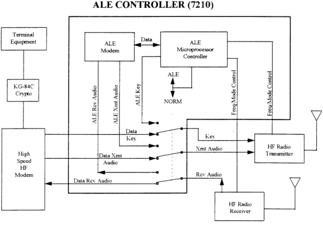
During a three-month period, from 1 July through 15 October 1992, the ship passed virtually all traffic over the ALE system. Actual record traffic throughput was measured at 600 bps via Harris Model 5254C modems, which were interfaced to KG-84C encryption devices and standard data ter-minal equipment. ALE-supported HF communications proved to be extremely reliable and effective. Test results showed that narrative traffic was received virtually error-free, and that communications were able to be maintained over paths previously considered unworkable with existing shipboard equipment and techniques. The block diagram of the radio system used aboard USS Tarawa is shown
in Figure 1-1.
Figure 1-1. USS Tarawa ALE equipment configuration.
These demonstrations confirmed that ALE could help solve many of the current HF communica-tions limitacommunica-tions by automatically determining which frequencies are available in the existing propa-gation environment, automatically establishing connectivity on the best of the allocated frequencies, automatically monitoring the performance of all assigned frequencies, and maintaining a profile on the status of all the available frequencies.
ALE integration into the Fleet could also make contributions to interoperability. The Marine Corps has an ALE capability in the AN/TSC-120, a shelter-mounted mobile communications system that interfaces to the Defense Communications System (DCS) and Automated Digital Information Net-work (AUTODIN) netNet-works and supports Expeditionary Forces ashore with connectivity to forces afloat. The Army has a similar system, the AN/TSC122, with similar capabilities, and, the Air Force has initiated a full ALE capability in their command center upgrade program (Scope Command) and in Air Mobile Command (AMC) aircraft and ground support sites.
specific services. Multiple HF frequencies are assigned to each HF service to guarantee that there are sufficient frequencies in each portion of the HF spectrum to ensure at least one channel will be avail-able to support forcewide connectivity. With ALE, all frequencies may be considered as resources and assigned to a frequency pool from which ALE can then assign the best frequencies to support services on a prioritized basis. Additionally, with proper coordination and planning, ALE can use one set of exciters to support more than one circuit if circuit usage on both circuits is low and exciter tun-ing is rapid.
The question to be answered is: “Can the Navy transition HF ALE into the Fleet within current and near-term budget constraints?”
1.2 ALE TRANSITION PLAN
SECTION TWO
ALE OPTIONS
2.1 OVERVIEW
ALE implementation is a complex issue that requires multiple considerations before selection of an optimum ALE configuration. In this section, the issues considered include the standards that govern ALE, the impact of antenna patterns and the propagation environment on ALE, and the ALE configu-rations options.
ALE equipment includes an ALE Modem/Controller (ALEM/C), a scanning receiver, an operator’s terminal, and ship radio equipment, including antennas, couplers and transmitters/receivers (Fig-ure 2-1 refers). ALE systems test the RF environment for clear channels by exchanging Link Quality Analysis (LQA) “handshakes.” When a useable frequency is found, it automatically establishes con-nectivity on that frequency. When the net is not being used, or when directed, the ALE receiver scans up to 100 pre-defined channels and exchanges LQA messages with other ALE stations. The result of the “handshake” is given a score and is stored so that if an operating channel becomes unusable, the next best channel (based on score) can be selected and connectivity re-established.
Figure 2-1. ALE modem controller.
2.2 ALE SUPPORT RULES AND TECHNICAL REQUIREMENTS
2.2.1 ALE Rules of Operation
ALE Rules of Operation are classified as either “Critical” or “Conditional.” “Critical” rules are those to which an ALE system must adhere to ensure ALE interoperability. “Conditional” rules are those which the operator may incorporate or enforce as dictated by operational necessity.
Rule 1. Independent ALE receiver capability (in parallel with any other)— CRITI-CAL.
Rule 2. Always listens (for ALE signals)—CRITICAL.
Rule 3. Always will respond (unless deliberately inhibited)—CONDITIONAL.
Rule 4. Always scanning (if not otherwise in use)—CONDITIONAL.
Rule 5. Will not interfere with active ALE frequency (unless have priority or forced)—CONDITIONAL.
Rule 6. Always will exchange LQA with other stations when requested (unless inhibited), and always measures the signal quality of others—CONDITIONAL. Rule 7. Will respond in pre-set/directed time slot (net/group/special
calls)—CONDITIONAL.
Rule 8. Always seek (unless inhibited) and maintain track of their connectivities with others—CONDITIONAL.
Rule 9. Linking ALE stations employs highest mutual level of
capability—CONDI-TIONAL.
Rule 10. Minimizes time on frequency—CONDITIONAL.
Rule 11. Minimizes power used (as capable)—CONDITIONAL.
2.2.2 Technical Capability Required to Support ALE
To support ALE, the following technical requirements, derived from the above rules, must be met or supported by equipment (e.g., transmitters, receivers, couplers) for MIL-STD-l88-141A ALE com-pliance:
S An automatic transmitting and receiving capability must be available to support ALE frequency monitoring.
S ALE systems need to be on-line at all times and be in the “listening” mode for incoming LQAs. Failure to be in the listening mode would prevent the system from being alerted to incoming LQAs and to respond to the LQAs, thereby defeating the purpose of ALE.
S As part of being in the listening mode, the ALE receiver must be able to scan the assigned fre-quencies for the incoming LQAs.
S Upon receipt of an LQA signal, ALE must be able to respond automatically to perform the two-way link analysis.
S To avoid interference with a frequency that is already in use, ALE must ignore the active fre-quency unless otherwise forced to monitor it or it has a higher priority.
S To minimize the time to respond during an ALE call, the ALE receiver must be remotely tun-able to new frequencies for scanning the pre-selected frequencies. The dwell time between the frequencies must be controllable. Transmitters must be remotely tunable to respond on the “calling” frequency.
S Transmitters, receivers, and couplers that support ALE must be tunable at speeds that can meet operational circuit establishment time criteria, which are more stringent than the technical requirements of the MIL-STD. The scanning receiver must be able to support scanning two frequencies per second, minimum, to meet MIL-STD criteria.
S To support LQA responses, transmitter must be rapidly tunable, automatically, to the called fre-quencies.
S Develop and maintain a database profile of usable frequencies in the ALE modem/controller. S Consideration must be given to HF transmission characteristics, existing equipment
configura-tions, equipment compatibility requirements, and interoperability requirements.
2.3 HF TRANSMISSION CHARACTERISTICS
HF transmission characteristics must be considered when assessing ALE options, e.g. the transmit-ting environment, the time of day, the East-West distance between communicatransmit-ting stations, the fre-quency channels allocated to the circuit, and the platform HF communications equipment configura-tions, including the antenna placement. The most critical to ALE are the relationship between frequency and antenna radiation patterns, and the effects of the environment on HF propagation.
2.3.1 Frequency and Antenna Radiation Patterns
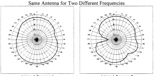
Antenna radiation patterns are areas in space where energy is radiated from an antenna. An anten-na’s coverage is a function of frequency, location, and the physical environment around it. As the fre-quency of transmission is lowered, the angle of transmission increases. As a result, identical antennas transmitting at different frequencies will create different antenna radiation patterns. Figure 2-2(A) shows the same antenna operating at two different frequencies.
The physical topography of the area in which an antenna is mounted also plays an important role in antenna radiation patterns. Physical structures in the vicinity of the antenna and the height of the antenna above the surface will cause interference patterns to form lobes and nulls in the antenna cov-erage. Antenna coverage can be modified by the reflections from the ocean and the superstructure in the antennas vicinity. Other factors that affect the radiation patterns include the antenna orientation (polarization), the groundplane material and the surface over which the signal is radiated. Salt water presents the best surface for groundwave coverage, while dry sand and rocks are the worst surface to extend coverage across.
Figure 2-2. (A) Antenna radiation patterns.
Figure 2-2. (B) Antenna radiation patterns.
These diagrams illustrate the effects of antenna radiation patterns and the relationship between antenna properties and frequencies. For ALE to function effectively, it is preferable to use the same antenna for establishing connectivity and communications.
2.3.2 Environmental Factors Affecting HF Skywave Propagation
Some environmental conditions are predictable and occur on a periodic basis, e.g., changing iono-spheric layer; while others occur in a random manner. The effects of these conditions may vary from the originating point to the endpoint as well as anywhere in between. Any changes in these conditions affect the HF communications path between users. Although these factors are not controllable, they must be taken into account when attempting to establish communications connectivity. The following are some of major environmental factors that affect HF skywave propagation:
S Sunspot Activity: Sunspot activity affects HF propagation over long haul and Near VerticalIn-cidence Skywave (NVIS) paths by changing ionization of the various ionization layers. This makes the paths very frequency-sensitive, which results in a requirement for more frequent fre-quency shifts.
S Sudden Ionosphere Disturbances (SIDs): SIDs and magnetic storms both cause skywave
prop-agation disturbances and raise background “noise” levels, as well as affecting the ionization layers. SIDs can cause some HF paths to drop out completely without warning for a period of time.
All of these various factors complicate establishing and maintaining HF connectivity between plat-forms. For any given group of frequencies, there will be a full range of usable to unusable cies. Thus, to ensure prompt connectivity, there must be some means of determining which frequen-cies are usable at any given time. Traditionally, operator experience filled that void, but a more reliable method, e.g., Communications Decision Aids (CDAs), needs to be in place to support inexpe-rienced operators. Additionally, although ALE can help in selecting frequencies, if operation involves passing off a frequency to another antenna, it can affect the usefulness of the selected frequency.
2.4 ALE OPTIONS (1-4)
NRaD Technical Document (TD) 2575, “Shipboard Implementation and Concept of Operations for Automatic Link Establishment,” [reference (9)], identifies four categories of options as potential equipment configurations for implementing an HF ALE capability in the Fleet. These options are identified based on the degree of integration with existing components or future HF communication equipments:
1. Automatic ALE Transceiver Subsystem: This is a stand-alone configuration that includes adding an automatic transceiver, automatic antenna coupler ALE modem/controller (ALEM/C), and operator’s terminal to existing shipboard HF equipment and using an existing 35-foot whip antenna.
2. ALE Modem/Controller: This option integrates an ALEM/C and operator’s terminal into the existing shipboard HF equipment. This option seeks to integrate ALE with manually tuned equipments (e.g., transmitters and couplers) while proposing only minimal changes to existing communications configurations.
3. Broadband Receiving Subsystem: This option utilizes a broadband receiving subsystem with integrated receiver or a broadband like configuration such as that of the AN/SRA-49 multi-coupler where there are a number of pre-tuned port on the multimulti-coupler. This option adds scan-ning receiver(s), ALEM/C(s), and operator’s terminal(s). There are five different configurations that comprise this option, each differing in the manner in which the receivers and modem/con-troller are integrated into the receiving subsystem. The transmitting side of this option is char-acterized by manually tuned transmitters.
4. Broadband System: This option utilizes a full broadband system to support ALE functions. This option integrates the ALEM/C into the system controller to remotely control the broad-band transmitting subsystem and the broadbroad-band receiving subsystem. This option would also be the result of adding a broadband transmitting subsystem to the broadband receiving subsys-tem with an ALE capability such as the one identified for Option 3.
In all cases, these equipment configurations use common fleet equipment, with minor modifica-tions (see Appendix D). Each of these opmodifica-tions, with variation, are presented in the following para-graphs, with advantages and disadvantage noted.
2.4.1 Option 1: Automatic ALE Transceiver Subsystem
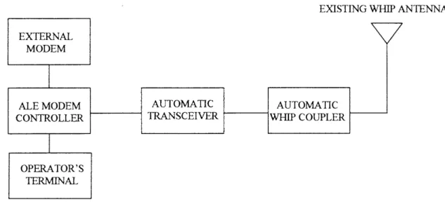
Option 1 uses an automatic ALE transceiver subsystem with an automatic antenna coupler, an existing ship whip antenna, an ALEM/C, and an operator’s terminal. This configuration provides full ALE capability to one circuit, or it could also be used to support multiple services by connecting to the modem through a switch matrix to select a communication service. In the latter case, the configu-ration can operate as a stand-alone frequency monitor to provide guidance on the availability of con-nectivity on allocated HF frequencies, though concon-nectivity is not assured due to differences in antenna patterns. In either case, the ALE functionally supports only one circuit at a time. (Figure 2-3 illustrates Option 1.)
Figure 2-3. Option 1 automatic ALE transceiver. Advantages:
S Provides a full ALE capability.
S Has minimal impact on the existing HF communications suite.
S Can be integrated into an HF communications suite and provide the ALE capability for one communications circuit.
Disadvantages:
S When providing frequency selection guidance for other circuits, the differences in antenna pat-terns may negate connectivity.
S Not a typical shipboard installation. Could result in electromagnetic interference (EMI) to the receive side of a circuit.
2.4.2 Option 2: ALE Modem/Controller
Option 2 integrates an ALE subsystem with a narrowband receiving multicoupler and a transmitter. This option uses an ALE modem/controller that is supported by a multicoupler such as an AN/ SRA-49 with pre-selected frequencies, a transmit switching matrix, and manually tuned transmitters. It is designed to scan a single pre-selected frequency for LQA signals. As such, a single port of the multicoupler, the receiver, and the transmitter are pre-tuned to a specific frequency. In order to detect an ALE LQA signal, an ALE modem/controller uses a receiver to scan the pre-selected frequency from the assigned port in the multicoupler. Upon receipt of an LQA signal, the operator terminal reg-isters an alert of a link attempt for a given frequency. The ALEM/C responds to the LQA signal with the pre-tuned transmitter on that preselected frequency. This option, like Option 1, will support only one circuit at a time. (Figure 2-4 illustrates Option 2.)
Figure 2-4. Option 2 ALE modem/controller. Advantages:
S Provides a limited ALE capability for a particular communication circuit.
S Has minimal impact on existing HF communications suite.
S Uses same antennas for ALE and communications circuits.
S Has minimum cost for an ALE capability.
Disadvantages:
S Limited to scanning only one frequency for LQA signals.
S Takes considerable time, in the order of minutes to possibly tens of minutes, to evaluate several possible frequencies for a communication circuit or circuits due to the requirement to retune or repatch the multicoupler, as well as manually tune the transmitter.
2.4.3 Option 3: Broad band Receiving Subsystem (with variations A - E)
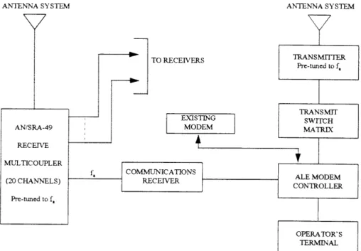
Option 3 utilizes a broadband or a broadband-like receive capability to support ALE. There are five possible configurations for this option. The first three configurations can be achieved by providing an ALE scanning receiver access to the 20 pre-tuned frequencies of the AN/SRA-49 receiving multi-coupler, which functions as a pre-selector. The fourth configuration uses a broadband receiving sub-system (similar to the subsub-system incorporated into the AN/URC109 or the AN/URC-13 1) in place of, or in addition to, the existing receiving subsystem. The fifth configuration uses an AN/SRA-49 multicoupler and an RF pre-selector such as the RF-59 l for providing the signal input to the scanning receiver. All configurations require an ALEM/C and an operator’s terminal, a scanning receiver, and a manual transmit subsystem for link establishment.
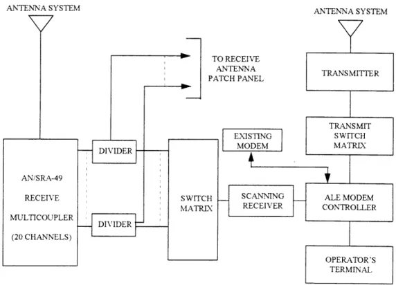
2.4.3.1 Option 3A of Broadband Receiving Subsystem. Option 3A uses an ALE modem/con-troller supported by a multicoupler such as a AN/SRA-49 with multiple channel outputs, dividers, a switching matrix, and manually tuned transmitters. The scanning receiver scans the output of the pre-tuned multicoupler ports via the switched matrix to detect an LQA signal. Upon receipt of an LQA signal, the operator terminal registers an alert for the “called” frequency. The operator must then select an available transmitter via the transmit switch matrix and manually tune the transmitter to the proper frequency to respond to the LQA signal the next time it cycles around. (Figure 2-5 illustrates Option 3A.)
Figure 2-5. Option 3A broadband receiving subsystem.
multiplexed signal is passed on to the scanning receiver where it can monitor all of the pre-selected frequencies from only one port. The multiplexed signal is also available at the receiver multicoupler patch panel for routing of active circuits to receivers for signal processing. Upon receipt of an LQA signal, the operator terminal registers an alert of a link attempt for a given frequency. The operator is then required to select a transmitter via the transmit switch matrix and manually tune the transmitter to the proper frequency to respond to the LQA signal the next time that it cycles around. (Figure 2-6 illustrates Option 3B.)
Figure 2-6. Option 3B broadband receiving subsystem.
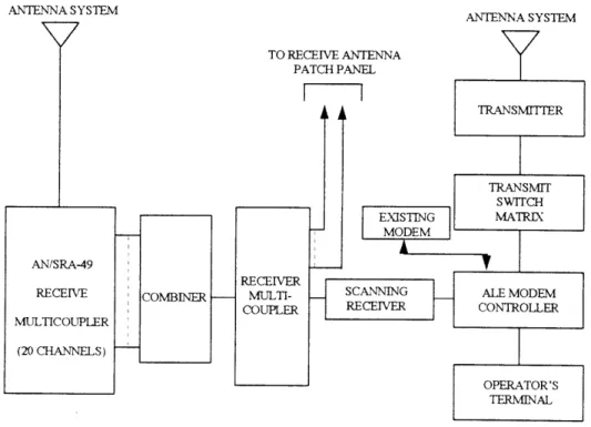
2.4.3.3 Option 3C of Broadband Receiving Subsystem. Option 3 C uses an ALE modem/con-troller supported by a multicoupler such as the AN/SRA-49, dividers, a combiner, a scanning
receiver, and manually tuned transmitters. This configuration is a combination of Options 3A and 3B. In order for an ALE modem/controller to scan the frequency spectrum for an LQA signal, an ALE modem/controller uses a remotely-controllable scanning receiver. An incoming LQA signal is routed through a pre-tuned port in the multicoupler and is split by the divider to go to receivers and the com-biner. The combiner multiplexes all of the incoming signals to a single signal, which is passed on to the scanning receiver where it can monitor all the of pre-selected frequencies from only one port. Upon receipt of an LQA signal, the operator terminal registers an alert of a link attempt for a given frequency. The operator selects a transmitter via the transmit switch matrix and manually tunes the transmitter to the proper frequency to respond to the LQA signal the next time that it cycles around. (Figure 2-7 illustrates Option 3C.)
Figure 2-7. Option 3C broadband receiving subsystem.
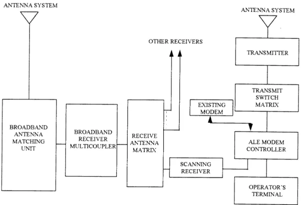
matrix splits the signal to go to the scanning receivers and other receivers. Upon receipt of an LQA signal, the operator terminal registers an alert of a link attempt for a given frequency. The operator is then required to select an available transmitter via the transmit switch matrix and manually tune the transmitter to the proper frequency to respond to the LQA signal the next time that it cycles around. (Figure 2-8 illustrates Option 3D.)
2.4.3.5 Option 3E of Broadband Receiving Subsystem. Option 3E uses an ALE modem/con-troller supported by a multicoupler such as an AN/SRA-49, an RF pre-selector controlled by a scan-ning receiver, and manually tuned transmitters. The AN/SRA-49 combiner provides a broadband sig-nal to the RF pre-selector. The scanning receiver directs the RF pre-selector to tune to the selected frequencies as it searches for LQA handshake signals. Upon receipt of an LQA signal, the operator terminal registers an alert of a link attempt for a given frequency. The operator selects an available transmitter via the transmit switch matrix and manually tunes the transmitter to the frequency to respond to the LQA signal the next time that it cycles around. (Figure 2-9 illustrates Option 3E.)
Figure 2-8. Option 3D broadband receiving subsystem.
Advantages:
S Provides a limited compatible ALE capability for a particular communication circuit. (Options 3A through 3E).
S Scans several frequencies listening for calls (Options 3A through 3E).
S Uses same antennas for ALE and communication service; hence, the use of ALE for frequency guidance to hand-off circuits to other receivers and transmitters can be done with a high degree of reliability for connectivity (Options 3A through 3E).
S Frequency constraint is eliminated when using Option 3D and 3E (Figures 2-7 and 2-8). Disadvantages:
S Number and distribution of frequencies limited by the AN/SRA-49 (for Options 3A, 3B, and 3C).
S Slow response to LQA calls unless transmit subsystem is pre-tuned to the interrogated fre-quency (Options 3A through 3E).
S Potential EMI problems with Option 3D on small platforms.
S Firmware modification may be required for some ALEM/C equipment if the existing modems/
controllers are not designed to operate with a manual tuning transmit subsystem (Options 3A through 3E).
2.4.4 Option 4: Broadband System
This option requires integrating ALE with both a broadband receiving subsystem and a broadband transmitting subsystem. This results in a full broadband system that is unconstrained by any mechani-cally tuned devices. This option is an upgradeable option from Option 3D. (Figure 2-10 shows a typi-cal broadband system configuration.)
Advantages:
S Fully compatible with ALE MIL-STD-188-141A.
S Supports Joint interoperability.
S Upgradeable from Option 3D.
Disadvantages:
S Expensive to do as evolutionary approach for existing ships.
2.5 ALE OPTIONS EVALUATION
Analysis of the four major options discussed results in selecting Options 1, 3D, 3E, and Option 4 for further analysis. Options 2 and 3A/B/C are discarded for the following reasons:
Figure 2-10. Option 3D broadband receiving subsystem.
The system s frequency selection can be determined by using such aids as a Computer Decision Aid (CDA) or pre-coordination with the “master station.” Once tuned to the new frequency, when an LQA handshake is heard, connectivity establishment is fully automatic.
Option 2 cannot support Rule 4 to keep scanning due to the fixed frequency on the port of the mul-ticoupler and on the receiver. It would only have a limited capability with regard to Rules 6 through 9. However, Option 2 is upgradeable to an Option 3 by adding a switch matrix and a scanning receiver capability. But the additional expenditure of time and resources cannot justify the limited capability gained by first going to Option 2. It would be cheaper to go straight to one of the Option 3 configura-tions.
Though this option could support a limited set of services with ALE, it is not cost effective to install this option to achieve such a limited capability that is not upgradeable to a more complete ALE capability without major equipment replacements and costs.
Options 3A/B/C (Broadband Receiving Subsystem) uses a broadband or a broadband-like receive capability to support ALE. Options 3A/B/C are various combinations of equipment (power splitters [dividers], combiners, switches and multicouplers with amplifiers) to providing a limited capability to support narrowband link establishment for one service, while providing LQA information for up to 19 other frequencies when the net is not in use. The use of the AN/SRA-49 receive multicoupler as a pre-selector is the key to the 20 channel receiver scan capability. Hence, these three configurations are limited to the 20 frequencies pre-tuned on the AN/SRA-49 multicoupler, including the frequencies in use and not to be scanned. This is not flexible enough to warrant selection of this option.
configurations, Option 3B-2, a variation of Option 3B that uses a 20 db preamplifier in line between the combiner and the receive multicoupler, provided an acceptable combined noise figure and dynamic range value for narrowband systems.
The trade-off in using one of Options 3A/B/C is that although they can meet the monitoring requirements, these systems still require manually tuning transmitters to the frequency on which the call-up is recognized. Although manually tuned transmitters would meet the technical requirements of the MIL-STD, operationally this may not meet the Commander’s requirements without providing workarounds.
2.5.1 Supporting Rules of Operation
Table 2-1 summarizes the selected options/configurations’ ability to meet the operational require-ments set forth by the Rules of Operations. Option 4 is the only option which will meet the full range of rules stated by MIL-STD-188-141A.
Table 2-1. Operational rules for ALE.
By using a dedicated scanning receiver remotely controllable by the ALE modem/controller, all options/configurations meet the critical requirements for Rule 1. Under Options 1 and 3, if the scan-ning receiver is being used for a circuit, then the receiver may not meet the critical requirements for Rule 2. But if this ALE capability is used to provide frequency guidance to other receivers, then the scanning receiver can “always listen”, satisfying Rule 2.
2.5.2 Meeting Technical Requirements
Table 2-2 reflects the options’ ability to meet the technical requirements necessary for full ALE operation. Again, it is apparent that Option 4 is the only option that meets the full technical
Table 2-2. Technical requirements for ALE.
2.5.3 Capabilities and Benefits
As part of the analysis for cost-effectiveness, it was necessary to evaluate the capabilities and bene-fits gained from each of the options/configurations since each will provide the warfighter with a vary-ing degree of ALE capability. These options were evaluated based on two separate methods of opera-tions: (1) operating as a fully integrated ALE, and (2) operating as a system for providing frequency guidance to other circuits. Table 2-3 summarizes the capabilities and benefits gained by incorporating each option under each method of operation. Again, Option 4 is the only system that provides the full range of capabilities gained by ALE operations. Option 1 could function as an integrated ALE system but could not support other systems. The various systems under Option 3 provided limited capability, and correspondingly, limited benefits.
Table 2-3. Technical requirements for ALE.
2.5.4 Option Limitations
Table 2-4. Limitations of ALE options.
2.6 OPTION TRADE-OFFS
For any given option for the various ALE configurations, there are trade-offs for the capabilities and benefits gained. These trade-offs are in operational capability, technical interoperability, system upgradeability, and fiscal commitment. This section evaluates the four options individually. Because of the limitations of Options 2 and 3A/3B/3C preclude them as viable alternatives for introducing an ALE capability to the Fleet, these options/configurations will not be part of the discussions of option trade-offs.
2.6.1 Option 1 Trade-Offs
Option 1 is the Automatic ALE Transceiver Subsystem, using the ALE capability for supporting one circuit with scanning and monitoring functions. This option represents a typical stand-alone sys-tem in a half-duplex configuration and will not support any communication services requiring full-duplex circuits. As an immediate solution, this option provides the quickest means to a full ALE capability in the Fleet, with both automatic receive and transmit at the least cost.
The trade-off is that this option cannot provide reliable frequency selection to other communica-tions systems/subsystems due to differences in antenna radiation patterns, and would not be upgrade-able to a more complete ALE capability without major equipment replacement and the attendant fis-cal investment costs.
from providing ALE for a high priority service, to monitoring the environment in support of other services, albeit, one at a time.
2.6.2 Option 3 Trade-Offs
Option 3, the ALE Broadband Receiving Subsystem, is a set of configurations that best provide a starting point for evolving ALE into the fleet. All configurations in this option can support a mini-mum fleet introduction capability.
Option 3D meets all ALE receiving criteria with the broadband antenna system and the receiver multicoupler. It provides the best ALE receive capability because it is not limited to the 20 pre-tuned frequencies of the AN/SRA-49. Further, this option is expandable to support broadband transmit capability, making it a viable option IF the funding is identified to upgrade the transmit side to a full broadband system. If the upgrade to a full broadband system is not planned, this option is too costly for such little advantage over the other Option 3 configurations, either technically or operationally.
Option 3E, similar to Option 3D, provides limited capability to support narrowband link establish-ment for one service by using a pre-selector independent of the receiving antenna multicoupler. It is not limited to the 20 pre-tuned frequencies of the multicoupler, since it does not take signal inputs from the AN/SRA-49’s 20 pre-tuned ports. This option does use manually tuned transmitters. How-ever, this option is better than Options 3A/B/C due to a better performance and lower cost for initial investment. From a fiscal perspective, Option 3E provides better performance for a lesser investment cost. It is less costly than Option 3D, but does not provide the broadband upgradeability that Option 3D provides.
There are several possible procedural alternatives to work around the limitations of the manually tuned transmitter in Option 3 and thereby reduce LQA response times. While these alternatives may be useful in assisting the establishment of links with ALE, it will not overcome these limitations. The need for an automated system that is able to achieve a full ALE capability, clearly exists. One alterna-tive would be to use a CDA to predict the best frequency to use. Frequency prediction is based on historical data and modeling computations that may or may not be valid. To provide useful outputs, a CDA must take into consideration antenna radiation patterns as a critical variable in determining usable frequencies for establishing connectivity. Having identified a usable frequency, the operator can pre-tune the transmitter to this frequency. This alternative uses the CDA to identify potential fre-quencies, and positive connectivity has to be tested by either ALE or by the operator. It is still manu-ally intensive, with little advantage gained from having ALE.
Another alternative would be for the OTC to designate a pre-determined frequency on which to set up the transmitters, so when required, the ALEM/C could establish connectivity automatically. How-ever, if the pre-determined frequency or set of frequencies is unusable, the operator would still be forced to find an usable frequency through either experience or through trial and error, and there would have been no significant gain from having ALE onboard.
trans-mitter can be retuned to another “acceptable” frequency and patched to the ALE, which can automati-cally re-establish connectivity on the new frequency when an LQA signal is detected. This assumes that the antenna radiation patterns between platforms are similar enough to provide connectivity.
2.6.3 Option 4 Trade-Offs
Option 4, the ALE Broadband System, is based on the AN/URC-109 and AN/URC-131 design characteristics. These systems are fully MIL-STD-188-141A ALE-compatible when the required ALEM/C and scanning receiver modifications are installed. This option, provides a system that can fully meet all 11 ALE Rules of Operation in MIL-STD-188-141A. This option is the only option that will support all ALE operational requirements for communication services, and is fully compatible with the HF architectural goals recommended in HF 2000 [reference (7)]. It will support intra-/inter-force requirements, ship-to-intra-/inter-forces-ashore requirements, connectivity requirements with U.S. Marines, and with U.S. Air Force AMC aircraft. It is, however, the most expensive option.
2.7 ALE OPTIONS AS POTENTIAL SOLUTIONS
The only option that has been consistent in meeting all ALE requirements, both technical and operational, is Option 4, the ALE Broadband System. This is consistent with the recommendations of HF 2000 [reference (7)], meets all ALE Rules of Operation, and is the recommended ALE option to pursue if cost is not the primary driver. Options are ranked as follows:
1. Option 4, ALE Broadband System, provides the only fully capable and integrated system that is upgradeable for future growth. This option meets all requirements set forth by MIL-STD-188-144A.
2. Option 3E, Broadband Receiving Subsystem, is capable of supporting a limited ALE capability by means of automatic receive and manual transmit tuning.
3. Option 1, Stand-alone ALE Transceiver, is capable of supporting a full ALE capability in the half-duplex mode. It will provide a limited ALE capability if it is used to support multiple cir-cuits.
SECTION THREE
ALE TRANSITION PLAN
3.1 OVERVIEW
This section recommends an HF ALE transition plan that was developed through the process of: 1. Analyzing communications plans and circuit requirements (see Appendix C)
2. Establishing criteria for characteristics to determine if a circuit is suitable for ALE
3. Identifying circuits in typical communications plans which are potential candidates for ALE 4. Analyzing HF communications technologies to develop configuration options (see Appendix
E)
5. Establishing platform implementation priorities based on warfare tasking and command sup-port requirements
6. Reviewing budgetary plans for equipment installation
7. Identifying preferred implementation options that would satisfy operational and technical requirements.
The recommended options were then time-sequenced to execute the most cost-effective transition of HF ALE into the Fleet.
3.2 ALE IMPLEMENTATION PRIORITIES
Affordability dictates phased implementation. Therefore, to aid in ALE implementation and dis-tribution prioritization, the HF communications connectivity requirements of each ship class and their respective priorities for receiving an ALE capability were analyzed. Based on the two communica-tions plans which were examined (see Appendix D) to assess the various services that can take advantage of ALE, it was possible to determine communications requirements for specific ship classes that would require ALE support. From this list, the platforms were evaluated for the relative need for each to receive an ALE capability.
Numbered Fleet Commander flagships were designed with the primary purpose of supporting a Numbered Fleet Commander, and have been upgraded to support Joint/Allied operations with embarked CJTF or Naval Component Commander staffs. Their communications suite configurations support a large number of high priority HF services for Navy/ Joint/Combined/Coalition communica-tions and have the highest priority for receiving HF ALE. They also gain the most benefit from HF ALE.
Battle Force/Battle Group/Amphibious Task Force Commanders also have a strong requirement for HF ALE due to their role in supporting Joint/Allied operations and amphibious/littoral warfare. Flag-ships supporting these commanders have an HF ALE priority similar to the Numbered Fleet Com-mander’s requirements. The same rationale holds true for the flagships that support mid-level com-manders in critical warfare area commander roles, such as the Anti-Air Warfare Comcom-manders (AAWC) embarked on CG-47s. In addition, amphibious ships that play key roles for littoral opera-tions must have a full HF ALE capability for communicaopera-tions with forces on the beach.
capability. For the amphibious ship classes, the requirement for HF ALE reflects the need for com-munications compatibility and operational interoperability with tactical USMC and USA units and their command structure ashore.
The third level of priority is based on requirements for platforms to support the Battle Force/Am-phibious Task Force (BF/ATF). Logistic ship classes meet this criteria, and could conceivably have a higher priority in theaters where the logistics chain is long and logistics coordination over a great dis-tance is required. Others in this level of priority would include DDs, DDGs and supporting Maritime Patrol Aircraft (MPA) that normally would be expected to operate in the force battlespace.
HF ALE Priority 4 is targeted for all other platforms with support roles in the Battle Force, such as the mother ship for MCM/MCH operations, MCM/MCH platforms, and augmentation forces such as FFGs. Table 3-1 summarizes HF ALE Platform Prioritization.
Table 3-1. ALE platform priorities.
3.3 ALE TRANSITION PLAN PROCESS
timeline, ALE equipment is not scheduled for procurement until FY98 (Table 3-2, POM Installation Plan, refers).
For the purposes of this paper, the POM 96 and Transition Plan timelines display radio and ALE equipment installation dates vice procurement or delivery dates to facilitate Battle Group/Amphibious Readiness Group (BG/ARG) composition and capability visualization. POM 96 broadband radio fig-ures are for the AN/URC-131 only. The AN/URC-109 figfig-ures are for units already installed or will be installed shortly, and are all listed as installed by FY95. It should be noted that the POM timeline may not have the HFRG procurement in step with the ALE procurements and does not necessarily take into account BG/ARG composition and deployment schedules. Because of the high degree of capability a broadband system can provide to support ALE, if ALE equipment is procured without HFRG in place, the assets (and funds) cannot be utilized until HFRG is procured and installed. (Ref-erence (11) indicates that ALE will be installed on AN/URC-109-equipped ships before FY98. It is not clear if the funding for this earlier ALE modification is in place of the FY98 funding, or if it is in addition to the FY98 funding profile. If it is additional to the FY98 ALE funding, then alternate units can be ALE configured.) In the Transition Plan timeline, unfunded options appear in parentheses.
BG and ARG compositions were examined for required configurations. BG configurations can be relatively simple or very complex. If BGs are not involved with Joint, Combined, or Coalition opera-tions, the Navy intra-force connectivities is fairly simple. But in a Joint environment, the connectivity requirements become very complex. As a result, carriers should be refitted with full broadband HF ALE. ARGs predominately operate in a Joint environment and therefore require very complex com-munications support. To configure one ARG with a minimum of two broadband capable platforms to function as the interface with USMC units ashore, an AN/URC-131-configured LHA should deploy with an AN/URC-109 configured LHD. Platforms not scheduled to receive broadband systems are proposed to received configurations with a reduced capability that can meet minimal ALE functions, e.g., Option 3E and 1 combination.
The HF ALE Transition Plan timeline was developed for transitioning the Fleet to an HF ALE capability for operational considerations. The HF ALE Transition Plan timeline is based on providing the broadband systems with ALE to the major command platforms (Option 4), and providing the rest of the force with a lower cost, yet affordable ALE configuration (Options 3E and 1) that renders for-cewide ALE capability compliant with MIL-STD-188-141A.
3.3.1 POM ALE Transition Plan
The POM ALE Transition Plan was based on the assumption that all platforms would ultimately be configured with a full broadband HF communications capability, a stated goal of HF 2000. Initially, broadband HF ALE ship classes were identified based on the operational requirement for all com-mand platforms, down through AAWC, to be fully ALE-capable and compatible with all Joint ALE sites, including potential afloat JTF and JFACC platforms. However, the POM 96 funding currently does not satisfy this profile. Procurement and funding shortfalls were identified as follows:
LCC Short one AN/URC-131.
CV/CVN Short one AN/URC-131. Figure is satisfactory if the Training CV is
not scheduled to get HFRG (on the assumption that it will not deploy).
CG-47 Short seven AN/URC-131. This figure is satisfactory as long as the
MLSF Only one AOE-6 class was identified as receiving the AN/URC-131. It is recommended that one third of the MLSF ships should be configured with ALE to meet long range coordination requirements, as found in Pacific and Indian Ocean scenarios. If AN/URC-131s are not going to be procured in sufficient numbers to equipped this many MLSF ships, then they should be included in the Alternative ALE Transition Plan discussed in paragraph 3.2.2 below.
Reviewing the POM, there appears to be sufficient numbers of AN/URC-131 planned for procure-ment to meet the requireprocure-ment for each command ship to be equipped with a system. The installation plan, however, does not ensure that each command ship gets the capability, and does not reflect a requirement for aircraft to receive an ALE capability, such as the MPA P-3s which operate in support of BGs. Table 3-2 reflects the POM FY96 Installation Plan as currently known.
Table 3-2. POM installation plan.
3.3.2 HF ALE Transition Plan
The HF ALE Transition Plan is based on the assumption that although a full, broadband, MIL-STD-188-141A-compliant HF ALE system is the preferred force HF communications architecture, due to budgetary constraints, not all platforms will be configured with a full broadband system. The basis of the HF ALE Transition Plan is to provide the warfighter with an affordable ALE architecture that takes into account operational considerations of how HF is used in the fleet, BG and ARG deployment composition and schedules, and force tactical dispositions, where the desirable situation would be all deploying units have an ALE capability.
(The deficiencies are the same as discussed in paragraph 3.2.1.) This plan assumes that the ALE mod-ifications kits have been installed in the broadband systems. The broadband HFRG implementation with ALE provides the minimum capability necessary to ensure compatibility with all Joint ALE sites, including potential afloat CJTF and Joint Force Air Component Commander (JFACC) plat-forms.
The HF ALE Transition Plan also provides a standard ALE configuration to all nonbroadband plat-forms. These platforms are equipped with a limited ALE capable system (Option 1) and an automatic receive and manual transmit capability (Option 3E) ALE support system. The transceiver (Option 1) replaces transmitters and receivers with their antenna couplers on a one-for-one basis to prevent installing additional antennas to already crowded topside spaces. The Option 3E provides an unlim-ited frequency monitor capability at a very affordable price, to support all HF services. The list of platform classes that would receive this configuration includes CG-47 (Flight I), LPD, LSD, DDG-5 1, DD-963, and Mobile Logistic Support Force (MLSF) ships.
Not shown in Table 3-3 is the reallocation of POM assets that should be made to meet the require-ment for broadband ALE on all major command ships. In order not to increase the procurerequire-ment of AN/URC-131s and the commensurate adverse impact on the budget, a reallocation of POM units is recommended. The three DDG-5 1 and three DD-963 units should be reallocated to remedy the short-fall on the LCC and the CVN. Since the AN/URC-131 configuration differs between platforms, early reallocation is recommended.
It should be noted that the combination of Options 3E and 1 on non-major command platforms will not provide an upgradeable transition path to a full broadband ALE capability with existing technol-ogy. However, focused research and development could rectify this deficiency. The numbers required are noted as deficiencies in Table 3-3 by the number of platforms listed in parentheses (#).
3.4 ALE TRANSITION PLAN
From the options developed by analyzing ship equipment configurations, ALE implementation configurations, ALE standards requirements and operational requirements, and the relative costs of the different options versus the operational gains of each option, it is clear that from an operational perspective the best option is to implement full broadband radios with full ALE implementation on all ships. The transition from today’s narrowband architecture to a full broadband HF radio system with ALE is also the most expensive.
Table 3-3. HF ALE transition plan (modified POM).
If the budgetary environment improves permitting greater broadband procurements, it is recom-mended that the Navy change the procurement profile to include more broadband systems and less of the Option 3E and 1 configurations. This would have minimal operational impact up to FY98 when the first ALE systems are scheduled to be procured. Any such would result in a significant increased capability.
3.5 ALE OPERATIONS
cases, HF is heavily used for tactical communications, with tactical voice services accounting for the largest number of HF circuits.
ALE support is critical to the continuous connectivity of Joint and Combined coordination and command services, and of real-time tactical services that support the various warfare areas. In the Joint/Combined case, the connectivity includes teletype, data and imagery, as well as real-time voice. Real-time tactical services are primarily voice, with future growth in data and imagery areas.
3.5.1 Broad band ALE Operations
The primary emphasis in this area is the connectivities between command entities, especially in a Joint environment, such as between the CJTF, the OTC and the Commander Amphibious Task Force (CATF); between the CATF and Commander Landing Force(CLF); and between CATF/CLF and the OTC of the supporting BGs. At this level, the AN/URC-109 and the AN/URC-131, with ALE modi-fications, are the only systems that can provide the number of circuits to support the number of high priority services that require ALE.
Broadband HF ALE permits greater emphasis on frequency management through the use of quency pools. Frequency pooling permits ALE to select a frequency from a greater number of fre-quencies, thus increasing the probability of finding a workable connectivity. This system also sup-ports ALE frequency monitoring and records the results in a database. The operator can then use the database to select usable frequencies when connectivities are required.
Once frequencies are allocated or pooled, the ALE system is setup to automatically scan the allo-cated frequencies for each circuit. Frequency selection for each circuit can based on using a group call to the participants to “map” the spectrum of assigned frequencies and to select the frequency with the best score for each circuit. Once a database profile has been established for the different circuits, the ALE can used to establish connectivity automatically.
After all the circuits are operating, the master station ALE will continue to transmit LQA calls on frequencies not currently being used to establish a database of scores for each assigned frequency. The other stations will scan the frequencies not being used to detect the LQA calls of the master sta-tion and respond with the appropriate informasta-tion. This will also be entered into their database of scores.
When connectivity is lost on a circuit, the operator is alerted to re-establish connectivity. The oper-ator will direct the ALE to begin LQA call on the appropriate set of frequencies. When a frequency is found that satisfies the ALE LQA score criteria, connectivity may be established with that station or coordination with the master station will be initiated to ensure that all stations can use the frequency. Normally the master station will issue a group call to ensure that all participants can use the fre-quency. If the new frequency is not usable by some units, the master station will continue to transmit LQAs until a usable frequency is found thereby repeating the process.
3.5.2 Non-Broadband ALE Operations
The use of non-broadband systems, such the pre-selector and ALE scanning receiver (Option 3E), and the transceiver with ALE (Option 1) requires a different approach to using ALE. Since neither system will meet the full ALE function set of 11 ALE rules prescribed in MIL-STD-188-141A, the systems must be used in combination to overcome their respective limitations.
i.e., the time between the time connectivity is lost and time it is restored is minimal, even though the transmitters are largely manually tuned. This is accomplished by using a broadband system as the master station to issue sounding calls on all allocated frequencies not currently in use from the pool of frequencies or from the set of frequencies allocated to each circuit. The pre-selector configuration (Option 3E) scans all frequencies in a pool or the set of frequencies allocated to each circuit and records the frequencies on which it hears a sounding LQA call. These frequencies are saved in a data-base. When a service loses connectivity and the operator is alerted, the operator can select from the database another frequency on which the Option 3E system had previously detected a call. A trans-mitter is manually tuned to the new frequency and the next time a call is received on the new fre-quency, the ALE modem/controller responds to the LQA and re-establish the connectivity automati-cally.
A variation of this method would be to have the operator monitor the database and automatically retune a backup transmitter to the best frequency heard. When connectivity is lost, the transmitter would be switched into the ALE configuration to establish the link automatically the next time the ALE modem/controller hears a call on the new frequency. This assumes that there is a spare HF trans-mitter available, and that the connectivity path for that frequency still exists between the two systems.
The transceiver configuration (Option 1) provides a full ALE capability on one service or circuit. This gives the OTC flexible options not previously held. The Option 1 system can be dedicated to support his highest priority circuit, so that when connectivity is lost the operator can initiate ALE to automatically re-establish connectivity on the first frequency it hears a LQA call, or from a set of fre-quencies whose database profile was established using Option 3E configuration and sounding calls. The transceiver option is much faster than the Option 3E configuration because the transmit compo-nent tunes automatically with the receive compocompo-nent, and therefore can respond immediately to LQA calls to establish connectivity. By using the frequency database developed by the Option 3E configu-ration, this assumes that the path is available for the transceivers antenna radiation pattern, which may be different that the Option 3E antenna radiation pattern.
3.6 THE NEXT STEP: ALE CONCEPT OF OPERATIONS
APPENDIX A
ACRONYMS
AAW Anti-Air Warfare
AAWC Anti-Air Warfare Commanders
ADIZ Air Defense Identification Zone
ALE Automatic Link Establishment
ALEM/C Automatic Link Establishment Modem/Controller
AM Amplitude Modulation
AMC Air Mobility Command
AMP Amplifier
AREC Air Resource Element Coordinator
ARG Amphibious Readiness Croup
ASUW Anti-Surface Warfare
ASW Anti-Submarine Warfare
ATF Amphibious Task Force
AUSCANNZUKUS Australia, Canada, New Zealand, United Kingdom, United States
AUTODIN Automated Digital Information Network
BF BattleForce
BG Battle Group
bps bits per second
C & R net Coordination and Reporting Network
C4I Command, Control, Communications, Computers, and Intelligence
CATF Commander Amphibious Task Force
CDA Computer Decision Aid
CJTF Commander Joint Task Force
CLF Commander Landing Force
CMD Command, Commander
CNO Chief of Naval Operations
CONOPS Concept of Operations
COTS Commercial-Off-The-Shelf
CSS Communications Support System
DCS Defense Communications System
DOD Department of Defense
ELOS Extended Line-Of-Sight
EMI Electro-Magnetic Interference
EW Electronic Warfare
FAD Fighter Air Direction
FAX Facsimile
FED-STD Federal Standards
FLTBCST Fleet Broadcast
FLTSAT Fleet Satellite
FY Fiscal Year
HF High Frequency
IMCS Integrated Maritime Communications System
JFACC Joint Force Air Component Commander
JTF Joint Task Force
JTIDS Joint Tactical Information Distribution System
Kbps Kilo-bits-per-second
KHz Kilo-Hertz
km Kilometer
LF Landing Force
LQA Link Quality Analysis
MEU Marine Expeditionary Unit
MHz Mega Hertz
MIL-STD Military Standards
MLSF Mobile Logistics Support Force
MPA Maritime Patrol Aircraft
NATO North Atlantic Treaty Organization
NAVCOMSTA Naval Communications Station
NCCOSC Naval Command and Control Ocean Surveillance Center
NFC Numbered Fleet Commander
NGF Naval Gunfire
NGF S Naval Gunfire Support
NRaD NCCOSC Research and Development Division
NVI Near VerticalIncidence
NVIS Near VerticalIncidence Skywave
OTC Officer in Tactical Command
PARPRO Peacetime Aerial Reconnaissance Program
PIRAZ Primary Identification and Radar Advisory Zone
POM Program Objectives Memorandum
RCVR Receiver
RF Radio Frequency
RPT Report(ing)
SACCS Shipboard Automatic Communications Control System
SAR Search and Rescue
SATCOM Satellite Communication
SEVOX Secure Voice
SI Sensitive Intelligence
SID Sudden Ionosphere Disturbance
SPEC Special, Specification
STANAG Standardization Agreement
STM Serial Tone Modem
TAC Tactical
TADIL Tactical Data Link
TCC Tactical Command Center
TD Technical Document
TTY Teletype
USA United States Army
USAF United States Air Force
USMC United States Marine Corps
VVFD Voice, Video, Facsimile, Data
APPENDIX B
BIBLIOGRAPHY
1. “From the Sea, Preparing the Naval Service for the 21st Century,” Navy and Marine Corps White Paper, September 1992.
2. CINCPACFLT Pearl Harbor HI 2823 10Z OCT 94, NOTAL, Subj: “HIGH FREQUENCY (HF) READINESS AND MODERNIZATION.”
3. COMNAVAIRPAC San Diego CA 020121Z SEP 94, NOTAL, Subj: “HIGH FREQUENCY (HF) READINESS.”
4. Irv Olson & Laird Wallace, “New Tactical Applications of HF Technology Hold Promise for Future Warfighters,” April 1994, AFCEA C4I Symposium
5. Terry A. Danielson, “Professional Notes: Tactical HF Can Get a Whole Lot Better,’’ Naval Insti-tute Proceedings, November 1993, pp 90-92.
6. “Automated High Frequency, High Performance Communications System Onboard USS Tarawa,” NRaD Technical Document 1642, March 1994.
7. “HF 2000 Architecture”, NRaD Draft, August I 994.
8. MIL-STD-188-141A, Interoperability and Performance Standards for Medium and High Fre-quency Radio Equipment, September 15, 1988.
9. “Shipboard Implementation and Concept of Operations for Automatic Link Establishment,” NRaD Technical Document 2575, September 1993.
10. “RF ALE Distribution,” NRaD Document 826-D003-94, September 9, 1994.
11. CNO Washington DC//N6I// 071903Z NOV 94 Subj: “HIGH FREQUENCY (HF) READINESS AND MODERNIZATION.”
APPENDIX C
COMMUNICATIONS PLANS
C.1 COMMUNICATIONS PLANS
Two communications plans were selected to analyze communications requirements, an unclassified version of the Desert Storm Navy communications plan as a representative Joint/Combined/Coalition communications plan, and an Amphibious communications plan from the LHD A specification as a representative plan for amphibious operations.
Both communications plans were examined to determine how HF services were used, how they were used in terms of the criticality of the service to operational units, the requirement for the service to be supported by an HF circuit, and to determine which platforms required HF ALE to meet HF communications requirements. The communications plans used to evaluate requirements in HF 2000 were examined to determine which HF services could and should benefit from use of ALE. First, the two communications plans were examined in the traditional communications plan method, i.e., assigning specific frequencies to support circuits for a given service. Secondly, the communications plans were reviewed again to determine if the service requirements still held true if frequency pools were used to assign frequencies to support a BG. The list of services that could/should benefit from the use of ALE were identical.
APPENDIX D
SHIPBOARD EQUIPMENT
D.1 SHIP EQUIPMENT
HF equipment in the Fleet today was designed to support a circuit-based narrowband HF architec-ture. This architecture, now constrained by the 1950s/60s analog technology available to meet the operational requirements of that time, was designed to provide individual services supported by dedi-cated circuits. Services are defined in terms of the type of information to be exchanged among a com-munity of users (e.g., AAW-related information). Services are identified by a name that generally describes the content or usage of the service, and may include the information exchange format (voice, data, teletype, facsimile, imagery). Circuits are connectivities identified by a circuit identifier, such as A201. Circuits are described by the characteristics that include the assigned frequency, modu-lation characteristics, bandwidth, waveforms, and baud rate. As an example, AAWC C&R is a voice service for coordination and reporting information relating to Anti-Air Warfare. The circuit that sup-ports AAWC C&R may be specified as 4221.5 KHz, 3 KHz bandpass, single sideband, using voice modulated Amplitude Modulation (AM).
In a circuit-based, narrowband architecture, circuits are built by patching narrowband transmitters, receivers, couplers, and antennas together to support the customer’s service. (For the purpose of this document, narrowband is defined as 3 KHz or less instantaneous bandpass.)
As communications technology evolved, some of the operational requirements continued to be sup-ported by the narrowband architecture. For instance, when a secure voice capability became a require-ment, the Navy continued to use narrowband. As such, the existing narrowband architecture is one of the strongest driving forces in the manner in which resources are allocated and used in communica-tions.
HF technology is rapidly advancing to provide greater bandwidth and greater throughput. Simulta-neously, communications is moving toward a digital, service-based architecture, with greater com-puter control and only manual override. HF is becoming the backbone of Extended Line-Of-Sight (ELOS) intra-force RF networking.
This appendix will summarize the existing and new HF equipment configurations by ship class where communications suites are standard or variations of the basic configuration. These configura-tions are used in Section Three to determine the platform’s capability to support the different ALE configurations identified in Section Two.
D.2 EXISTING SHIP EQUIPMENT
The existing HF communications suites in the Fleet are primarily narrowband systems with manu-ally tuned receivers, transmitters and couplers. Figure D-1 is representative of a narrowband HF sys-tem currently installed in the fleet and illustrates the various components by their functional name.
Figure D-1. Generic narrowband HF system.
D.2.1 Standard Narrowband HF Configuration
The standard narrowband HF configuration is a collection of narrowband equipments patched together to meet circuit configuration requirements:
AN/URT-23 Transmitters R-1051 Receivers
AN/SRA-56/57/58 Transmitter Multicouplers AN/SRA-49 Receiver Multicoupler
AN/URA-3 8 Transmitter Antenna Coupler CU-2 113 CARTS for Receivers
Manual RF Switching Matrices
This baseline configuration, with minor variations, is reflected in the following ship classes: S CG-47 class (Flight II, e.g. CG-54 and newer):
R-2368/URR-79 Receivers (replaces R-1051)
S DDG-51 class:
R-2368/URR-79 Receivers (replaces R-1051)
(The AN/URA-38 Transmitter Antenna Coupler was deleted.)
S FFG-7 class:
R-2368/URR-79 Receivers (replaces R-1051)
(The AN/URA-38 Transmitter Antenna Coupler was deleted.)
D.2.2 Modified Standard Narrowband HF Configuration