FACULTY OF ELECTRICAL ENGINEERING
A NEW GENETIC ALGORITHM
BASED SCHEDULING
ALGORITHM FOR THE LTE
UPLINK
SAULO HENRIQUE DA MATA
A NEW GENETIC ALGORITHM BASED SCHEDULING
ALGORITHM FOR THE LTE UPLINK
Thesis s u b m it t e d in p a r t ia l f u l f il l m e n t o f t h e r e q u ir e m e n t s
FOR THE DEGREE OF DOCTOR OF SCIENCES TO THE POST-GRADUATE Pr o g r a m o f t h e Fa c u l t y o f El e c t r ic a l En g in e e r in g a t th e
Fe d e r a l Un iv e r s it y o f Ub e r l â n d ia.
Me m b e r s o f t h e Co m m it t e e:
Pr o f. Dr. Pa u l o Ro b e r t o Gu a r d ie ir o ( Ad v is o r) - UFU
Pr o f a. Dr a. Ju l ia n a Fr e it a g Bo r in - UNICAMP
Pr o f. Dr. Má r c io An d r e y Te ix e ir a - IFSP
Pr o f. Dr. Éd e r s o n Ro s a d a Silva - UFU
Pr o f. Dr. Má r c io Jo sé d a Cu n h a - UFU
M425n
2017 Mata, Saulo Henrique da, 1986-A new genetic algorithm based scheduling algorithm for the LTE Uplink / Saulo Henrique da Mata. - 2017.
120 f : il.
Orientador: Paulo Roberto Guardieiro.
Tese (doutorado) - Universidade Federal de Uberlândia, Programa de Pós-Graduação em Engenharia Elétrica.
Inclui bibliografia.
1. Engenharia elétrica - Teses. 2. Long-Term Evolution (Telecomunicações) - Teses. 3. Algoritmos genéticos - Teses. I. Guardieiro, Paulo Roberto, 1952- II. Universidade Federal de Uberlândia. Programa de Pós-Graduação em Engenharia Elétrica. III. Título.
A N E W GENETIC ALGORITHM BASED SCHEDULING ALGORITHM FOR THE LTE UPLINK
Thesis submitted in partial fulfillment of the requirements for the degree of Doctor of Sciences to the Post-Graduate Program of the Faculty of Electrical Engineering at the Federal University of Uberlândia.
Prof. Paulo Roberto Guardieiro, Dr. Advisor
Prof. Alexandre Cardoso, Dr.
Acknowledgments
Firstly, I would like to thank God, that was with me in each day of work. Thank You for the perseverance, patience and health, that were present during this journey.
To prof. Dr. Paulo Roberto Guardieiro for the always dedicated and patient guid ance. Thank you for the encouragement and for teaching me not only technical concepts, but also for being an example of conduct and professionalism.
To my family, for the support at all times. I thank my mother Domingas, my father José and my fiancée Joyce for their support in difficult times, for understanding my absence in so many moments and for the trust placed in me.
Thanks to my friends for the company, support, learning, and so many moments of relaxation and joy.
Finally, I thank FAPEMIG (Fundação de Amparo à Pesquisa de Minas Gerais) for the financial assistance to make this work viable.
Abstract
da Mata, S. H., A NEW GENETIC ALGORITHM BASED SCHEDULING ALGO RITHM FOR THE LTE UPLINK , UFU, Uberlândia, Brazil, 2017, 102p.
Long Term Evolution has become the de facto technology for the 4G networks. It aims to deliver unprecedented data transmission rates and low latency for several types of applications and services. In this context, this thesis investigates the resource allo cation in the LTE uplink. From the principle that resource allocation in the uplink is a complex optimization problem, the main contribution of this thesis is a novel scheduling algorithm based on Genetic Algorithms (GA). This algorithm introduces new operations of initialization, crossover, mutation and a QoS-aware fitness function. The algorithm is evaluated in a mixed traffic environment and its performance is compared with relevant algorithms from the literature. Simulations were carried out in ns-3 and the results show that the proposed algorithm is able to meet the Quality of Service (QoS) requirements of the applications, while presenting a satisfactory execution time.
Index-terms: LTE, Uplink, Scheduling Algorithms, Genetic Algorithms, ns-3
Contents
List of Figures ix
List of Tables xi
List of Abbreviations xii
1 Introduction 1
1.1 Problem Definition... 2
1.2 State of the A r t... 3
1.3 Justification... 5
1.4 Research Scope and O bjectives... 6
1.5 Novelty and Contributions... 7
1.6 The Structure of the T h esis... 8
2 The Long-Term Evolution Network 9 2.1 Historical Context of the Mobile Networks... 9
2.1.1 First-Generation Mobile Networks ( 1 G ) ... 9
2.1.2 Second-Generation Mobile Networks ( 2 G ) ... 10
2.1.3 Third-Generation Mobile Networks (3 G )... 11
2.1.4 Fourth-Generation Mobile Networks ( 4 G ) ... 12
2.1.5 Fifth-Generation Mobile Networks ( 5 G ) ... 16
2.2 Network Architecture ... 18
2.2.1 User Equipment ... 18
2.2.2 E-UTRAN ... 19
2.2.3 Evolved Packet C o re ... 20
2.3 Protocol Architecture ... 21
2.3.1 User Plane Protocols... 21
2.3.2 Control Plane P rotocols... 22
2.4 Logical, Transport and Physical Channels... 23
2.4.1 Logical Channels... 23
2.4.3 Physical C hannels... 2.5 Sum m ary...
3 Resource Allocation in the LTE Network
3.1 Physical Layer D e s ig n ... 3.1.1 OFDM A... 3.1.2 SC-FDMA ... 3.2 Cyclic Prefix ... 3.3 The Resource Grid Structure... 3.4 Bandwidth ... 3.5 Link A daptation ... 3.6 H A R Q ... 3.7 Buffer Status R ep ort... 3.8 Power Headroom R eport... 3.9 Quality of Service M echanism s... 3.10 Sum m ary...
4 LTE Uplink Packet Scheduling
4.1 Packet Scheduler... 4.2 Utility Functions... 4.2.1 Maximum Throughput ( M T ) ... 4.2.2 Proportional Fairness (PF) ... 4.3 Round Robin (R R )... 4.4 Riding Peaks ( R P ) ... 4.5 Recursive Maximum Expansion (RME) ... 4.6 Riding Peaks with QoS (R P Q oS )... 4.7 Sum m ary...
5 A New Three-Step GA-Based Scheduling Algorithm for the LTE Up link
5.1 Genetic Algorithms... 5.2 Three-Step GA-Based Scheduling Algorithm... 5.2.1 Step O n e ... 5.2.2 Step T w o ... 5.2.3 Step T h r e e ... 5.3 Sum m ary...
6 Performance Evaluation
6.1 Simulation Environment...
6.3 Simulation R esu lts... 80
6.3.1 Throughput... 80
6.3.2 Packet D e la y ... 84
6.3.3 Packet Loss Ratio ... 85
6.3.4 Throughput Fairness I n d e x ... 87
6.3.5 P S N R ... 89
6.3.6 Algorithm Complexity... 93
6.4 Sum m ary... 94
7 Conclusions 95
References 98
2.1 Global data traffic in mobile networks... 13
2.2 Convergence of wireless technologies... 14
2.3 LTE releases... 15
2.4 1MT-2020 capabilities... 17
2.5 The EPS network elements... 19
2.6 User plane protocol stacks... 21
2.7 Control plane protocol stacks... 22
2.8 Air interface protocol stack... 24
3.1 OFDMA subcarrier spacing... 28
3.2 Block Diagram of the OFDMA transmitter... 29
3.3 Block Diagram of the SC-FDMA transmitter... 30
3.4 Comparison of OFDMA and SC-FDMA transmitting a series of QPSK data symbols... 31
3.5 Operation of cyclic prefix insertion... 32
3.6 Organization of symbols into slots using the normal and extended cyclic prefixes... 33
3.7 Frame structure type 1, used in FDD mode... 33
3.8 LTE resource grid... 34
3.9 The overall EPS bearer service architecture... 39
3.10 Downlink GTP tunneling... 41
4.1 Riding Peaks... 48
4.2 Recursive Maximum Expansion... 50
5.1 TSGA overview... 57
5.2 GA flowchart: how it works... 60
5.3 Binary matrix representation... 61
5.4 Vector representation... 62
5.5 HARQ impact on the metric matrix... 63
5.7 Crossover operation... 68
5.8 Crossover operation considering discontinuities and fake users... 69
5.9 Mutation operation... 69
5.10 Mutation operation considering discontinuities... 70
6.1 ns-3 software organization... 75
6.2 Simulation topology... 75
6.3 Deployment area... 77
6.4 MCS: average and CDF values... 77
6.5 Aggregated cell throughput... 81
6.6 Aggregated cell throughput for users running the Video application. . . 82
6.7 CDF of throughput for users running the FTP application, considering 200 users in the cell... 83
6.8 CDF of throughput for users running the Video application, considering 200 users in the cell... 83
6.9 Average delay for users running the FTP application... 84
6.10 Average delay for users running the Video application... 85
6.11 Average delay for users running the VoIP application... 85
6.12 Average PLR for users running the FTP application... 86
6.13 Average PLR for users running the Video application... 87
6.14 Average PLR for users running the VoIP application... 87
6.15 Inter-class fairness index... 88
6.16 Intra-class fairness index for users running the FTP application... 89
6.17 Intra-class fairness index for users running the Video application... 90
6.18 Intra-class fairness index for users running the VoIP application... 90
6.19 PSNR for users running the Video application... 91
6.20 Comparison of the average video quality provided by each scheduling algorithm under evaluation, considering 50 video application users in the cell... 92
6.21 Average execution time for simulations... 94
2.1 LTE logical channels... 23
2.2 LTE transport channels... 25
2.3 LTE physical channels... 25
2.4 LTE control information... 26
3.1 LTE supported bandwidths... 34
3.2 Standardized QoS Class Identifiers (QCIs) for LTE... 40
4.1 Metric matrix... 45
4.2 Notation used for scheduling metrics... 46
4.3 Pseudocode notation and nomenclature... 47
6.1 Traffic Sources... 78
6.2 EvalVid Simulation Parameters... 79
6.3 Simulation Parameters... 80
16-QAM 16-Quadrature Amplitude Modulation
1G First-Generation Mobile Networks
2G Second-Generation Mobile Networks
3G Third-Generation Mobile Networks
3GPP Third Generation Partnership Project
3GPP2 Third Generation Partnership Project 2
4G Fourth-Generation Mobile Networks
64-QAM 64-Quadrature Amplitude Modulation
AMBR Aggregate Maximum Bit Rate
AMC Adaptive Modulation and Coding
AMPS Analogue Mobile Phone System
ARP Allocation and Retention Priority
AS Access Stratum
ATB Adaptive Transmission Bandwidth
BCCH Broadcast Control Channel
BCH Broadcast Channel
BLER Block Error Rate
BSR Buffer Status Report
CA Carrier Aggregation
CAC Call Admission Control
CCI Co-Channel Interference
CDF Cumulative Distribution Function
CDMA Code Division Multiple Access
CFI Control Format Indicator
CoMP Coordinated Multi-Point
CQI Channel Quality Indicator
CSI Channel State Information
CTTC Centre Tecnologic de Telecomunicacions de Catalunya
DCCH Dedicated Control Channel
DCI Downlink Control Information
DFTS-OFDMA Discret Fourier Transform Spread Orthogonal Frequency Division Mul tiple Access
DL-SCH Downlink Shared Channel
DTCH Dedicated Traffic Channel
E-UTRAN Evolved UMTS Terrestrial Radio Access Network
EDGE Enhanced Data Rates for GSM Evolution
EMM EPS Mobility Management
eNB evolved NodeB
EPA Extended Pedestrian A
EPC Evolved Packet Core
EPS Evolved Packet System
ESM EPS Session Management
ETSI European Telecommunications Standards Institute
EV-DO Evolution Data Optimized
EVA Extended Vehicular A
FDPS Frequency Domain Packet Scheduling
FEC Forward Error Correction
FFT Fast Fourier Transform
FME First Maximum Expansion
FTP File Transfer Protocol
GA Genetic Algorithms
GBR Guaranteed Bit Rate
GPRS General Packet Radio Service
GSM Global System for Mobile Communication
GTP-U GPRS Tunneling Protocol User Part
GUI Graphical User Interface
HARQ Hybrid Automatic Repeat Request
HI Hybrid ARQ Indicator
HRPD High Rate Packet Data
HSDPA High Speed Downlink Packet Access
HSPA High Speed Packet Access
HSS Home Subscriber Server
HSUPA High Speed Uplink Packet Access
IMT-2000 International Mobile Telecommunications-2000
IMT-2020 International Mobile Telecommunications-2020
IMT-Advanced International Mobile Telecommunications-Advanced
IP Internet Protocol
ISI Inter Symbol Interference
ITU International Telecommunication Union
ITU-R International Telecommunication Union Radiocommunication Sector
LA Link Adaptation
LENA LTE-EPC Network simulAtor
LTE Long-Term Evolution
MAC Medium Access Control
MADE Minimum Area-Difference to the Envelope
MBMS Multimedia Broadcast/Multicast Service
MBR Maximum Bit Rate
MCH Multicast Channel
MCS Modulation Coding Scheme
MIMO Multiple Input Multiple Output
MME Mobility Management Entity
MT Maximum Throughput
MT Mobile Termination
MTC Machine-Type Communication
NAS Non Access Stratum
NMT Nordic Mobile Telephone System
Non-GBR Non-Guaranteed Bit-Rate
ns-3 Network Simulator 3
OFDMA Orthogonal Frequency Division Multiple Access
P-GW PDN Gateway
PAPR Peak-to-Average Power Ratio
PBCH Physical Broadcast Channel
PCCH Paging Control Channel
PCFICH Physical Control Format Indicator Channel
PCH Paging Channel
PDCP Packet Data Convergence Protocol
PDN Packet Data Network
PDSCH Physical Downlink Shared Channel
PDU Protocol Data Unit
PF Proportional Fairness
PHICH Physical Hybrid ARQ Indicator Channel
PHR Power Headroom Report
PLR Packet Loss Ratio
PMCH Physical Multicast Channel
PMI Pre-coding Matrix Indicators
PRACH Physical Random Access Channel
PS Packet Scheduler
PSNR Peak Signal-to-Noise Ratio
PUCCH Physical Uplink Control Channel
PUSCH Physical Uplink Shared Channel
QCI QoS Class Identifier
QoS Quality of Service
QPSK Quadrature Phase Shift Keying
RA Resource Allocation
RACH Random Access Channel
RB Resource Block
RBG Radio Bearer Group
RI Rank Indications
RLC Radio Link Control
RME Recursive Maximum Expansion
RR Round Robin
RRC Radio Resource Protocol
RRM Radio Resource Management
S-GW Serving Gateway
Sl-AP SI Application Protocol
SAE System Architecture Evolution
SAW Stop-And-Wait
SC-FDMA Single Carrier Frequency Division Multiple Access
SCTP Stream Control Transmission Protocol
SIC Successive Interference Cancellation
SINR Signal to Interference plus Noise Ratio
SMS Short Message Service
SNR Signal to Noise Ratio
SR Scheduling Requests
SRS Sounding Reference Signals
TACS Total Access Communications System
TB Transport Block
TCP Transmission Control Protocol
TDD Time Division Duplexing
TDMA Time Division Multiple Access
TDPS Time Domain Packet Scheduling
TE Terminal Equipment
TEID Tunnel Endpoint Identifier
TFT Traffic Flow Template
TTI Transmission Time Interval
UDP User Datagram Protocol
UE User Equipment
UICC Universal Integrated Circuit Card
UL-SCH Uplink Shared Channel
UMTS Universal Mobile Telecommunication System
USIM Universal Subscriber Identity Module
UTRAN UMTS Terrestrial Radio Access Network
VoIP Voice over IP
WCDMA Wideband Code Division Multiple Access
- Immanuel Kant
1
Introduction
In t h e p a s t y e a r s, we have been witnessing a tremendous growth of mobile networks
subscribers. This fact has demanded a continuous evolution of the current mobile networks, to attend the always crescent expectations of these users. Applications, such as Voice over IP (VoIP), web browsing, video chat and video streaming, have applied new challenges to the design of mobile networks, because of their delay and bandwidth strict requirements.
In this context, the Long-Term Evolution (LTE) network has emerged as one of the most promising solutions to overcome these new challenges. LTE is a packet-based mobile broadband network. It has been developed by the Third Generation Partnership Project (3GPP) and aims to deliver high throughput, low latency and an enhanced spectral efficiency with respect to previous 3G networks [1].
In this sense, the resource allocation mechanism is a key feature of the LTE network. However, the plurality of applications and different QoS requirements bring to light complex challenges to resource allocation design.
In the next sections, we identify these main challenges, and what have been devel oped by the community of researchers. This will allow us to build a map to guide our efforts in the proposal of a new scheduling algorithm for the LTE network.
1.1 Problem Definition
In the LTE system, the User Equipment (UE) gets access to the network through the base station, which is known as evolved NodeB (eNodeB or eNB). The eNodeB is responsible for the allocation of the network resources among the UEs attached to it.
In a real propagation environment, the air interface is characterized by fast fading variations, resulting from the multiple possible paths that the signal can travel until it reaches the receiver. Depending on the path, it can occur a constructive or a destructive recombination of the signal at the receiver. The position and distance of the receiver from the transmitter also influence these fast fading variations. Moreover, high data rate transmission in a multipath environment leads to Inter Symbol Interference (ISI) and, consequently, bit errors at the receiver [2].
From the previous 3GPP mobile networks, one of the most important changes in troduced by LTE is the shift from the use of Code Division Multiple Access (CDMA) to Orthogonal Frequency Division Multiple Access (OFDMA) [3]. OFDMA simplifies the design of channel equalizers and it is a powerful way to solve the ISI problem. Further more, OFDMA offers high spectral efficiency, scalability and flexibility of bandwidth allocation, since the resource allocation can occur in time and frequency domains.
Despite the great advantages of OFDMA, it also presents some issues. The main one is the high Peak-to-Average Power Ratio (PAPR). This means that the power of the transmitted signal is subject to rather large variations, which cause the amplifiers to reach saturation region, resulting in a non-linear distortion. In the downlink, the eNodeB transmitters are large, expensive devices, so they can avoid this problem by using expensive power amplifiers that are very close to linear. In the uplink, a UE transmitter has to be cheap and present reduced power consumption [2].
offers reduced power consumption and improved coverage. On the other hand, it requires the subcarriers allocated to a single UE to be adjacent [4]. Therefore, the scheduler for the uplink has limited degrees of freedom: it has to allocate contiguous Resource Blocks (RBs) to each user without the possibility of choice among the best available ones [1]. This constraint will prove to be very challenging when designing scheduling algorithms [4], since the incorporation of the RB contiguity constraint into the uplink scheduling algorithms was proven to be NP-hard [5], i.e., it is impractical to perform an exhaustive search.
Downlink and uplink have a radio link with a time variant nature, due to the fast fading phenomenon, as said before. Thus, the eNodeB must consider the UEs current quality of channel to allocate the resources in an effective manner. In the downlink, the quality of the channel is obtained through the Channel Quality Indicator (CQI), which is reported by the UE to the eNodeB. For the uplink, the eNodeB estimates the channel’s quality using channel sounding techniques. From the channel’s quality, the system can perform link adaptation using Adaptive Modulation and Coding (AMC) techniques, i.e. the system can choose a more robust Modulation Coding Scheme (MCS) under adverse channel conditions to improve spectral efficiency.
In this sense, channel-aware solutions are usually adopted in LTE resource alloca tion, since they are able to exploit channel quality variations by assigning higher priority to users experiencing better channel conditions. However, the channel quality cannot be the only factor in the resource scheduling process. The scheduling algorithm must also take into consideration, for example, the average throughput of the cell, fairness index and mainly the QoS requirements.
Finally, one can see that the design of a scheduling algorithm for the LTE network is a complex task. There are many issues to be addressed in order to obtain a high spectral efficiency and to meet the QoS requirements. Thus, a powerful and effective scheduling algorithm should be channel-aware/QoS-aware. The uplink channel is even more chal lenging, since the SC-FDMA requires that the subcarriers allocated to a particular UE must be adjacent, elevating the complexity to NP-hard level [5].
In the next section, the most relevant works that propose solutions for the above issues are presented.
1.2 State of the Art
the key features for the downlink packet scheduler design and present a survey with the main papers about this issue.
The uplink channel has received less attention, but one can find interesting papers dealing with the uplink scheduling challenges, as listed in [6]. In [7], we can find one of the first proposals to solve the problem of the localization constraint for RB assignment. It is based on an earlier work [8], which suggests assigning RBs to users who obtain the highest marginal utility.
Calabrese et al. [9] propose a search-tree algorithm, assuming the resources equally shared among users. Further, Calabrese also proposed in [10] an Adaptive Transmission Bandwidth (ATB) algorithm. According to the authors, the main advantage provided by ATB scheduling algorithm is more flexibility to accommodate the varying cell load, when compared to the search-tree algorithm.
Temino et al. [11] propose three new scheduling algorithms: the First Maximum Expansion (FME), the Recursive Maximum Expansion (RME) and the Minimum Area- Difference to the Envelope (M ADE). According to authors, RME outperforms FME. M AD E presents a small gain over RME in some scenarios, but with a much greater computational complexity.
In another contribution [5], Lee et al. propose four scheduling algorithms. Among them, we highlight the Riding Peaks (RP) algorithm. It is based on the fact that in multi-carrier systems, the channel state of a user is correlated in both time and frequency. Thus, it tries to use each user’s highest valued RBs as much as possible. This algorithm is simple and performs quite well, but according to the authors it leads to bad solutions if the channel presents abrupt changes of the Signal to Noise Ratio
(SNR) from one RB to the next.
Safa et al. [12] performe a comparison of three scheduling algorithms: RME, FME and RP. Despite of the issues indicated in [5], according to Safa, the RP algorithm presented better performance than the other two algorithms under evaluation.
In [13], Kaddour et al. also present a comparison of RP, RME and their own proposed algorithm in the context of a power efficient resource allocation. As expected, RP and RME did not perform well in these scenarios, since they do not consider the transmission power in the resource allocation.
considering VoIP, video streaming and FTP applications. The authors highlight the challenges to provide a fair evaluation environment for comparing the schedulers pro posed for the uplink. They also affirm that the schedulers under evaluation performed almost similarly.
From the algorithms presented in [5], [9] and [11], we can find a set of works that tried to improve these three solutions and add QoS capabilities, by giving different priorities to the traffics from the utility function, as in [15], [16] and [17]. In [15], Safa et al. present an interesting scheduler that will be described in Chapter 4 and used in the performance evaluation in Chapter 6.
As stated in Section 1.1, finding the optimal solution to the LTE uplink scheduling is a NP-hard problem. In this sense, greedy heuristic algorithms can find ’’good enough” solutions, performing a trade-off between computational performance and accuracy. At their worst case, they might not perform well, but in practice, their overall performance is very good [12]. On the other hand, there are tools that were designed to deal with NP-hard problems. One of the most known is the Genetic Algorithms (GA). GA is capable of delivering near-optimal performance with comparatively low complexity [18].
GA has been used in scheduling algorithms mainly for the downlink, as in [3] - [20]. For the uplink, one can find a set of works dealing with mitigation of Co-Channel Inter ference (CCI) using Successive Interference Cancellation (SIC) as described in [21] and
[22]. These works are more related to Coordinated Multi-Point (CoMP) transmission and multi user scheduling. It does not consider the NP-hard issue of the localization constraint for the RB assignment.
In [23], Kalil et al. also employ GA in the LTE uplink scheduling and they considered the RB contiguity constraint. However, the proposed algorithm is compared only with the optimal solution, and the authors used a simple scenario with a small number of users and there is not any information about the traffic in the cell.
1.3 Justification
Based on what was presented in the previous sections, one can see that the resource allocation in LTE uplink is a complex task, rated as NP-hard. Despite the availability of tools to solve this kind of problem, like the Genetic Algorithms, to the best of our knowledge, there are few studies about the use of GA as the heuristic of an LTE uplink scheduling algorithm, regarding the contiguity RB constraint.
also into account the several already existent uplink scheduling algorithms based on traditional techniques, we believe that there is a great opportunity of research in the design of an LTE uplink scheduling based on the Genetic Algorithms.
1.4 Research Scope and Objectives
The main objective of this work is to solve the resource allocation problem in the LTE uplink. In order to achieve this goal, we considered the complexity of this optimization problem and chose the Genetic Algorithms as the strategy of scheduling.
GA is powerful tool to solve complex optimization problems and has not been fully studied in this context yet. In this sense, a second objective of this work is to verify if GA can be applied in the LTE uplink resource allocation and how it performs compared to the literature solutions. Due to restrictions of the simulation tool, this thesis will focus on the Release 8 of the LTE standard. When suitable, we point out the impact of features of newer releases in the proposal described in this thesis. The optimization of the GA parameters are not in the scope of this thesis. On the other hand, the pro posed algorithm should be able to meet the QoS requirements of different applications, considering the contiguity constraint for RB assignment, while presenting a satisfactory execution time.
To evaluate the proposed scheduling algorithm it is necessary to define a simulation environment, since there are a substantial number of parameters involved, resulting into an very complex analytical approach, and a real testbed would be very expensive. From the papers mentioned in Section 1.2, one can see that most of the authors use their own implementation of simulator or commercial/private simulators. In summary, these simulation environments are neither publicly available nor complete nor easy to use. This brings a huge challenge for researchers interested in studying and comparing their works with the state of art solutions. This fact was highlighted by the authors of [14].
1.5 Novelty and Contributions
The main contribution of this thesis is a novel scheduling algorithm based on Genetic Algorithms for the LTE uplink networks.
From the scheduling algorithms listed in Section 1.2, the only one that is really close to our proposal is the one described in [23]. The closeness can be noted in the strategy to solve the resource allocation problem, i.e., both schedulers use Genetic Algorithms to allocate resources in the uplink channel, considering the contiguity constraint. However, representation, initialization, crossover, mutation and evaluation are distinct in the two proposals. When compared to [23], our proposal presents the following improvements:
• the algorithms are evaluated using three traffic models for FTP, VoIP and Video Chat applications, while the evaluation in [23] presents only one traffic;
• our proposal presents a new three-step strategy of allocation. We believe that this three-step approach is the main element responsible for making our algorithm competitive in execution time. In [23], there is not a complexity analysis;
• our algorithm presents a novel QoS-aware fitness function. The fitness function in [23] is not QoS-aware;
• our scheduler employs a packet discarding strategy to meet the packet delay budget of the applications;
• our evaluation presents a fairer, challenger and more realistic comparison, since we added a QoS-aware algorithm in the evaluation to compete with our proposal.
Furthermore, the scheduling algorithm presented in this thesis, introduces new strategies of initialization, crossover and mutation that complies with the contiguity constraint for the RBs assignment.
To the best of our knowledge, there is not any previous work that proposes such a robust GA-based scheduler and presents a complete evaluation, considering several network performance indicators.
It is also worth saying that to evaluate the proposed algorithm, we had to implement new scheduling algorithms and traffic generators in ns-3 [24]. These implementations can help other researchers in their evaluations.
Finally, we would like to highlight that the novelty and contributions of the research presented in this thesis were corroborated and accepted by the community of researchers, by means of the following publications:
• S. H. da Mata, P. R. Guardieiro, Resource allocation for the LTE uplink based on Genetic Algorithms in mixed traffic environments, Computer Communications 107 (2017) 125-137. doi:10.1016/j.comcom.2017.04.004.
• J. M. H. Magalhães, S. H. da Mata, P. R. Guardieiro, Downlink and Uplink Resource Allocation in LTE Networks, in: Handbook of Research on Next Gen eration Mobile Communication Systems, IGI Global, 2015, pp. 199-233. doi: 10.4018/978-l-4666-8732-5.ch009.
• S. H. da Mata, P. R. Guardieiro, A Genetic Algorithm Based Approach for Re source Allocation in LTE Uplink, in: 2014 International Telecommunications Sym posium (ITS), 2014, pp. 1-5. doi:10.1109/ITS.2014.6947956.
1.6 The Structure of the Thesis
This thesis is organized as follows.
Chapter 2 is dedicated to the introduction of the main concepts of the LTE network that are important to understand the research described in this thesis.
In Chapter 3, we give more details of the resource allocation process in the LTE system. This chapter describes how the LTE resources are organized to be shared among the users.
Chapter 4 is dedicated to present the packet scheduler. In this chapter, we introduce the main requirements and functionalities of the packet scheduler and present the most relevant scheduling algorithms found in the literature.
In Chapter 5, we describe the proposed algorithm. This chapter introduces the Genetic Algorithms and how this technique is used to solve the LTE uplink scheduling issues.
In Chapter 6, we evaluate the proposed algorithm. This chapter also describes the simulation environment used to perform the evaluation and it presents the results of the evaluation as well.
- Albert Einstein
2
The Long-Term Evolution Network
The Lo n g- Te r m Ev o l u t io n is a very complex network with many elements that
make use of several concepts and technologies. This chapter presents some of these elements and concepts that are important to facilitate the understanding of the research delineated in this thesis.
2.1 Historical Context of the Mobile Networks
LTE is commonly known as a mobile network of fourth generation (4G) [2]. In this sense, there is a logical thought about what previous mobile networks technologies formed the past generations. In this section, we have a brief discussion about the evolution of mobile networks.
2.1.1 First-Generation Mobile Networks (1G)
• The Analogue Mobile Phone System (AMPS), used in the USA.
• The Nordic Mobile Telephone System (NMT) and the Total Access Communica tions System (TACS), used in Europe.
• The Japanese Total Access Communication System (J-TACS), used in Japan and Hong Kong.
All these systems were based on analogue communication technologies and limited only to voice services [26]. Despite the good voice quality, these systems presented a limited spectral efficiency. Besides, the mobile devices were large and expensive. These problems motivated the development of a new mobile network.
2.1.2 Second-Generation Mobile Networks (2G)
In the early 1990s, the digital communications were already mature enough to support commercial systems. In this context, a Second-Generation of mobile networks were developed based on digital technology, which permitted a better spectral efficiency, associated with smaller and cheaper devices [2].
Initially, these systems were developed to support only voice services. However, later, they were enhanced to support circuit-switched data services. One of these first services was the Short Message Service (SMS) [27].
The most popular 2G system is the Global System for Mobile Communication (GSM), designed by a set of companies working together under the guidance of the European Telecommunications Standards Institute (ETSI). GSM uses Time Division Multiple Access (TDMA) as the transmission method.
Another notable standard is IS-95, also known as cdmaOne, designed by Qualcomm and used in the USA. This system is based on Code Division Multiple Access (CDMA).
The small and long battery life terminals of 2G networks helped to spread these tech nologies worldwide. Simultaneously, Internet was presenting a very promising growth. This context promoted the junction of these two concepts: Internet data services offered in a mobile device. To achieve this goal, network operators developed enhancements in the original 2G networks. These enhanced systems are often referred as 2.5G mobile networks [27]. The main improvements were the introduction of a packet-switched core network and a modified air interface to handle voice and data transmission.
[26]. Further enhancements were integrated to the GSM network with the introduc tion of the Enhanced Data Rates for GSM Evolution (EDGE) technique. EDGE has increased data rates up to 384 Kbps [26].
2.1.3 Third-Generation Mobile Networks (3G)
In 1997, the International Telecommunication Union (ITU) published the Recommen dation ITU-R M.687-2 entitled International Mobile Telecommunications-2000 (IMT- 2000) [28]. This recommendation was launched as an initiative to promote high quality mobile multimedia networks, which can offer high speed broadband, Internet Protocol
(IP) based system and global roaming, among other features.
From this initiative, two partnership organizations were born: the Third Generation Partnership Project (3GPP) and the Third Generation Partnership Project 2 (3GPP2). Each of these organizations developed their own technologies for IMT-2000 specifica tions.
The most popular 3G system in the world is the Universal Mobile Telecommunica tion System (UMTS) [2]. UMTS is a system developed from the GSM by the 3GPP. They changed the air interface, while kept the core network almost the same. The radio access, known as UMTS Terrestrial Radio Access Network (UTRAN), is based on Wideband Code Division Multiple Access (WCDMA).
On the other hand, 3GPP2 developed cdma2000 from cdmaOne. There are three main differences between UTRAN and cdma2000 systems [2]:
• UTRAN uses a bandwidth of 5 MHz, while cdma2000 uses 1.25 MHz.
• cdma2000 is backwards compatible with cdmaOne, i.e., cdmaOne devices can com municate with cdma2000 base stations and conversely. This is not true for UMTS and GSM.
• UTRAN allows the carrier frequencies to be shared by voice and data traffic. On the other hand, cdma2000 segregates voice and optimized data onto different carrier frequencies.
Unfortunately, the performance of initial 3G systems did not meet the expectations. Hence, 3G only started to be promising after the introduction of 3.5G systems, in 2005.
Finally, 3GPP presented the HSPA+ as the last evolution of HSPA, adding Multiple Input/Multiple Output (MIMO) antenna capability and 16-QAM (uplink)/64-QAM
(downlink) modulations [26].
3GPP2 followed a similar direction and introduced the High Rate Packet Data (HRPD), also known as Evolution Data Optimized (EV-DO). Later, 3GPP2 enhanced their system and released CDMA EV-DO Revision A and CDMA EV-DO Revision B
[26].
2.1.4 Fourth-Generation Mobile Networks (4G)
For many years, voice calls were the main traffic in mobile networks. According to [29], from 2011, data traffic started to grow dramatically. This scenario is depicted in Figure 2.1, which shows the total global data and voice traffic1.
From Figure 2.1, we can see that voice traffic has a small growth tendency. On the other hand, data traffic has an exponential growth tendency. Part of this growth is owed to the success of 3.5G technologies and the spreading of smartphones and tablets with very attractive and easy to use applications.
This huge growth of data traffic started to congest the 2G and 3G networks. In this sense, it was necessary to find a strategy to increase the system capacity.
According to [2], from Shannon Limit equation, there are three ways to increase the system capacity:
• The use of small cells: The capacity of the base station is shared among the users. Using smaller cells, one has a greater number of base stations and a smaller number of users for each base station. It is worth noting that including more base stations means more costs to network operators.
• Increasing the bandwidth: with more bandwidth available, base station can handle a greater number of users. However, the radio spectrum is finite and it is under different regulations in each country.
• Enhancement of communication technology: the development of new tech nologies may allow the use of a higher Signal to Interference plus Noise Ratio
(SINR) and better spectral efficiency.
The enhancement of communication technology is one of the main motivations for the development of the LTE network. We can also cite other three reasons [2]:
T ot al (u p lin k + d o w n lin k) tr a ff ic ( E xa B yt e s p e r m on th )
Figure 2.1: Global total data traffic in mobile networks, 2011-2016 (Adapted from [29]).
• 2G and 3G networks require two core networks: a circuit switched domain for voice and a packet switched domain for data. LTE has an all-IP design, i.e., only packet switched domain is used for voice and data.
• 3G networks introduce delays of the order of 100 milliseconds. This delay can be very prohibitive for real time applications. LTE was designed to provide a latency close to 10 milliseconds.
• It has been a complex task to add new features to UMTS and keep it backward compatible with GSM devices. LTE may represent a fresh start and facilitate the inclusion of new features to the network.
with more capacity and to facilitate the management of the network by the operators.
As said before, LTE technology was designed as a fresh start, i.e., a packet-switching network developed to be all-IP, with no support to circuit-switched voice. The focus of the LTE is high data rates, low latency and high capacity [27].
An important aspect of the LTE network is its worldwide acceptance. Differently of previous generations, which there were competing technologies, LTE is a single technol ogy, as depicted in Figure 2.2. This fact promoted the LTE spreading and accelerates the development of new services.
Figure 2.2: Convergence of wireless technologies (Adapted from [27]).
The first version of LTE was the Release 8. Since then, the standard has evolved through the years and new releases were developed and launched by the 3GPP. Re lease 10 is also known as LTE-Advanced, since it is the first release to fully meet the requirements of the IMT-Advanced specifications. The last launched release is Release 13, also known as LTE-Advanced Pro. This release is considered a 4.5G technology, i.e., a transition between the 4G and 5G technologies. As one can see, Figure 2.3 lists a set of features introduced by each LTE release. Next, the features that are correlated with our proposal will be briefly described.
OFDM A
Figure 2.3: LTE releases (Adapted from [27]).
as frequency domain channel-dependent scheduling and MIMO techniques. However, uplink uses SC-FDMA, since it works with a lower PAPR. SC-FDMA also provides user orthogonality in frequency domain, and multi-antenna application [26].
Support for TDD and FDD
LTE supports Time Division Duplexing (TDD) and Frequency Division Duplexing (FDD). When using FDD, the base station and mobile transmit and receive simultane ously, but using different carrier frequencies. Using TDD, they transmit and receive on the same carrier frequency but at different time slots [2].
Adaptive Modulation and Coding (AM C)
Support for variable bandwidth
Considering the Release 8/9, LTE supports operation in different bandwidth sizes: 1.4, 3, 5, 10, 15, and 20 MHz in both, uplink and downlink . This wide range of bandwidths gives flexibility for the network operators to deploy LTE in a variety of spectrum man agement regimes [2]. From Release 10, LTE started to support Carrier Aggregation
(CA). In this strategy, the LTE network can aggregate multiple component carriers to increase the bandwidth. In Releases 10, 11 and 12, up to five component carriers can be aggregated, allowing the bandwidth to be increased up to 100 MHz. In Release 13, the specification defined up to 32 component carriers, elevating the aggregated bandwidth up to 640 MHz [27].
Very high peak data rates
LTE is capable of supporting very high peak data rates. In Releases 8/9, the peak data rate can reach up to 100 Mbps and 50 Mbps within 20 MHz for the downlink and uplink, respectively [26]. With the advent of the CA strategy, Release 10 offers 3 Gbps for the downlink and 1.5 Gbps for the uplink in 100 MHz of spectrum. Finally, Release 13 enhanced the peak data rates to 25 Gbps in the downlink and 12.5 Gbps in the uplink, considering a bandwidth of 640 MHz.
2.1.5 Fifth-Generation Mobile Networks (5G)
Although the LTE is still under development, the industry is already defining the req uisites of the next mobile generation network. The 5G network will focus not only on the mobile devices used by humans, but also will be concerned with Machine-Type Communications (MTC). This is why 5G is commonly related to the term networked society [27].
As occurred for the past generations, in 2013, the ITU-R initiated the activities to define the next IMT requirements (5G), referred to as IMT-2020.
In this sense, the main capabilities and requirements of the IMT-2020 are:
• Data rates: it is expected a peak data rate of 20 Gbps. The user experienced rate, i.e., the data rate in a large coverage for the majority of users, is expected to be 100 Mbps.
• Latency: the latency requirement was set to 1 ms.
• Spectrum efficiency: since 4G already presents a high spectrum efficiency, the requirement was set to 3 times the target for 4G networks.
• Network energy efficiency: the IMT-2020 network should not demand more energy than the IMT-Advanced, but should deliver an enhanced performance. In practice, this means that the network energy efficiency should be improved by a factor of 100.
• Area traffic capacity: it is related to the spectrum efficiency, bandwidth and the density of the network. IMT-2020 should improve this capability by 100, when compared to IMT-Advanced.
• Connection density: defines the number of devices in a particular area. This target is relevant for MTC scenarios and should be improved by a factor of 10.
Figure 2.4 sumarizes the IMT-2020 capabilities.
IMT-advanced
User experienced
Peak data rate data rate
(Gbit/s) (Mbit/s)
100
Area traffic
Spectrum capacity
efficiency (Mbit/s/m ) 10
500
lOOx
Mobility Network
(km/h) energy efficiency
Connection density Latency
(devices/km
2.2 Network Architecture
The LTE system has been designed to have a flat architecture, which supports only the packet switched domain, i.e., it is an all-IP network. In this new network architecture, the core network is called System Architecture Evolution (SAE), while the term LTE covers the radio access network, the air interface and the mobile. Officially, the whole system is known as the Evolved Packet System (EPS), while the acronym LTE refers only to the evolution of the air interface [2]. However, despite of the official nomenclature, the name Long-Term Evolution is generally used to refer to the whole system.
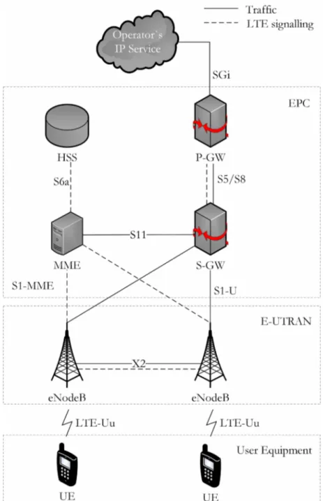
At a high level, EPS has three main elements: the Evolved Packet Core (EPC), Evolved UMTS Terrestrial Radio Access Network (E-UTRAN), and the User Equipment
(UE).
While the EPC consists of many logical nodes, the access network is made up of essentially just one node, the evolved NodeB (eNodeB), which connects to the UEs. Figure 2.5 shows the main elements of the EPC and the interfaces that connect the elements of the EPS. Next, we describe each one of these elements in more details.
2.2.1 User Equipment
The User Equipment (UE) can be divided in two parts: the Mobile Termination (MT), responsible for all communication functions, and the Terminal Equipment (TE), which terminates the data streams. For instance, the mobile termination might be a plug-in LTE card for a laptop and the terminal equipment would be the laptop itself [2].
The UE has a smart card called Universal Integrated Circuit Card (UICC). The UICC is also colloquially known as the SIM card. This card run an application known as Universal Subscriber Identity Module (USIM). This application stores user-specific data such as the user’s phone number and home network identity. USIM is also used to identify and authenticate the user and to derive security keys for protecting the radio interface transmission [31].
Figure 2.5: The EPS network elements.
2.2.2 E-UTRAN
The E-UTRAN is responsible for the radio communication between the UE and the EPC. The E-UTRAN is composed solely by the eNodeB. Each eNodeB controls a set of UEs distributed in one or more cells. On the other hand, a UE communicates with just one eNodeB and belongs to one cell at time2.
The eNodeB is responsible for the Radio Resource Management (RRM). This means that the eNodeB handles, for example, the radio resource allocation, providing the required Quality of Service (QoS). The eNodeB also handles the low-level operation of all its UEs, by sending them signaling messages related to those radio transmissions, such as handover commands [2].
As one can see in Figure 2.5, the eNodeB presents three interfaces. The X2 interface, between two eNodeBs, which is mainly used for signaling and packet forwarding during handover. The Sl-U interface, between eNodeB and Serving Gateway (S-GW), which is used for user plane traffic. The Sl-MME interface, between eNodeB and the Mobile Management Entity (MME), which is used for control plane traffic.
2.2.3 Evolved Packet Core
The EPC is the main component of the SAE. It consists of the following functional elements:
• Serving Gateway (S-G W ): all IP packets of users are transferred through the S-GW, which serves as the local mobility anchor for the data bearers when the UE moves between eNodeBs.
• Packet Data Network (PDN) Gateway (P-G W ): the P-GW is the EPC’s point of contact with the outside world. Through the SGi interface, each PDN gateway exchanges data with any external devices or packet data networks.
• Mobility Management Entity (MME): the MME is the key control element for the LTE access network. It is responsible for authenticating the user, UE tracking and paging procedure. It is also responsible for choosing the S-GW for UEs and it provides the control plane function for mobility between LTE and 2G/3G access networks.
• Home Subscriber Server (HSS): the HSS contains users’s SAE subscription data such as the EPS-subscribed QoS profile and any access restrictions for roam ing. It also holds information about the PDNs to which the user can connect. In addition, the HSS holds dynamic information such as the identity of the MME to which the user is currently attached or registered.
2.3 Protocol Architecture
Each one of the interfaces indicated in Figure 2.5 is associated with a protocol stack, which the network elements use to exchange data and signalling messages. The protocol architecture is divided in two groups:
• user plane: protocols used to handle data of interest of the user.
• control plane: protocols used to handle signalling messages.
Considering the air interface (Uu), we have the definition of two more terms: Access Stratum (AS) and Non Access Stratum (NAS). Access Stratum is a functional layer defined to allow the communication in the air interface between the UE and the eNB. In contrast, the Non Access Stratum is another functional layer defined to provide communication between the UE and the core network elements. In short, the distinction is that the AS is for explicit dialogue between the UE and the radio network, while the NAS is for dialogue between the UE and core network nodes that is passed transparently through the radio network.
2.3.1 User Plane Protocols
Figure 2.6 shows an overview of the user plane protocols.
Figure 2.6: User plane protocol stacks (Adapted from [2]).
• Packet Data Convergence Protocol (PDCP): is responsible for higher-level transport functions that are related to header compression and security.
• Radio Link Control (RLC): the main functions of the RLC layer are segmen tation and reassembly of upper layer packets. In some configurations, this layer is also responsible for ensuring reliable delivery for data streams that need to arrive correctly.
• Medium Access Control (M AC): this layer performs multiplexing of data from different radio bearers and is responsible for scheduling data transmissions between the mobile and the base station.
In the Sl-U and S5/S8 interfaces the GPRS Tunneling Protocol User Part (GTP-U) handles the data flow between the pairs eNB/S-GW and S-GW/P-GW.
2.3.2 Control Plane Protocols
Figure 2.7 shows an overview of the control plane protocols.
Figure 2.7: Control plane protocol stacks (Adapted from [2]).
On the air interface Uu, the control messages are handled by the Radio Resource Control (RRC) protocol. In the SI interface, the MME controls the base stations using the SI Application Protocol (Sl-AP). The Stream Control Transmission Protocol (SCTP) is a TCP-based protocol that includes extra features that make it more suitable for the delivery of signalling messages.
through which a mobile communicates with the outside world, and EPS Mobility Man agement (EMM), which handles internal bookkeeping within the EPC. The network transports EMM and ESM messages by embedding them into lower-level RRC and Sl AP messages and then by using the transport mechanisms of the Uu and SI interfaces
[2
]-2.4 Logical, Transport and Physical Channels
The information that flows between the different protocols are known as channels. Fig ure 2.8 shows the air interface protocol stack from the UE point of view. This figure also indicates the location of the different channels between the protocols. LTE uses several different types of logical, transport and physical channels, which are distinguished by the kind of information they carry and by the way in which the information is processed. The physical layer can be divided in three parts: (i) the transport channel processor is responsible for the error management procedures; (ii) the physical channel proces sor applies the techniques of OFDMA, SC-FDMA and multiple antenna transmission; (iii) finally, the analogue processor converts the signal to be transmitted. In the next sections, we offer more details of how these channels work.
2.4.1 Logical Channels
Table 2.1 lists the logical channels. One can see that there are channels reserved for user and control plane purposes. The most important logical channels are the Dedi cated Traffic Channel (DTCH), which carries data to or from a single mobile, and the Dedicated Control Channel (DCCH), which carriers most of signalling messages.
Table 2.1: LTE logical channels.
Channel Name Information carried
DTCH Dedicated Traffic Channel User plane data
DCCH Dedicated Control Channel Signalling
CCCH Common Control Channel Signalling
PCCH Paging Control Channel Paging messages
Figure 2.8: Air interface protocol stack (Adapted from [2]).
2.4.2 Transport Channels
The transport channels are listed in Table 2.2. The most important transport channels are the Downlink Shared Channel (DL-SCH) and the Uplink Shared Channel (UL-SCH), which carry the majority of data and signalling messages in the air interface. These two channels are the only transport channels allowed to adapt their coding rate according to the channel quality. They can also make use of techniques of automatic repeat request to recover from transmission losses.
Table 2.2: LTE transport channels.
Channel Name Information carried
DL-SCH Downlink Shared Channel Downlink data and signalling UL-SCH Uplink Shared Channel Uplink data and signalling
RACH Random Access Channel Random Access Request
PCH Paging Channel Paging messages
BCH Broadcast Channel Master information block
MCH Multicast Channel MBMS data
2.4.3 Physical Channels
Table 2.3 lists the LTE physical channels. The most important physical channels are the Physical Downlink Shared Channel (PDSCH) and the Physical Uplink Shared Channel (PUSCH). PDSCH carries data from DL-SCH and PCH. PUSCH is responsible for transporting data from UL-SCH. These two channels are the only physical channels allowed to change their modulation schemes in response to channel quality variations.
Table 2.3: LTE physical channels.
Channel Name Information carried
PDSCH Physical Downlink Shared Channel DL-SCH and PCH
PUSCH Physical Uplink Shared Channel UL-SCH
PRACH Physical Random Access Channel RACH
PBCH Physical Broadcast Channel BCH
PMCH Physical Multicast Channel MCH
PDCCH Physical Downlink Control Channel DCI
PUCCH Physical Uplink Control Channel UCI
PCFICH Physical Control Format Indicator Channel CFI
PHICH Physical Hybrid ARQ Indicator Channel HI
Table 2.3 also lists the physical control channels. These channels are related to specific control information. Table 2.4 enumerates the types of control information used in LTE.
Table 2.4: LTE control information.
Channel Name Information carried
DCI Downlink Control Information Downlink scheduling commands Uplink scheduling grants Uplink power control commands
UCI Uplink Control Information
Hybrid ARQ acknowledgements Channel Quality Indicator (CQI) Pre-coding Matrix Indicators (PMI) Rank Indications (RI)
Scheduling Requests (SR) CFI Control Format Indicator Size of downlink control region
HI Hybrid ARQ Indicator Hybrid ARQ acknowledgements
The Uplink Control Information (UCI) has several fields. HARQ ACKs (Hybrid ARQ Acknowledgements) are used to acknowledge the packets received on the DL- SCH. The Channel Quality Indicator (CQI) describes the quality of the connection between the UE and the base station. The Pre-coding Matrix Indicators (PMI) and Rank Indications (RI) are used to support multiple antenna techniques. Scheduling Requests (SR) are sent by the mobile, asking for resources to transmit on the PUSCH.
Control Format Indicators (CFI) describe the data organization in the downlink. HARQ Indicators (HI) are used to acknowledge packets received on the UL-SCH.
2.5 Summary
- Christian Lous Lange
3
Resource Allocation in the LTE Network
Co m m u n ic a t io n n e t w o r k s are designed to serve a particular number of users. How
ever, the network resources are always limited, and they have to be split among the users. This process is called resource allocation. In this chapter, we present a brief description of how the LTE network shares its resources among the UEs.
3.1 Physical Layer Design
Multiple access techniques allow the base station to communicate with several mobile terminals simultaneously. As we said in Section 2.1.4, LTE uses OFDMA and SC- FDMA as the techniques for multiple access in downlink and uplink, respectively. In the next sections, we describe how these techniques work and their main differences.
3.1.1 OFDMA
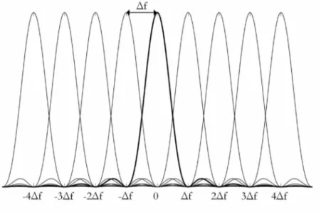
Quadrature Phase Shift Keying (QPSK) or 16-QAM, for example. The use of orthogo nal subcarriers is also important to mitigate the Inter Symbol Interference (ISI). Figure 3.1 shows how the subcarriers are spaced in a manner that the interference among them is decreased. At the instant the amplitude of a particular subcarrier is sampled, the amplitude of the other subcarriers equals zero. In LTE, the subcarrier spacing (A f) is equal to 15 kHz.
OFDMA is efficiently implemented via Fast Fourier Transform (FFT) and also present other advantages like high spectral efficiency and bandwidth scalability [4].
Figure 3.2 illustrates a block diagram of the OFDMA transmitter used by the eN- odeB. In OFDMA transmission, each symbol is mapped to a particular subcarrier. Therefore, each subcarrier only carries information related to one specific symbol.
OFDMA works well in the downlink. However, despite of the set of advantages, OFDMA has one disadvantage: it presents a large variation in the power of the trans mitted signal. These variations require the use of large and expensive power amplifiers, which can deal with the power variations without reaching the saturation region. The base station can afford this kind of power amplifiers. However, the same is not true for the UEs. The mobile transmitter must be cheap, small and energy efficient. This fact makes OFDMA unsuitable for the uplink.
3.1.2 SC-FDMA
Figure 3.2: Block Diagram of the OFDMA transmitter (Adapted from [2]).
placing them into the subcarriers, we might be able to adjust the transmitted signal and reduce its power variation.
One of the most suitable mixing operation is a forward FFT. In this sense, SC- FDMA uses a forward FFT to mix the symbols and avoid large power variations. The process is depicted in Figure 3.3.
Besides the addition of the forward FFT before the resource element mapping, we also can identify the following difference between OFDMA and SC-FDMA: the first difference arises because the technique is used on the uplink. Because of this, the mobile transmitter uses only some of the subcarriers. The others are set to zero, and are available for the other mobiles in the cell. The second difference is given by the fact that each mobile transmits using a single, contiguous block of subcarriers, without any internal gaps. This is necessary to keep the power variations as lowest as possible [2].
Figure 3.3: Block Diagram of the SC-FDMA transmitter (Adapted from [2]).
In the example, there are four subcarriers. For OFDMA, four symbols are used in parallel to modulate their own subcarrier. Each data symbol occupies 15 kHz for the period of one OFDMA symbol (66.7 ^s). The parallel transmissions allow the data symbols be the same length as the OFDMA symbols.
In the SC-FDMA case, the data symbols are transmitted sequentially. In this sense, four data symbols are transmitted sequentially in one SC-FDMA symbol period. The SC-FDMA symbol period is the same length as the OFDMA symbol. However, because of sequential transmission, the data symbols are shorter being 66.7/M^s, where M is the number of subcarriers. This phenomenon requires more bandwidth, so each data symbol occupies 60 kHz of spectrum rather than the 15 kHz used in OFDMA [32].
OFDMA
Data symbols occupy 15 kHz for one OFDMA symbol period
SC-FDMA
Data symbols occupy M‘ 15 kHz for 1/M SC-FDMA symbol periods
Figure 3.4: Comparison of OFDMA and SC-FDMA transmitting a series of QPSK data symbols [32].
more specifically, in Release 10 the uplink resource assignment consist of a maximum of two frequency-separated groups of RBs [27]. Then, the contiguity constraint can be broken, but only for two clusters of resource blocks. In practice, this gives more flexibility to the scheduling algorithm, but the constraint still need to be considered.
3.2 Cyclic Prefix
Besides the subcarrier spacing, LTE also makes use of the cyclic prefix insertion to minimize the effects of the interference in the reception of the symbol. The cyclic prefix insertion consists of a technique in which an ending piece of the symbol is copied to its front. Figure 3.5 shows the cyclic prefix insertion operation.
3.3 The Resource Grid Structure
Figure 3.5: Operation of cyclic prefix insertion (Adapted from [2]).
the base station resources are grouped and organized to optimize the allocation process.
The symbols are grouped into slots, whose duration is 0.5 ms. This grouping can be performed in two ways [2]:
• normal cyclic prefix: each symbol is preceded by a cyclic prefix that is usually 4.7 ^s long. The first cyclic prefix is set to 5.2 ^s, since it is not possible to fit seven symbols of the same size into a slot.
• extended cyclic prefix: each symbol is preceded by a cyclic prefix of 16.7 ^s. In this configuration, the number of symbols in the slot is reduced to six.
Using the normal cyclic prefix the receiver can deal with ISI presenting a delay spread of 4.7 ^s, corresponding to a path difference of 1.4 km between the lengths of the longest and shortest rays. This is normally enough. However, for unusually larger cells, the extended cyclic prefix may be more appropriated, since it supports a maximum path difference of 5 km and delay spread of 16.7 ^s. Figure 3.6 shows the organization of the symbols into slots using these two approaches.
At a higher level, slots are grouped into sub-frames. In FDD mode, two slots form a sub-frame of 1 ms. Sub-frames are defined for scheduling purposes. When the eNodeB transmit to a UE, it schedules its transmissions one sub-frame at time. The sub-frame is also known as the Transmission Time Interval (TTI). In the uplink, the process is similar.
A sequence of 10 sub-frames form a frame of 10 ms. Figure 3.7 depicts the LTE frame structure type 1, used in the FDD mode. There is also a frame structure type 2, used in TDD mode. In this thesis, we will work only with FDD mode. Interested readers can get more information about frame structure type 2 in [2].
<--- Slot 0.5 ms---►
Normal Cyclic Prefix
4.7jas 66.7jlis
Extended Cyclic Prefix
16.7|as 66.7jas
Figure 3.6: Organization of symbols into slots using the normal and extended cyclic prefixes.
Figure 3.7: Frame structure type 1, used in FDD mode.
considering the normal cyclic prefix. The basic unit is the resource element, which is formed by one symbol in time and one subcarrier in frequency. Resource elements are grouped into Resource Blocks (RB). Each RB spans one slot (0.5 ms) by 180 kHz (12 subcarriers). In this sense, the RB is the unit used by the base station to allocate its resources among the mobiles.
3.4 Bandwidth
Figure 3.8: LTE resource grid considering the normal cyclic prefix (Adapted from [2]).
for the deployment of LTE. For example, 1.4 MHz is close to the bandwidth earlier used by cdma2000, 5MHz is the same bandwidth used by WCDMA, while 20 MHz allows an LTE base station to operate at its highest possible data rate1 [2].
Table 3.1: LTE supported bandwidths.
Bandwidth Number of RBs Number of subcarriers
1.4 MHz 6 72
3 MHz 15 180
5 MHz 25 300
10 MHz 50 600
15 MHz 75 900
20 MHz 100 1200
![Figure 2.2: Convergence of wireless technologies (Adapted from [27]).](https://thumb-eu.123doks.com/thumbv2/123dok_br/15993718.690829/34.892.139.791.403.752/figure-convergence-wireless-technologies-adapted.webp)
![Figure 2.3: LTE releases (Adapted from [27]).](https://thumb-eu.123doks.com/thumbv2/123dok_br/15993718.690829/35.892.208.736.145.604/figure-lte-releases-adapted.webp)


![Figure 2.8: Air interface protocol stack (Adapted from [2]).](https://thumb-eu.123doks.com/thumbv2/123dok_br/15993718.690829/44.892.239.697.151.759/figure-air-interface-protocol-stack-adapted.webp)
![Figure 3.2: Block Diagram of the OFDMA transmitter (Adapted from [2]).](https://thumb-eu.123doks.com/thumbv2/123dok_br/15993718.690829/49.892.318.615.159.647/figure-block-diagram-ofdma-transmitter-adapted.webp)
![Figure 3.4: Comparison of OFDMA and SC-FDMA transmitting a series of QPSK data symbols [32].](https://thumb-eu.123doks.com/thumbv2/123dok_br/15993718.690829/51.892.161.785.149.555/figure-comparison-ofdma-fdma-transmitting-series-qpsk-symbols.webp)

