UNIVERSIDADE FEDERAL DE SÃO CARLOS CENTRO DE CIÊNCIAS EXATAS E DE TECNOLOGIA
PROGRAMA DE PÓS-GRADUAÇÃO EM CIÊNCIA E ENGENHARIA DE MATERIAIS
FRICTION SURFACING OF ALUMINUM ALLOY 5083-H112 OVER AA 2024-T3
Samuel Hernandes Silvério
UNIVERSIDADE FEDERAL DE SÃO CARLOS CENTRO DE CIÊNCIAS EXATAS E DE TECNOLOGIA
PROGRAMA DE PÓS-GRADUAÇÃO EM CIÊNCIA E ENGENHARIA DE MATERIAIS
FRICTION SURFACING OF ALUMINUM ALLOY 5083-H112 OVER AA2024-T3
Advisor: Dr. Nelson Guedes de Alcântara. Grant Agency: CNPq
Process: 155317/2014-8
São Carlos 2018
Samuel Hernandes Silvério
RESUME
ACKNOWLEDGMENTS
Firstly, I would like to express my gratitude to Dr. Henning Krohn and Viktoria Fitseva, my scientific advisors at the Helmholtz-Zentrum Geesthacht, for the orientation, availability and willingness to share their knowledge.
To Prof. Dr. Nelson Guedes de Alcântara, I phrase my appreciation, for the opportunity, trust, support, attention, motivation and encouragement provided during the development of my work. I am also grateful to Dr. Jorge dos Santos, for the work opportunity created in HZG.
This study was financed in part by the Coordenação de Aperfeiçoamento de Pessoal de Nível Superior - Brasil (CAPES) - Finance Code 001"
I also want to thank CNPq for the financial support during the duration of the project.
ABSTRACT
Friction surfacing of aluminum alloy 5083-H112 over AA 2024-T3
Friction surfacing (FS) is an advanced solid-state process in surface modification with increasing applications in reclaiming worn parts, hardfacing and corrosion protection. It is considered a derivation of the friction stir welding process, keeping many benefits of the primary process such as: solid phase, forged microstructure and excellent metallurgical bond. As no melting takes place, the process allows dissimilar joining of materials while avoiding several fusion related problems. The present study addresses the deposition of AA5083-H112 coatings over AA2024-T3 substrates, focusing on the influence of the thermo-mechanical process in the mechanical properties and geometry of the deposits. A performance and geometric analysis of the depositions are also presented. Sound aluminum coatings were produced; plastic deformation and heat generation promotes a dynamic recrystallization of the anisotropic consumable rod, resulting in a fine and homogeneous deposit, free of any previous deformation. The coating presented an increase in ultimate tensile strength and failure deformation of 9% and 6%, respectively. Deposition efficiency between 25 and 50% were obtained, with a maximum of 48% average efficiency observed with 800RPM, 12kN and 16mm/s.
RESUMO
Deposição por fricção de AA 5083-H112 sobre AA 2024-T3
A deposição por fricção (FS) é um avançado processo de modificação da superfície no estado sólido, com aplicações crescentes na recuperação de peças desgastadas, proteção contra corrosão e revestimento. É considerada uma derivação do processo de soldagem por fricção, mantendo muitos benefícios do processo primário, tais como: fase sólida, microestrutura forjada e excelente ligação metalúrgica. Como não ocorre fusão dos materiais envolvidos, o processo permite a união dissimilar de materiais, evitando vários problemas relacionados com a fusão. O presente estudo aborda a deposição da liga de alumínio 5083-H112 sobre substratos AA2024-T3, estudando sua viabilidade técnica e focando na influência do processo termomecânico nas propriedades mecânicas e geometria dos depósitos. Também são apresentados uma análise de desempenho e geométrica das soldas. A deposição das ligas foi realizada com sucesso. A deformação plástica e a geração de calor promovem uma recristalização dinâmica da até então estrutura anisotrópica do bastão consumível, resultando num depósito com microestrutura fina e homogênea, livre de qualquer deformação anterior. O depósito apresentou um aumento na resistência à tração e à deformação de ruptura de 9% e 6%, respectivamente. A eficiência de deposição obtida foi entre 25 e 50%, com um máximo de 48% de eficiência média observada com 800 RPM de velocidade rotacional, 12 kN de forca axial e 16 mm/s de velocidade transversal.
PUBLICATIONS
TABLE OF CONTENTS
DISSERTATION COMMITTEE ... i
ACKNOWLEDGMENTS ... iii
ABSTRACT ... v
RESUMO ... vii
PUBLICATIONS ... ix
TABLE OF CONTENTS ... xi
TABLE LIST ... xiii
FIGURE LIST ... xv
SYMBOLS AND ABBREVIATIONS... xvii
1 INTRODUCTION ... 1
2 OBJECTIVES ... 5
3 LITERATURE REVIEW ... 7
3.1 Friction Surfacing ... 7
3.1.1 The Process ... 7
3.1.2 Heat Affected Zone ... 11
3.2 Aluminum alloys strengthening mechanisms ... 13
3.2.1 Precipitation hardening ... 14
3.2.2 Strain hardening ... 14
3.3 Aluminum alloys Al-Cu-Mg: AA2024 ... 16
3.4 Aluminum alloys Al-Mg: AA5083 ... 17
4 MATERIALS AND METHODS ... 19
4.1 Material and equipment ... 19
4.2 Metallurgical analysis ... 24
4.3 Mechanical characterization ... 26
4.3.1 Microhardness test ... 26
4.3.2 Tensile test ... 26
5 RESULTS AND DISCUSSION ... 29
5.1. Metallurgical analysis ... 30
5.2 Mechanical analysis ... 34
5.3 Influence of process parameters ... 39
7 RECOMMENDATIONS FOR FUTURE WORK ... 45
TABLE LIST
Table 1.1: Reported FS material depositions over steel substrates………. 2
Table 1.2: Reported FS material depositions over non-ferrous substrates…... 2
Table 3.1: Basic temper designations……….. 13
Table 3.2: Chemical composition of the alloy 2024………... 16
Table 3.3: Chemical composition of the alloy AA5083……….. 18
Table 4.1: Nominal mechanical properties of AA 2024-T3………... 20
Table 4.2: Nominal mechanical properties of AA 5083-H112……….. 20
Table 4.3: Process window on the proceedings………. 22
FIGURE LIST
Figure 3.1: Schematic representation of the Friction surfacing process.………. 7
Figure 3.2: The material of the consumable rod deposited in order to form a layer and discharged outside as flash………..………….………….... 8
Figure 3.3: Representative graph of monitoring the parameters of the friction
surfacing process……….…………. 9
Figure 3.4: Deposit on the substrate surface by the friction surfacing
process……….……….…. 9
Figure 3.5: Cross section of the middle and end of the layer, showing the undercut………...…. 10
Figure 3.6: Schematic representation of the heat affected zone resulting from Friction Surfacing process………. 12
Figure 3.7: Distribution of measured heat input rate to coating material and laterality moving substrate………. 12
Figure 3.8: Scheme of the evolution of mechanical properties and microstructure, verified during annealing……… 15
Figure 3.9: Precipitates in the microstructure of the aluminum alloy 2024 hardened by precipitation………..…… 17
Figure 4.1: Representation of the geometry of the materials used in the project……… 19
Figure 4.2: RAS machine used in the friction surfacing process………..…….. 21
Figure 4.3: (a) Dimensions of the samples (mm) and (b) Picture of the sample produced by electro-erosion……….. 23
Figure 4.4: (a) Cross-section cut on the deposit and (b) cross-section showing the location of micro-specimens for the tensile test……….. 24
Figure 4.6: Schematic representation of the indentation line in the cross section of the deposit and substrate during the hardness test……….. 26
Figure 4.7: Special specimen adaptor... 27
Figure 5.1: Graph of monitoring the parameters of the friction surfacing process of sample 284……….. 29
Fig 5.2: As-received AA5083-H112 consumable rod microstructure: (a) perpendicular to rod extrusion direction; (b) parallel to rod extrusion
direction……… 31
Fig 5.3: Coating cross section macrograph: (a) bonding interface; (b) coating
microstructure………... 33
Figure 5.4: Stress-Strain curve of the deposit achieved for the condition 800 RPM, 12kN and 16mm/s... 35
Figure 5.5: Average yield strength x conditions of deposition…...……….. 36
Figure 5.6: Average ultimate strength x conditions of deposition………..……. 36
Figure 5.7: Failure deformation strain x conditions of deposition………..……. 37
Figure 5.8: Effect of rotational speed on hardness profile along coating centreline... 38
Figure 5.9: Hardness profile along the substrate, showing the heat affected zone... 38
Figure 5.10: Main effects plot for maximum width………. 40
Figure 5.11: Main effects plot for thickness……… 40
Figure 5.12: Main effects plot for efficiency….……….. 41
SYMBOLS AND ABBREVIATIONS
AA aluminum alloy
EDM electro discharge machine FS friction surfacing
HAZ heat affected zone
Friction surfacing (FS) is an advanced solid-state process in surface modification [1], it was first patented as metal coating process in 1941 by Klopstock [2] and it derives from the friction stir welding, keeping many benefits of the primary process such as: solid phase, forged microstructure and excellent metallurgical bond. Completing the advantages list, the process is environmentally clean with no fumes, spatter or high energy light emissions, it is energy efficient considering the heat is generated exactly where is demanded [3], it allows the use of metallurgically incompatible materials and, as it happens in the solid phase (no melting involved), the dilution of the material of the consumable into the substrate is negligible, what maintains good adhesion properties [4]. Since this is a solid-state process, there is no occurrence of pores, slag or inclusions, as is characteristic of traditional processes which involve melting as the arc welding process [5]. Regarding the process, it demands high forces to be concluded and one disadvantage is the higher stiffness the machine should have.
The friction surfacing process is mostly applied for corrosion and wear resistant coatings and to reclaim worn engineering components [6]. More specific applications include the fabrication of machine knives for the food and pharmaceutical processing and packaging industries, the hardfacing of valve seats with stellite – typical hardfacing alloys which are cobalt-based alloys with high hardness at high temperature and corrosion resistance and high wear resistance under high-pressure conditions, the repair and manufacture of parts for the gas turbine industry and some types of tooling as punches and drills [7].
Table 1.1: Reported FS material depositions over steel substrates [8]
2. OBJECTIVES
3. LITERATURE REVIEW
3.1 Friction Surfacing
3.1.1 The Process
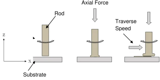
Friction surfacing is a solid-state coating process based on the plastic deformation of a metallic consumable rod, it involves a high complexity of transformations, combining both hot-working and joining principles. As other friction-based manufacturing technologies, a viscoplasticized solid state region is generated and processed into a new shape and metallurgical condition [8]. Figure 3.1 shows a schematic representation of the process.
Figure 3.1: Schematic representation of the Friction surfacing process.
The process starts when the consumable rod is positioned above the area that will be coated. The rod starts to rotate with a certain rotational speed and then an axial force is applied in the top of the rod, pressing it tightly against the substrate. The axial force and the rotational speed lead to an intense frictional heat production due to the friction generated at the rubbing surface between the substrate and the coating rod [7]. As the substrate is bigger in volume and it is more efficient in transfer the heat compared to the consumable rod, the heat exchange in the substrate has a higher speed than in the rod. This means that the heat produced concentrates at the bottom end of the rod where a large axial
Rod
Substrate
Axial Force
temperature gradient occurs, and not in the substrate itself [1, 5]. As a consequence of the friction heat produced, the material of the rod’s tip becomes plasticized. Combining the rotational speed and the traverse movement, the material plasticized of the rod is transferred to the substrate in order to form the layer, as can be seen in Figure 3.1. Notice that not all the material of the consumable rod is deposited on the substrate during friction surfacing as part of the rod is discharged outside as what is called “flash”, as showed in Figure 3.2. A probable cause for the formation of the flash is the skidding between the consumable rod and the friction surface, which is increased in processes involving higher axial force and rotational speeds [7].
Figure 3.2: The material of the consumable rod deposited in order to form a layer and discharged outside as flash.
The bigger the flash, the less efficient the processes because less material is transferred to the substrate in order to form the layer [7]. One possible calculation of efficiency is to compare the volume spent of the consumable rod with the volume of the layer produced.
The main parameters of friction surfacing process are the rotational speed, axial force and traverse speed, as shown in Figure 3.3. The first vertical dotted line indicates the beginning of consumable rotation, the second indicates when the axial force is applied over the end of the consumable that is coupled to the equipment and, finally, the third indicates the beginning of the substrate transverse displacement.
dependent on material characteristics, but the parameters are capable to make significant effects on dimensions and quality of the deposited layer [9].
Figure 3.3: Representative graph of monitoring the parameters of the friction surfacing process.
At the end of the process, the result is a deposit on the substrate surface, as shown in Figure 3.4.
Figure 3.4: Deposit on the substrate surface by the friction surfacing process.
substrate - and the other is the maximum width – that takes account the whole layer, till its edges - although this is not a real bond.
Figure 3.5: Cross section of the middle and end of the layer, showing the undercut [10].
Two possible reasons for this "lack" of weld is an inefficient transmission of the axial force – friction pressure – to the outer regions of the consumable rod based on the fact the pressure decreases due to the formation of the flash from the consumable rod [7]; and the fact the zone for material transferring does not include the whole end surface of the consumable rod [1].
pressed against the substrate without lateral restraint, flowing outside the consumable rod diameter region. This promotes the development of a revolving flash as well as the lack of bonding at the coating edges on both the advancing (rotation and travel movements are in the same direction) and retreating sides (rotation and substrate movement are in opposite directions), as described by Nicholas and Thomas [15]. Hence, the fully bonded width of the deposits produced by FS is typically less than the diameter of the consumable, as reported by Nicholas [16]. Nevertheless, flash and unbounded edges play an important role, providing temperature and pressure boundary conditions for the joining process, as was evidenced by Vilaca et al. [17].
3.1.2 Heat Affected Zone
Heat affected zones are regions of the material subjected to thermal cycling during the welding process, but suffer no plastic deformation [6]. The grain structure is maintained in this region, but the dislocation density is altered and with the thermal exposure there are some effects on the precipitate structure like coarsening of the strengthening particles; these comparisons are relatively to a non-affected zone of the substrate [18].
In the friction surfacing process, the HAZ is substantially smaller comparing to other surfacing processes based on fusion and laser processes, because instead the whole component reaches high temperatures, the heating is only local and although the whole component becomes hot, the temperatures are not high enough to affect the properties of the substrate prejudicially [12].
Figure 3.6: Schematic representation of the heat affected zone resulting from Friction Surfacing process [12].
The depth of HAZ is a function of the temperature at the coating/substrate interface [12] and its cross-sectional area is function of the heat input into substrate [3]. The heat input represents a measurement of the mechanical power supplied by the equipment and it’s a function of rotational speed, axial force and transverse speed.
According to Shinoda [9], increasing the rotational speed almost doesn’t change the total heat input rate, however, heat input rate into coating material increases with increasing rotation speed. Therefore, heat input into substrate and rod can be controlled by changing rotation speed [9].
Figure 3.7: Distribution of measured heat input rate to coating material and laterality moving substrate [9]
substrate becomes smaller [14], what explains why the cross-sectional area of the HAZ decreases.
3.2 Aluminum alloys strengthening mechanisms
Aluminum alloys can have their strength enhanced by different processing methods, either heat or non-heat treatable alloys. There are five basic wrought aluminum temper designations, of which, the most commonly used are the T (thermally treated) and H (strain hardened) tempers, as can be seen in Table 3.1. These two tempers classes are valued for their ability to provide high strength-to-weight ratio alloys: The H temper, by work hardening, and the T temper, by precipitation hardening [19].
Table 3.1: Basic temper designations
F As fabricated
O Annealed
W Solution heat-treated
T Thermally treated
H Strain-hardened
3.2.1 Precipitation hardening
This method will only be possible if the aluminum alloy contains an element, such as Copper (Cu), Zinc (Zn), Silicon (Si) and/or Magnesium (Mg), which has a decreasing solubility in aluminum at decreasing temperatures.
The strengthening process by precipitation is performed in three different steps: solubilization or solution heat-treating, quenching to a lower temperature and, finally, ageing. The final mechanical properties of the alloy will be defined during the ageing stage by controlling the time and temperature in which this step take place. These steps will allow the formation of precipitates that will act like barriers for the dislocation movements and this difficult applied to dislocations movements will be seen as an increase in the strength of the alloy. There must be a control on the size and dispersion of this precipitates for a better result in the treatment [19].
3.2.2 Strain hardening
Non heat-treatable alloys are mostly work hardened to produce a strain-hardened temper. The cold work produces entanglement of internal dislocations and the increase of its density will lead to an increase in strength with a decrease in ductility. This dislocation structure resulting from the cold work is less stable then the strain-free, annealed state [20].
Figure 3.8: Scheme of the evolution of mechanical properties and microstructure, verified during annealing [20].
During the recovery, due the temperature and/or time applied, the dislocations are greatly reduced in number and often rearranged into a cellular sub-grain structure, and with that the internal stresses induced by cold work will be reduced. With increasing time and heating temperature, recovery proceeds and sub-grain size gradually increases [20].
3.3 Aluminum alloys Al-Cu-Mg: AA2024
Among the applications in which aluminum alloys are employed, a highlight is on the aircraft structure due to the combination of low density and high mechanical strength, meaning a high specific strength. In aluminum alloys the movement of dislocations is the main plastic deformation mechanism. A high specific resistance of Al-Cu alloys or alloy of the series 2xxx, occurs due to difficulties imposed to the motion of dislocations due to the presence of precipitates, being called precipitation hardened alloys [21].
The precipitation hardening mechanism is constituted by a solubilization stage of the alloying elements, followed by quenching and aging, when the precipitation occurs. The condition that allows an alloy is hardened by precipitation is that the second phase or precipitate is soluble at elevated temperature and that the solubility decays as it lowers the temperature [22]. This condition is visually examined by observing the Cu-Al phase diagram [23].
The alloy of the series 2xxx in which there is the addition of Mg in substantial proportions is called 2024 aluminum alloy and its chemical composition is shown in Table 3.2 [24].
Table 3.2: Chemical composition of the alloy 2024 [25].
Al Cr Cu Fe Mg Mn Si Ti Zn Remaining
90.7 -
94.7% ≤ 0.10%
3.8 -
4.9% ≤ 0.50%
1.2 - 1.8%
0.30 -
0.90% ≤ 0.50% ≤ 0.15% ≤ 0.25% ≤ 0.15%
A heat treatment used to provide precipitation hardening in the AA 2024 is described by the abbreviation T3, which involves treatment of solubilization, when all phases are dissolved, followed by quenching, which aims to achieve a supersaturation which allow precipitation or aging. The solution temperature is 495 ° C, followed by natural aging [27].
The resulting microstructure of the aging process of the aluminum alloy 2024 is similar to the alloys of the 2xxx series, with additional precipitates that are also contains magnesium, as can be seen in Figure 3.9 [28].
Figure 3.9: Precipitates in the microstructure of the aluminum alloy 2024 hardened by precipitation [28].
3.4 Aluminum alloys Al-Mg: AA5083
markedly the strength of aluminum is increased without decrease the ductility overmuch [29]. The most important feature of Al-Mg alloys is the corrosion resistance, also considering exposure to seawater and marine atmospheres. They also offer excellent weldability and good machinability [30].
When the contents of magnesium are greater than 7.0%, the alloy is characterized as heat treatable, although heat treatments are more used to stabilize properties, which can change with the time [30].
The AA5083 is a non-heat-treatable alloy having magnesium as the major alloying element as it is presented in the Table 3.3.
Table 3.3: Chemical composition of the alloy AA5083 [25].
Al Cr Cu Fe Mg Mn Si Ti Zn Remaining
92.4 - 95.6%
0.05-0.25% ≤ 0.10% ≤ 0.40%
4.0 – 4.9%
0.40 -
1.00% ≤ 0.40% ≤ 0.15% ≤ 0.25% ≤ 0.15%
The Al-Mg alloys are applied in food and beverage processing – due to the corrosion resistance, architectural and other decorative applications - in applications demanding excellent chemical response and attractive combination of strength and ductility [30]. The AA5083 is mostly applied in marine and aircraft applications, sceneries requiring a weldable moderate-strength alloy having good corrosion resistance.
4. MATERIALS AND METHODS
4.1 Material and equipment
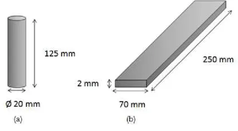
The materials used in this study were the aluminum alloys 2024-T3 and 5083-H112. AA 2024-T3 was used as a substrate in the form of a plate 250mm long, 70mm wide and 2mm thick. The AA 5083-H112 was used as a cylindrical consumable rod 125mm height and 20mm in base diameter. The schematic representations of the materials used and its dimensions are shown in Figure 4.1. These materials have been received with such shapes and dimensions and no machining process was needed after the friction surfacing process.
Figure 4.1: Representation of the geometry of the materials used in the project.
Table 4.1: Nominal mechanical properties of AA 2024-T3 [25]. AA 2024-T3 Yield strength (MPa) Vickers Hardness Ultimate tensile strength (MPa)
Failure strain [%]
290 145 435 16
Table 4.2: Nominal mechanical properties of AA 5083-H112 [25].
AA 5083-H112 Yield Strength (MPa) Vickers Hardness Ultimate tensile strength (MPa)
Failure strain [%]
190 88 300 15,5
Figure 4.2: RAS machine used in the friction surfacing process.
The substrate is attached to the machine table using clamping systems for both sides and the consumable rod is fixed at a device above the table. To start the process the table moves to the position defined in the x, y and z at the consumable. A computer monitoring software connected to the machine detects both the position of the consumable and the values of the process parameters; it also monitors the displacements along the axes, rotational speed, axial force and transverse speed.
Table 4.3: Process window on the proceedings. Rotational Speed [min‾¹] Axial Force [kN] Transverse Speed [mm/s]
800 12 12
1000 14 14
1200 16 16
The combination of all the individual conditions above results in all the deposition conditions, as can be seen in Table 4.4.
Table 4.4: Conditions of deposition proceedings.
Condition Rotational speed
[RPM]
Axial force
[kN]
Transverse speed
[mm/s]
1 800 12 12
2 800 12 16
3 800 16 12
4 800 16 16
5 1000 14 14
6 1200 12 12
7 1200 12 16
8 1200 16 12
The mechanical properties were obtained by tensile test using micro-specimens of the deposit. This type of test allows a detailed and local characterization of the mechanical properties. All micro‑specimens have a thickness of 0.5 mm and were extracted from the layers via electro discharge machining (EDM). The EDM is commonly used to cut mechanically hard materials and to machine complex patterns in metals and semiconductors. The process is based on electro-erosion of the work surface due to controlled high frequency electrical discharges through a dielectric medium. The geometry of the tool focuses the discharge to perform the desired machining operation. The geometry of micro specimens was designed based on standards DIN EN 2002001:200611 and DIN EN ISO 68921:2009‑12, as can be seen in Figure 4.3.
Figure 4.3: (a) Dimensions of the samples (mm) and (b) Picture of the sample produced by electro-erosion.
Figure 4.4: (a) Cross-section cut on the deposit and (b) cross-section showing the location of micro-specimens for the tensile test.
4.2 Metallurgical analysis
Optical microscopy was used to analyze the cross section of the deposit and substrate. The cross-sectional plane is described in Figure 4.4 (a). The analysis of the cross section will involve analysis of the adhesion between the deposit and the substrate and the dimensions of the deposit, represented by the thickness and width. This will be done for each combination of values of rotational speed, axial force and transverse speed. The dimensions of the deposit will be measured with the aid of the software ImageJ, which is an open source image processing program designed for scientific multidimensional images.
The samples for subsequent analysis via optical microscopy involves cutting the cross section of the deposit and the substrate, as shown in Figure 4.5, using a cutting machine Struers Discotom-6, and cold embedding these samples in transparent acrylic resin. Subsequently, the samples will be grinded using sandpaper 320, 600, 1200 and 2500. The samples will then be polished using 3μm diamond suspension, followed by OPS solution. Finally, in order to reveal the microstructure of both the deposit as the substrate, the samples will be etched using the electrolytic attack method with Bakers reagent for 120 seconds.
4.3 Mechanical characterization
4.3.1 Microhardness test
The microhardness test based on ASTM E384-11 was conducted on the cross section of the substrate and deposit with the aid of a device Zwick / Roell-ZHV by applying load of 0.2 kgf during a period of time of 10 seconds using a conventional indenter.
The indentations were conducted on the middle of the cross section of the substrate and deposit, completely covering the deposit, going across the heat affected zone and ending at the unaffected substrate. The number of indentations in the deposit and the substrate will depend on the width of the produced deposit, each indentation is separated from the other by 0.25 mm. Figure 4.6 shows a schematic representation of the indentation line made in the materials.
Figure 4.6: Schematic representation of the indentation line in the cross section of the deposit and substrate during the hardness test
In addition to hardness test in the cross section of the deposit and the substrate, the hardness test of the received material will be made (the consumable material and the substrate that were not submitted to friction surfacing process).
4.3.2 Tensile test
All of the mechanical tests were performed at ambient temperature, using a 5 kN electro mechanic universal testing machine with a constant transverse main displacement of 2 mm/min. The load was introduced using a special specimen adaptor; the samples were put in a ˝negative matrix˝ - without any clamping system, as shown in Figure 4.7, and then tested. The displacement was measured with a laser extensometer Fiedler PS50.
Figure 4.7: Special specimen adaptor
Nikolai et al. established and validated micro‑tensile and micro‑fatigue test technique. The results of their study showed that the proposed technique can be used to determine the tensile and fatigue properties of a small material volume and this technique is needed for small components, such as
investigating the property distribution in welds [33].
5. RESULTS AND DISCUSSION
The thermo-mechanical process of the friction surfacing consists of high complex transformations, involving joining and hot-working principles. AA5083 was successfully deposited on AA2024 by friction surfacing. Figure 5.1 depicts the registered evolution of both the torque and applied force on the consumable rod as well as the displacement along the consumable rod axial direction. The consumable rod had a 20 mm diameter and five different process stages were observed.
Figure 5.1: Graph of monitoring the parameters of the friction surfacing process for the condition 800 RPM, 16kN and 12mm/s
In the first stage, the machine develops the necessary torque to reach a consumable rotation speed of 800 rpm, after which it starts to move downward along z towards the substrate. At the beginning of third stage, the rotating rod is pressed against the substrate with a constant downward speed of 1 mm/s (rod feed rate control). The initial plastic deformation of the rod tip results in a drastic increase in both temperature and force up to a maximum of 18 kN. For a consumed length of 2.4 mm a crown of plastic material is fully developed. As temperature softens the rest of the consumable rod, both force and torque begin to drop, easing the on-going plunging to an approximately constant load of 16 kN. Torque begins to decrease gradually. For a 4 mm axial displacement, the consumable begins to travel over the substrate speeding to a velocity of 12 mm/s,starting the deposition phase. Rod vertical feed is now determined by the
0 10 20 30 40 50 60 70 0 5000 10000 15000 20000 T e m p o
1,23 2,46 3,69 4,92 6,15 7,38 8,61 9,84
axial force control and the equipment applies a constant force of 16 kN. This steady-state condition is also depicted by the approximately straight line displaying the axial displacement along the z axis. Notice that although the deposition was force controlled, the consumable rod axial displacement varied linear with time, meaning that the feed rate remained constant. After 60 mm length rod consumption, the equipment automatically interrupted the process by extracting the rod.
The initial deformation stage is associated with the generation of the amount of heat and plastic deformation, required to induce a dynamic recrystallization. These mechanisms are responsible for the decrease of load and torque as well as the temperature evolution during the initial deformation stage. This phenomenon marks the achievement of the necessary starting conditions for FS, i.e., the extension of the plunge period will only result in extra flash formation under constant axial load, with no significant temperature development and no benefits for joining strength. Similar results were also reported regarding FS of stainless steels over mild steel by Rafi et al. [34], copper over copper by Rao et al. [35], for aluminum alloys AA6082-T6 over AA2024-T3 by Gandra et al. [8] and AA5052 over AA2017 by Tokisue et al. [36].
5.1. Metallurgical analysis
Fig 5.2: As-received AA5083-H112 consumable rod microstructure: (a) perpendicular to rod extrusion direction; (b) parallel to rod extrusion direction.
For large plastic deformations, such as extrusion, the cold worked structure consists of very elongated grain structure containing a relatively equiaxial dislocation cells. On a more macroscopic scale, the severely cold worked metal structure is characterized by the development of a strong crystallographic texture. The presence of preferred orientation causes anisotropy of mechanical properties. Therefore, as can be seen in Figure 5.3, the as-received material presents an anisotropic grain structure aligned along the extrusion direction.
As reported by Rafi et al. [34], the frictional heat is conducted along the consumable rod, establishing a temperature gradient that determines the level of deformation. As proposed by Bedford et al. [12], it is based on such a gradient that the material gradually softens and plastically deformed in a torsion/compression process by the colder material above.
generated by friction dissipation during deformation at contacting interfaces and internally by the consumable rod material flow. Because the heat generated by friction dissipation tends to zero as the material gets near the fusion temperature the maximum temperature achieved within processed zone is physically limited by the fusion temperature and thus all the deformation is restricted to solid state condition. Therefore, a metal cannot reach fusion solely by plastic deformation on its own.
Fig 5.3: Coating cross section macrograph: (a) bonding interface; (b) coating microstructure.
In this case, as explained before, the initial material was severe deformed, having a high density of dislocations, combining this dislocation density with a deformation process over the recrystallization temperature, it creates a perfect environment for the dynamic recrystallization to occur. Sakihama et al. reported coatings peak temperatures of about 527◦C on the deposition of AA 5052 [7]. The grain refinement observed in the process is the combination of dynamic recrystallization coupled with the rapid cooling of the deposit brought on by aluminum plate.
The interface between the coating and the substrate can be seen in Figure 5.3. It’s also possible to see the deposit microstructure, resulted from the combination of plastic deformation and heat generation leading to dynamic recrystallization with the nucleation and growth of a new set of grains.
5.2 Mechanical analysis
Figure 5.4: Stress-Strain curve of the deposit achieved for the condition 800 RPM, 12kN and 16mm/s
Figure 5.5: Average yield strength x conditions of deposition.
Figure 5.6: Average ultimate strength x conditions of deposition. 0 50 100 150 200 250 300 350
Average Yield Strength [ MPa ]
5083-H112 1 2 3 4 5 6 7 8 9 2024-T6
0 50 100 150 200 250 300 350 400 450 500
Average Ultimate Strength[ MPa ]
Figure 5.7: Failure deformation strain x conditions of deposition.
As described before, the coating properties are mainly determined by the grain refinement levels. Polycrystalline metals often show a strong dependence of grain size, hardness and resistance. The smaller the grain size, higher the hardness and strength. This occurs because grain boundaries act as obstacles to the dislocation movements, causing stacks of dislocations in their slip plans behind the boundaries. It is assumed that these numbers of dislocations stacks grow with increasing grain size and intensity of the applied tension. Furthermore, these stacks produce a concentration of stresses in the adjacent grain which varies with the number of the dislocations and intensity of the applied tension. Therefore, in materials with coarse-grained the multiplication of tension in the adjacent grain is much higher than in fine grained materials. This means that in fine-grained materials, it will require a much higher tension to cause a dislocation to slip through the boundary than in the case of coarse-grained materials [4].
As can be seen in the tensile results, this study resulted in a very stable process window which is an outcome of the same level of grain refinement for all conditions. The same homogeneous data was observed in the hardness tests, with the average hardness of deposits and substrate of 90.8 and 150 HV0.2 respectively, as shown in Figure 5.8.
0 5 10 15 20 25 30
Failure deformation
Strain [%]
Figure 5.8: Effect of rotational speed on hardness profile along coating centerline.
The hardness profile evidences an average of 0.75 mm deep heat affected zone (HAZ) along the substrate, caused by the heat conducted to the AA2024-T3 substrate, resulting in a slight over ageing marked by a 5% hardness decrease, as can be seen in Figure 5.9.
Figure 5.9: Hardness profile along the substrate, showing the heat affected zone. 0 20 40 60 80 100 120 140 160 180
-2 -1,5 -1 -0,5 0 0,5 1 1,5 2
H ar d n e ss H V0. 2 x [mm]
1200 rpm 1000 rpm 800 rpm
Substrate Coating 120 125 130 135 140 145 150 155 160
-2 -1,5 -1 -0,5 0
The over ageing is the price to be paid by the substrate for the peak temperatures on the deposition process. As explained before, the temperatures reach almost the melting temperature of the consumable AA5083, in this case almost 600◦C, which is higher than the solubilization temperature of the substrate AA2024 (495◦C). Therefore, there is a dissolution of precipitates, leading to a decrease in mechanical properties in a localized area of the substrate, the heat affected zone.
Gandra observed the same effect on the deposition of AA6082 over AA2024, resulting in the same decrease of hardness but on a 2.2 mm depth. This difference can be explained by the different transverse speeds, since Gandra worked with a lower rotational speed, resulting in a higher heat exposure by the substrate [15].
Since the mechanical properties are stable inside the process window, it is possible to change the geometry of the layer or work with a more efficient condition without interfering in the mechanical properties of the deposits, allowing greater flexibility in the deposition of these dissimilar alloys.
5.3 Influence of process parameters
Figure 5.10: Main effects plot for maximum width
Figure 5.11: Main effects plot for thickness
where higher axial forces resulted in an increase of the effectively bonded width, while led to wider deposits [9, 14]. The traverse speed also strongly influences the coating thickness and width since it controls the deposition rate of the process. Therefore, when increased the coating thickness and width reduces proportionally [14].
Sakihama et al. reported efficiencies from 20 to 40% in the depositions by surfacing of similar and dissimilar combinations of aluminium alloys, these values are slightly lower than that obtained in the present study [7]. Deposition efficiency between 25 and 50% were obtained.
Figure 5.12: Main effects plot for efficiency
Figure 5.13: Consumable rods after the process showing the differences between flash formations. Condition 2 (left) – 800 RPM, 12 kN and 16 mm/s.
Condition 8 (right) – 1200 RPM, 16 kN and 12 mm/s.
6. CONCLUSIONS
The friction surfacing process is based on the hot forging action of a rotating consumable rod refining the microstructure of the deposited material. The establishment of a starting condition in terms of torque, applied axial force, travel and rotation speeds is very important for a successful deposition of material onto a substrate. These constitute the major processing parameters that have to be controlled. The material flow and transfer is quite complex involving thermal and mechanical processes and diffusion based phenomena.
From the present work, the following can be concluded:
(1) AA5083 was successfully deposited on AA2024 by friction surfacing, maintaining the substrate properties and improving the ones from the deposited material by grain refinement.
(2) The interface was formed by a solid-state diffusion bonding mechanism and presented no apparent porosity.
(3) The plastic deformation and heat generation promote a dynamic recrystallization of the anisotropic consumable rod, resulting in a fine and homogeneous deposit, free of any previous deformation.
(4) The hardness profile evidences a 0.75 mm deep HAZ along the substrate, caused by the heat conducted to the AA2024-T3 substrate, resulting in a slight over ageing marked by a 5% hardness decrease. (5) Duo to grain refinement, the coating presented an increase in ultimate
tensile strength and failure deformation of 9% and 6%, respectively. (6) Rotational speed has the greatest influence on the geometry of the
deposit with higher rotational speeds resulting in thinner and wider deposits. Higher axial forces improve bonded width. The transverse speed has an inverse proportionality with the deposit geometry, when increased the coating thickness and width reduces proportionally.
7. RECOMMENDATIONS FOR FUTURE WORK
The recommendations for future work are summarized below:
(1) Verification of the adhesion of the layers of AA 5083 over the substrate of AA 2024.
(2) Investigate the fatigue and crack propagation resistance of the deposits of AA 5083 over AA 2024, considering that both materials are commonly used in aircraft applications.
8 BIBLIOGRAPHY
[1] LIU, X.M., Transferring mechanism of the coating rod in friction surfacing. Surface & Coatings Technology, 2008.
[2] CHANDRASEKARAN, M., A.W. BATCHELOR, AND S. JANA, Friction surfacing of metal coatings on steel and aluminum substrate. Journal of Materials Processing Technology, 1997.
[3] VITANOV, V.I., I.I. VOUTCHKOV, G.M. BEDFORD, Decision support system to optimise the Frictec (friction surfacing) process. Journal of Materials Processing Technology, 2000.
[4] Nicholas, E.D., A review of friction processes for aerospace applications. International Journal of Materials and Product Technology, v. 13, 1998.
[5] FUKAKUSA, K., Real rotational contact plane in friction welding of different diameter materials and dissimilar materials: Fundamental study of friction welding. Welding International, 1997.
[6] VITANOV, V.I., I.I. VOUTCHKOV, Process Parameters selection for friction surfacing applications using intelligent decision support. Journal of Materials Processing Technology, 2005.
[7] SAKIHAMA, H., TOKISUE, H., KATOH, K., Mechanical properties of friction surfaced 5052 Alluminium Alloy. Materials Transactions, 2003.
[8] GANDRA, J., KROHN, H., MIRANDA, R. M., PEREIRA, D., VILAÇA, P., Friction Surfacing – A review. Journals of Materials Processing Technology, 2013.
[9] SHINODA, T., Development of heavy thickness coating layer by friction surfacing. Proceedings of 6th International Symposium, 1996.
[11] Fukakusa, K.; On the characteristics of the rotational contact plane— afundamental study of friction surfacing. Welding International 10, 524–529, 1996.
[12] Bedford, G.M.; Vitanov, V.I.; Voutchko, I.I., On the Thermo-Mechanical Events During Friction Surfacing of High Speed Steels. Surface and Coatings Technology, 2001.
[13] Bedford, G.M., 1991. Friction surfacing a rotating hard metal facing material onto a substrate material with the benefit of positively cooling the substrate, US PatentNo. 5,077,081 A.
[14] Gandra, J., Miranda, R.M., Vilaca, P.; Performance analysis of friction surfacing. Journal of Materials Processing Technology 212, 1676–1686, 2012.
[15] Nicholas, E.D., Thomas, W.M.; Metal deposition by friction welding. Welding Journal, 17–27, 1986.
[16] Nicholas, E.D.; Friction surfacing. In: Olson, D., Siewert, T., Liu, S., Edwards,G. (Eds.), ASM Handbook—Welding Brazing and Soldering. ASM International,Ohio, United States of America, pp. 321–323, 1993.
[17] Vilac¸ a, P., Gandra, J., Vidal, C., Linear friction based processing technologiesfor aluminum alloys: surfacing, stir welding and stir channeling. In: Ahmad, Z.(Ed.), Aluminium Alloys—New Trends in Fabrication and Applications. InTech,Rijeka, Croatia, 2012.
[18] Mishra, R. S. Ma, Z. Y. “Friction stir welding and processing”, Materials Science and Engineering R 50 (2005) 1-78.
[20] CALLISTER Jr., W.D., Ciência e Engenharia de Materiais: Uma Introdução, 5a Edição, LTC Editora, 2000.
[21] G. Liu, G.J. Zhang, X.D. Ding, J. Sun, K.H. Chen, Modeling the strengthening response to aging process of heat-treatable aluminum alloys containing plate/disc- or rod/needle-shaped precipitates, Materials Science and Engineering: A, v. 344, n. 1–2, 2003.
[22] DIETER, G. E. Mechanical metallurgy, 3 Ed. McGraw-Hill, 1961.
[23] Ponweiser N., Lengauer C. L., Richter K. W., Re-investigation of phase equilibria in the system Al–Cu and structural analysis of the high-temperature phase η1-Al1−δCu, Intermetallics, v. 19, n. 11, 2011.
[24] MATWEB. Disponível em:
http://www.matweb.com/search/DataSheet.aspx?MatGUID=57483b4d782940fa af12964a1821fb61&ckck=1. Accessed in March 20th, 2017.
[25] Helmholtz-Zentrum Geesthacht (2013). Internal HZG report: unpublished.
[26] I.N. KHAN, M.J. STARINK, J.L. YAN, A model for precipitation kinetics and strengthening in Al–Cu–Mg alloys, Materials Science and Engineering: A, v. 472, n. 1–2, 2008.
[27] ASM INTERNATIONAL, ASM Handbook Volume 4: Heat Treating. 10 Ed. ASM International, 1991.
[28] HUDA Z., TAIB N. I., ZAHARINIE T., Characterization of 2024-T3: An aerospace aluminum alloy, Materials Chemistry and Physics, Volume 113, n. 2– 3, 2009.
[29] DAVIS, J. R. F. Ohio: ASM. International Materials Park, 1993.
[30] KAUFMAN, J. G; ROOY, E. L. Aluminium Alloy Castings: Properties, Processes, and Applications. USA: ASM. International Materials Park, 2004.
[32] ASM INTERNATIONAL. Metals Handbook Vol. 2: Properties and selection – nonferrous alloys and special-purpose materials. Materials Park, OH: ASM International, 1990.
[33] Nikolai K., Manfred H., Volker V., Stefan R., Norbert H.; Comparative study of mechanical properties using standard and micro‑specimens of base
materials Inconel 625, Inconel 718 and Ti‑6Al‑4V. Journal of Materials Research and Technology, 2(1):43-47, 2013.
[34] Rafi, H.K., Ram, G.D.J., Phanikumar, G., Rao, K.P.; Microstructural evolution during friction surfacing of tool steel H13. Materials and Design 32, 82–87, 2011c.
[35] Rao, K.P., Sankar, A., Rafi, H.K., Ram, G.D.J., Reddy, G.M.; Friction surfacing on nonferrous substrates: a feasibility study. International Journal of Advanced Manufacturing Technology 65, 5–8, 2012b.
[36] Tokisue, H., Katoh, K., Asahina, T., Usiyama, T.; Mechanical properties of 5052/2017 dissimilar aluminum alloys deposit by friction surfacing. Materials Transactions 47, 874–882, 2006.
![Table 1.2: Reported FS material depositions over non-ferrous substrates [8]](https://thumb-eu.123doks.com/thumbv2/123dok_br/15924040.675877/26.892.131.828.712.1011/table-reported-fs-material-depositions-over-ferrous-substrates.webp)

![Figure 3.5: Cross section of the middle and end of the layer, showing the undercut [10]](https://thumb-eu.123doks.com/thumbv2/123dok_br/15924040.675877/34.892.211.646.227.399/figure-cross-section-middle-end-layer-showing-undercut.webp)
![Figure 3.6: Schematic representation of the heat affected zone resulting from Friction Surfacing process [12]](https://thumb-eu.123doks.com/thumbv2/123dok_br/15924040.675877/36.892.168.686.152.303/figure-schematic-representation-affected-resulting-friction-surfacing-process.webp)
![Figure 3.8: Scheme of the evolution of mechanical properties and microstructure, verified during annealing [20]](https://thumb-eu.123doks.com/thumbv2/123dok_br/15924040.675877/39.892.189.815.155.664/figure-scheme-evolution-mechanical-properties-microstructure-verified-annealing.webp)
![Figure 3.9: Precipitates in the microstructure of the aluminum alloy 2024 hardened by precipitation [28]](https://thumb-eu.123doks.com/thumbv2/123dok_br/15924040.675877/41.892.308.632.426.876/figure-precipitates-microstructure-aluminum-alloy-hardened-precipitation.webp)