Universidade Nova de Lisboa Faculdade de Ciências e Tecnologia
Departamento de Informática
Pattern Operators for Grid
Environments
Maria Cecília Farias Lorga Gomes
Dissertação apresentada para a obtenção do Grau de Doutor em Informática pela Universidade Nova de Lisboa, Faculdade de Ciências e Tecnologia.
Acknowledgements
I would like to express my gratitude to all those that, directly or indirectly, have con-tributed to make this thesis possible. In particular, I would like to thank my supervisor, Prof. Cardoso e Cunha for his invaluable technical and human support and for the con-fidence he had on me during the thesis time. Without him, this thesis could had never been possible. Moreover, I would like to express my gratitude to Dr. Omer Rana whith whom I had the privilege to work with. Dr. Rana’s remarkable professional expertise and human qualities enriched and enlarged both my technical and personal horizons. I would also like to thank Dr. Pedro Medeiros for his invaluable comments and help on this work, and for his true friendship and kindness.
Many thanks are also due to João Lourenço and Vítor Duarte for their help on many technical issues and their human support. I am honoured and lucky to have been sharing the same office with my friend Vítor who always gave me strength through many difficult times. Many thanks are also due to Hervé Paulino, Fernanda Barbosa, Rui Marques, Sérgio Duarte, Margarida Mamede, João Pires, and Jorge Cruz. Special gratefulness to my friends Anabela, Iara, Simone Ludwig, Ingo, and Michael, for all the support and useful advices.
The work over the Triana tool was only possible because of the invaluable help of Dr. Matthew Shields and Dr. Ian Wang, to whom I would like to express my gratitude. Special thanks are due to Ian Taylor for access to the Triana source code, and A. Nelson, N. White, P. Williams, and R. Philp, of the Galaxy Formation Group, Department of Physics and Astronomy, Cardiff University, UK, for the simulation data for the Galaxy application.
Finally, my very special thanks to my family. To my brothers and my sisters-in-law for their kindness, and to my nephews and nieces, Tiago, Ana Rita, Miguel, and Marta, for their endless love, energy, and joy for life. To my parents, in particular, whose wise words and kindness lightened my darkest days. They were always present whenever I needed them. I would also like to honor my two aunts Elvira Marta and Maria Amélia for their kind comfort.
Departamento de Informática and Faculdade de Ciências e Tecnologia of the Uni-versidade Nova de Lisboa;
Centro de Informática e Tecnologias da Informação of the FCT/UNL; Reitoria da Universidade Nova de Lisboa;
Distributed Collaborative Computing Group, Cardiff University, United Kingdom; Fundação para a Ciência e Tecnologia;
Instituto de Cooperação Científica e Tecnológica Internacional; French Embassy in Portugal;
Summary
The definition and programming of distributed applications has become a major re-search issue due to the increasing availability of (large scale) distributed platforms and the requirements posed by the economical globalization. However, such a task requires a huge effort due to the complexity of the distributed environments: large amount of users may communicate and share information across different author-ity domains; moreover, the “execution environment” or “computations” are dynamic since the number of users and the computational infrastructure change in time. Grid environments, in particular, promise to be an answer to deal with such complexity, by providing high performance execution support to large amount of users, and resource sharing across different organizations. Nevertheless, programming in Grid environ-ments is still a difficult task. There is a lack of high level programming paradigms and support tools that may guide the application developer and allow reusability of state-of-the-art solutions.
In this thesis, besides the proposal of the methodology for distributed application development, as sketched above, a definition of a relevant set of pattern operators was made. The methodology and the expressivity of the pattern operators were as-sessed through the development of several representative distributed applications. To support this validation, a prototype was designed and implemented, encompassing some relevant patterns and a significant part of the patterns operators defined. This prototype was based in the Triana environment; Triana supports the development and deployment of distributed applications in the Grid through a dataflow-based program-ming model. Additionally, this thesis also presents the analysis of a mapping of some operators for execution control onto the Distributed Resource Management Applica-tion API (DRMAA).
Resumo
A concepção e a programação de aplicações distribuídas é cada vez mais um tema de intensa investigação, devido à crescente disponibilidade de plataformas distribuí-das de grande escala e às solicitações resultantes da globalização económica e social. Contudo, o desenvolvimento das referidas aplicações requer um grande esforço por causa da complexidade inerente aos ambientes distribuídos: um grande número de utilizadores situados em diferentes domínios administrativos, podendo comunicar en-tre si e partilhar informação; além disso, o ambiente de execução das aplicações é dinâmico, uma vez que a plataforma computacional, o número de participantes, e a in-formação solicitada ou gerada, variam ao longo do tempo. Os ambientes de execução baseados em Grids1 computacionais têm potencial para lidar com aquela complexi-dade, uma vez que disponibilizam uma plaforma de alto desempenho vocacionada para suportar múltiplos utilizadores e partilha de recursos em diferentes organizações. No entanto, programar no ambiente de uma Grid computacional é ainda uma tarefa difícil. Há falta de paradigmas de programação de alto nível que suportem a actividade do programador de aplicações, nomeadamente no aspecto da reutilização de compo-nentes já existentes e testados, bem como das interacções entre os vários compocompo-nentes que compõem uma aplicação.
Parte do ciclo de desenvolvimento de uma aplicação para uma Grid computacional é composto pelas fases de desenho, de execução e de reconfiguração. O principal ob-jectivo desta dissertação é simplificar as actividades conduzidas neste ciclo através da proposta de um modelo de estruturação flexível e comum às três fases. Este modelo é baseado na manipulação de padrões (patterns) através da definição de operadores de padrões; os padrões e os operadores são divididos em duas categorias: estruturação e comportamento. Em particular, quer os padrões de estruturação quer os de com-portamento são entidades de primeira ordem em cada uma das fases acima referidas. Na fase de desenho, os padrões podem ser manipulados como entidades de primeira ordem, tal como os componentes. Assim, uma forma mais estruturada de desenvolvi-mento de aplicações é suportada através da reutilização e da composição de padrões pré-existentes. Na fase de execução, os padrões são unidades de controlo da execução:
é possível, por exemplo, lançar, parar e retomar a execução dos componentes com-putacionais que constituem um padrão como uma entidade única. Na fase de recon-figuração, os padrões podem também ser manipulados como entidades únicas, com a vantagem ser possível executar uma reconfiguração da estrutura, enquanto se assegura a manutenção das especificações de comportamento; o inverso é também possível, isto é, manter a estrutura e modificar o comportamento, por substituição do padrão de comportamento.
Nesta dissertação, além da proposta da metodologia de desenvolvimento de apli-cações distribuídas acima esboçada, definiu-se um conjunto relevante de operadores de padrões. A metodologia e a definição dos operadores de padrões foram validadas através do desenvolvimento de um variado conjunto de aplicações distribuídas rep-resentativas. Para suportar esta validação, foi desenhado e implementado um pro-tótipo de um ambiente de desenvolvimento de aplicações que supporta uma parte significativa do modelo desenvolvido. Este protótipo baseou-se no ambiente Triana, que suporta também o desenvolvimento de aplicações em Grids computacionais, as-sente num modelo de composição de componentes baseado em fluxos de dados. Foi também apresentada a análise de um mapeamento de alguns operadores de controlo da execução na especificação DRMAA (uma interface de programação de aplicações baseada nas funcionalidades de um gestor de recursos distribuídos).
Contents
1 Introduction 1
1.1 Motivation . . . 2
1.1.1 The Importance of Grid environments . . . 2
1.1.2 Difficulties of Grid Application Development . . . 3
1.1.3 Problem Solving Environments (PSEs) . . . 6
1.2 The Need of High-Level Abstractions for Grid Application Development 11 1.2.1 Components and Services . . . 11
1.2.2 Skeletons and Design Patterns . . . 11
1.2.3 The Main Goal of this Work . . . 12
1.3 The Proposed Model . . . 13
1.3.1 Structural and Behavioural Patterns . . . 13
1.3.2 Pattern Operators . . . 17
1.3.3 A Methodology within the Model . . . 20
1.3.4 Assisting Application Development in PSEs . . . 21
1.4 Contributions of the Thesis . . . 23
1.4.1 Work Approach . . . 23
1.5 Dissertation Outline . . . 23
2 Abstractions for Grid Programming 25 2.1 Introduction . . . 26
2.2 General Solutions . . . 27
2.2.1 Component Paradigm . . . 27
2.2.2 Dynamic Reconfiguration and Adaptability . . . 30
2.2.3 Coordination Paradigm . . . 32
2.3 Solutions for Structure and Interaction Reusability . . . 32
2.3.1 Skeletons . . . 34
2.3.2 Patterns . . . 36
2.4 Skeleton/Pattern-based Models and Systems . . . 39
2.4.1 Skeleton-based Models and Systems . . . 39
2.5 Summary . . . 47
3 Characteristics of the Model 51 3.1 Introduction . . . 52
3.1.1 Structural and Behavioural Patterns . . . 52
3.1.2 Structural and Behavioural Operators . . . 54
3.1.3 The Basic Methodology . . . 55
3.2 Pattern Templates . . . 57
3.2.1 Structural Pattern Templates: Topological . . . 58
3.2.2 Structural Pattern Templates: Non-Topological . . . 60
3.2.3 Graphical Representation of Structural Pattern Templates . . . . 62
3.2.4 Behavioural Pattern Templates . . . 63
3.2.5 Combining Behavioural and Structural Patterns . . . 66
3.3 Operators . . . 68
3.3.1 Operator Categories . . . 69
3.3.2 Structuring and Grouping Operators . . . 71
3.3.3 Inquiry Operators . . . 74
3.3.4 Ownership Operators . . . 76
3.3.5 Execution Operators . . . 77
3.3.6 Global Coordination Operators . . . 79
3.3.7 Pattern and Operator Summary . . . 80
3.4 Summary . . . 80
4 Pattern Operator Semantics 83 4.1 Introduction . . . 84
4.2 Semantics of Structural Operators . . . 84
4.2.1 Structuring Operators . . . 85
4.2.2 Grouping Operators . . . 97
4.3 Sequences of Structural Operators . . . 106
4.3.1 Sequences Including the Replicate, Replace, or Reshape Operators 106 4.3.2 Sequential Application of Extend, Increase/Decrease, and Reduce 108 4.3.3 Structural Operation of Hierarchical Pattern Templates . . . 112
4.4 Semantics of Behavioural Operators . . . 115
4.4.1 The CO_OPN/2 Formalism . . . 116
4.4.2 Start and Terminate Operators . . . 120
4.4.3 Stop and Resume Operators . . . 121
4.4.4 Repeat and TerminateRepeat Operators . . . 122
4.4.5 Limit Operator . . . 124
4.4.6 Restart and TerminateRestart Operators . . . 125
4.4.7 Log Related Operators . . . 126
4.5.1 Common Sequences and Compound Operators . . . 129
4.5.2 Controlling Individual Executions in the Context of the Restart/Repeat Operators . . . 130
4.6 Summary . . . 133
5 Towards Pattern-based Reconfiguration 135 5.1 Introduction . . . 136
5.2 The Methodology Revisited . . . 136
5.2.1 Methodology Steps . . . 137
5.2.2 Operating a Pattern Template (SB-PT) . . . 139
5.2.3 Operating Component Instantiated Structural Patterns (CISPs) . 150 5.2.4 Operating Pattern Instances (PIs) . . . 155
5.3 Reconfiguration . . . 163
5.3.1 Reconfiguration Options . . . 164
5.3.2 Reconfiguration Examples . . . 166
5.4 Summary . . . 168
6 The Architecture and its Implementation 169 6.1 Introduction . . . 170
6.2 The Architecture Supporting the Model . . . 170
6.2.1 Application Configuration and Execution Control . . . 172
6.2.2 Application Reconfiguration . . . 174
6.3 An Instance of the Architecture: Implementation over Triana . . . 177
6.3.1 The Specific Architecture . . . 177
6.3.2 The Triana Environment . . . 181
6.4 Patterns and Operators in Triana . . . 185
6.4.1 Structural Patterns and Operators in the Triana GUI . . . 187
6.4.2 Scripts of Structural Patterns and Operators . . . 190
6.4.3 Execution Control from the Triana GUI and from Scripts . . . 196
6.4.4 Implementation in Triana . . . 202
6.5 Mapping to the DRMAA API . . . 208
6.5.1 Start and Terminate Behavioural Operators . . . 210
6.5.2 Stop and Resume Behavioural Operators . . . 212
6.5.3 Restart and Repeat Behavioural Operators . . . 213
6.5.4 Limit Behavioural Pattern . . . 215
6.6 Summary . . . 216
7 Validation 219 7.1 Introduction . . . 220
7.1.1 Conceptual Examples . . . 220
7.2 Configuring Distributed Systems Topologies . . . 221
7.2.1 Basic Topologies . . . 221
7.2.2 Hybrid Topologies . . . 224
7.3 Configuring a Problem Solving Environment . . . 226
7.3.1 A Typical PSE Example . . . 226
7.3.2 Structural Patterns in Use . . . 228
7.3.3 Behavioural Patterns in Use . . . 229
7.3.4 Structural Operations . . . 231
7.3.5 Behavioural Operators in Use . . . 234
7.3.6 Reconfiguration Scenarios . . . 236
7.4 Skeleton Modelling . . . 244
7.4.1 Mapping P3L Skeletons to Structural and Behavioural Patterns . 244 7.4.2 Modelling a P3L Example . . . 249
7.4.3 Reconfiguring the P3L Example . . . 253
7.5 Analysis of Gravitational Waves . . . 259
7.5.1 Simulation in Triana . . . 259
7.5.2 Configuration and Execution through a Script . . . 262
7.5.3 Simulating Regular Production of Data . . . 264
7.6 Galaxy Formation Example . . . 269
7.6.1 Alternative Configuration . . . 271
7.6.2 Introducing Execution Control and Reconfiguration . . . 272
7.7 Simulating Flexible Information Retrieval and Processing . . . 281
7.7.1 Database Access . . . 281
7.7.2 First Structural Reconfiguration: Accessing a New Tool . . . 283
7.7.3 Second Structural Reconfiguration: Pattern Replacement . . . 286
7.8 Summary . . . 288
8 Conclusions and Future Work 289 8.1 Conclusions . . . 290
8.1.1 Contributions of the Thesis . . . 290
List of Figures
1.1 A typical logical architecture for a distributed/parallel PSE consisting of three components – a distributed simulator, a visualisation and a control component. 8
1.2 A generic PSE. . . . 15
1.3 Example of the identification of Structural and Behavioural Patterns in a PSE . 15 1.4 Pattern-based configuration of the example in Figure 1.3. All elements of the Structural Patterns are already instantiated to the necessary tools/services. . . 18
1.5 Launching periodically the execution of the PSE. . . . 20
1.6 New configuration of the PSE (e.g. providing support for an additional user of the Steering Interface, i.e. “proxy3”). . . . 20
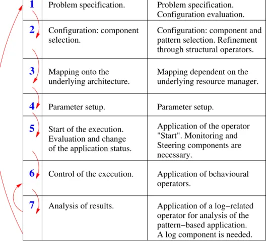
1.7 The software life-cycle of application development in PSEs (left column) and the mapping of the application of the pattern and operators model to that life-cycle (right column). . . . 22
2.1 Useful paradigms and techniques and their characteristics. . . . 27
3.1 Relating the used pattern definitions.. . . 54
3.2 The basic steps of the methodology. . . . 56
3.3 The Star pattern. . . . 58
3.4 The Pipeline pattern. . . . 59
3.5 The Connector pattern. . . . 59
3.6 The Ring pattern. . . . 60
3.7 The Adapter pattern [9]. . . . 61
3.8 The Facade design pattern [9]. Example: the "Facade” provides a unified in-terface for accessing domains in the Grid environment, redirecting the calls to services like "discover” and "execute”. . . . 61
3.9 The Proxy pattern [9]. . . . 62
3.10 Graphical representation of examples of Structural Pattern Templates (S-PTs).. 62
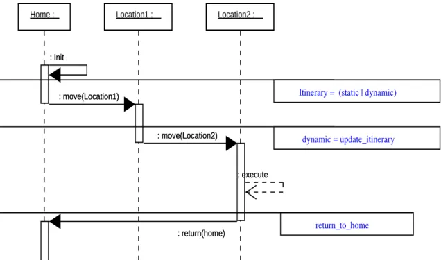
3.11 A Sequence diagram for the Mobile Agent/Itinerary pattern defining a possible itinerary for the component. . . . 66
3.13 Two Behavioural Pattern Templates, namely Client/Server and Observer B-PTs, applied to a Star PT. . . . 67 4.1 The creation of three S-PTs, namely a Star (“starPT”), a Facade (“facadePT”),
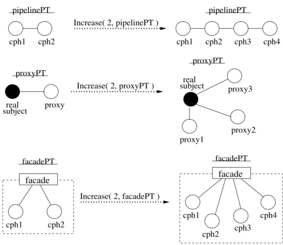
and an Adapter (“adapterPT”) . . . 86 4.2 Examples of the Reshape operator over a Pipeline and a Proxy Pattern Templates. 87 4.3 Examples of the Increase operator applied to Pipeline, Proxy, and Facade
Pat-tern S-PTs. . . . 89 4.4 Examples of the Decrease operator applied to Pipeline, Proxy, and Facade
Pat-tern S-PTs. . . . 90 4.5 Examples of the second application versions of the Increase and Decrease
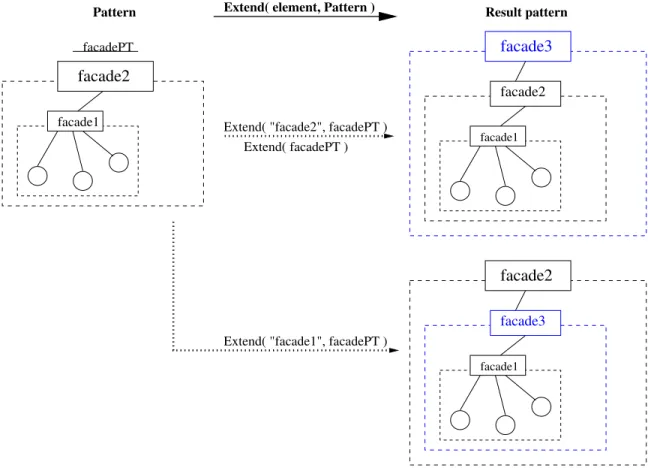
oper-ators upon a Pipeline S-PT. . . . 90 4.6 Examples of the “Extend( P )” operator over cases of the Proxy, Adapter, and
Facade Pattern Templates. . . . 91 4.7 Example of the “Extend( element, P )” operator over one Facade Template. . . . 92 4.8 Example of the “Extend( element, P )” operator over one case of Adapter Template. 93 4.9 Different ways of applying the “Extend( element, P )” operator to a Proxy
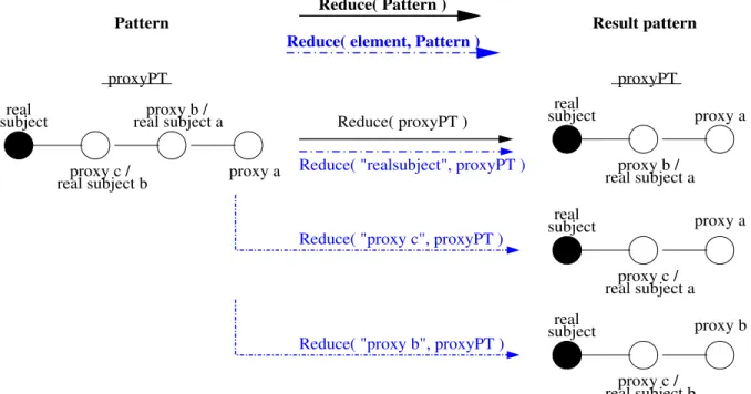
Tem-plate.. . . 94 4.10 Examples of the application of both versions of the Reduce operator to one Proxy
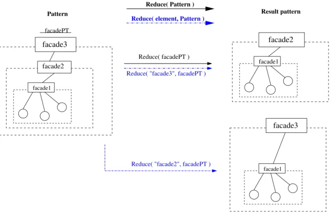
Template. . . . 95 4.11 Examples of both versions of the Reduce operator over one Facade Template. . . 96 4.12 Examples of both versions of the Reduce operator applied to an Adapter Template. 97 4.13 The pattern templates "ringPT” and "startPT” are grouped through the Group
operator, and the resulting aggregate is named "groupPT”. . . . 98 4.14 The group "groupPT” is dissolved through the Ungroup operator. . . . 99 4.15 Adding a extra pattern template to the aggregate "groupPT”. . . . 99 4.16 Merging of groups "group1PT” and "group2PT” through the Group operator,
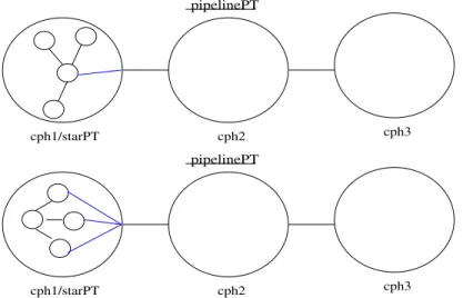
producing the aggregate "group1PT”. . . . 100 4.17 An example of a pipeline template with an embedded pattern (a star) in the
leftmost stage (“cph1”). This hierarchic pattern template is built through the Embed operator. . . . 100 4.18 Examples of possible connections between the embedded pattern and the
enclos-ing pattern. . . . 101 4.19 Extracting pattern “starPT” from within the first stage of the pattern
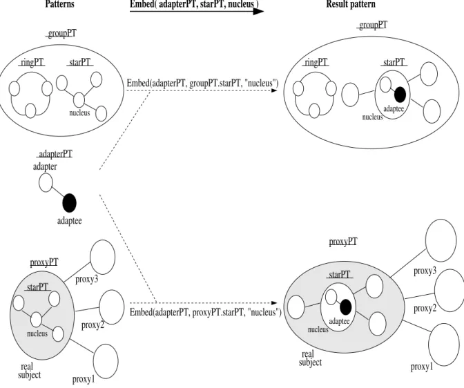
“pipelinePT”. . . . 102 4.20 Embedding an adapter template into a proxy template in the position of the
4.22 Embedding the same pattern template into two Hierarchical Pattern Templates. In both examples, the "adapterPT” is embedded in the "nucleus” of a "starPT”, but in one case (upper part of the Figure) this latter pattern is included in a group, whereas in the other, the "starPT” is embedded in the "realsubject” position of the "proxyPT”. . . . 104 4.23 Extracting a pattern template from a Hierarchical Pattern Template, namely a
starPT is removed from within the "realsubject” of a proxyPT, and the “real-subject” gets uninstantiated. . . . 105 4.24 Extracting a pattern template from a Hierarchical Pattern Template,
specifi-cally, the adapterPT is extracted from the "nucleus” of the starPT which is located in the position of the "real subject” in the proxyPT. Consequently, the “nucleus” of the starPT gets uninstantiated.. . . 105 4.25 Building a new similar PT to the ProxyPT but where a ringPT is embedded in
the "nucleus” of the starPT (instead of the adapterPT). . . . 107 4.26 Transforming an embedded pattern into another through the Reshape operator. 108 4.27 Applying the Extend and Increase operators in sequence to a Proxy PT. . . . . 108 4.28 Applying the Extend and Increase operators in sequence to a Facade PT. . . . . 110 4.29 Applying the two versions of the Reduce operator to the "proxyPT” template. . 111 4.30 Applying the two versions of the Reduce operator to the "facadePT” template. . 111 4.31 Applying the Increase and Decrease operators to a pipeline hierarchic pattern
that contains an embedded pattern in the first stage. . . . 113 4.32 Applying the Extend operator to a proxy hierarchic pattern that contains an
embedded pattern in the “realsubject” element. . . . 114 4.33 Applying the Reduce operators to a facade hierarchic pattern that contains an
embedded pattern in the outmost facade element (i.e. “facade2”). . . . 115 4.34 An example of a CO_OPN/2 object with its behaviour modelled through a
Petri-Net. . . . 116 4.35 An example of a synchronised call between two CO_OPN/2 objects. . . . 117 4.36 An example of a CO_OPN/2 context with two objects. . . . 118 4.37 Example of the Start and Terminate operators over a pipeline pattern instance.. 120 4.38 Example of the Stop and Resume operators applied to a pipeline instance. . . . 121 4.39 Example of the Repeat and TerminateRepeat operators applied to a pipeline
in-stance. . . . 123 4.40 Example of the Limit operator applied to a pipeline instance. . . . 124 4.41 Example of the Restart and TerminateRestart operators applied to a pipeline
instance. . . . 125 4.42 Example of the Log, TerminateLog, SeqLog, TermSeqLog, and ResumeLog
5.3 Applying a single Behavioural Pattern to all elements of a Structural Pattern forming a Regular SB-PT. . . . 140 5.4 Defining the behavioural role of one specific element within a pattern (and the
adding of other necessary behavioural annotations). Since that behavioural role pertains a different Behavioural Pattern than the one already applied to the pattern, the result is an Heterogeneous SB-PT. . . . 140 5.5 Replicating a SB-PT in two ways: a) considering it as a first class entity
(“facadeSB-PT”); b) acting only over the Structural Pattern Template included in the SB-PT (“facadeS-PT”). . . . 144 5.6 Augmenting the number of component-place holders of a SB-PT in two ways:
a) considering it as a first class entity (“facadeSB-PT”); b) acting only over the Structural Pattern Template included in the SB-PT (“facadeS-PT”). . . . 146 5.7 Extending two SB-PT in two ways: a) considering it as a first class entity
(“proxySB-PT”); b) acting only over the Structural Pattern Template included in the SB-PT (“facadeS-PT”). . . . 147 5.8 Applying the Reduce operator to a SB-PT. . . . 148 5.9 Modifying the behavioural annotations of a SB-PT considered as a first class
entity (“facadeSB-PT”). . . . 149 5.10 Instantiation of the component place-holder “cph1” of the pattern
“facade-CISP” to the “Resource management” component. . . . 150 5.11 Extending a Component Instantiated Structural Pattern, namely “facadeCISP” 151 5.12 Increasing a Component Instantiated Structural Pattern (“facadeCISP”) by
two component place-holders. . . . 152 5.13 Increasing a component instantiated Pipeline (“pipelineCISP) by two
compo-nent place-holders inserted after element "FFT”. . . . 152 5.14 Application of the Decrease operator. The first example (upper part of the
Fig-ure) presents a case of reducing the number of component place-holders from a Partial CISP, namely, a partially instantiated Facade. The second example shows the usage of the Decrease operator to eliminate a set of elements from a Partial CISP ( “pipelineCISP”) starting at a specific element, namely the "Gaussian” element. . . . 154 5.15 Elimination of one particular element of the “facadeCISP”, namely
“Scientific-tool”. . . . 154 5.16 Increasing a Regular FC-PI by one element, namely a pipeline pattern combined
with the Streaming Behavioural Pattern. . . . 157 5.17 Increasing an Heterogeneous PI by one element, namely a star pattern
5.18 Decreasing a partially instantiated Heterogeneous PI by two component place-holders. Although it was requested the deletion of three CPHs, only the two existing CPHs are deleted. All behavioural annotations pertaining to those
components are also eliminated. . . . 159
5.19 Decreasing two PIs by one element. On top, the element “FFT” is removed from the Regular PI “pipelinePI”. On bottom, the element “Newscenter” is removed from the Heterogeneous PI “starPI”. . . . 160
5.20 Applying the Extend operator to a PI (“adaptLegacyPI”). At the top, the struc-ture is augmented disregarding the applied Behavioural Pattern. At the bottom, the PI is operated as a Regular FCSB-PT which results in the automatic anno-tation of the new element with a role within the applied Behavioural Pattern. . 161
5.21 Applying the Reduce operator to a PI. . . . 162
5.22 Changing the behavioural annotations of two Regular PIs. . . . 163
5.23 Summary of the possible steps for reconfiguring a running application. . . . . 164
5.24 The dynamic reconfiguration of a Regular Pattern Instance representing a Grid service. . . . 167
5.25 Building a dynamic itinerary for an Agent . . . 167
5.26 Reconfiguring a Pattern Instance whose execution needs to be stopped.. . . 168
6.1 A generic architecture that supports the model based on Patterns and Operators. 171 6.2 The necessary steps to configure and execute an application using patterns and pattern operators. Please read the Figure starting from the bottom. . . . 173
6.3 Application of the Increase Structural Operator at development time and after step 4 in Figure 6.2, in order to instantiate application App5 as the last stage of the pipeline. . . . 175
6.4 Modifying the control dependencies within the pattern, after the application in Figure 6.3 is executing. . . . 176
6.5 The specific architecture, based on the Triana environment, which supports the patterns/operators model. The shaded elements in the upper layer are the result of the work presented in this dissertation. . . . 178
6.6 The Triana’s Graphical User Interface. . . . 181
6.7 A simplified vision of Triana’s distribution model. . . . 184
6.8 The inclusion of Patterns and Operators into the Triana Environment. . . . 186
6.9 The Triana’s Graphical User Interface. . . . 187
6.10 Iinitalisation of Pattern Template. . . . 187
6.11 Application of the Embed Structural Pattern to the Ring Pattern Template. . . 188
6.12 Instantiation of the DummyUnit component place-holder to the AccumStat Unit.189 6.13 A Ring pattern fully instantiated at the outmost level. . . . 190
6.15 General structural manipulation from a script defined in EBNF. The presented actions (nonterminal EBNF elements) may be interleaved and applied as many times as necessary. A terminal element defining the end of script processing is omitted for simplification reasons. . . . 191 6.16 Structural Operators. . . . 192 6.17 EBNF definition of the usage of the Embed Structural Operator from a script. . 192 6.18 EBNF definition of the names of the component place-holders within a Pattern
Template. . . . 192 6.19 EBNF graph for the “Instantiate_DummyUnit” nonterminal element in the
graph in Figure 6.15. . . . 193 6.20 EBNF graph for the “Create_and_Embed_Other_Patterns” nonterminal
ele-ment in the graph in Figure 6.15.. . . 194 6.21 EBNF graph for the “Create_Pattern” nonterminal element in the graph in
Figure 6.20. . . . 194 6.22 EBNF graph for the “Run _Structural _Script” nonterminal element in the
EBNF graph in Figure 6.20. . . . 195 6.23 EBNF graph for the “SetApplication _Parameter” nonterminal element in the
EBNF graph in Figure 6.22. . . . 195 6.24 The data and control flow connections in a (Hierarchical) Pattern Instance. . . 198 6.25 The parameter panel representing the Execution Operators and their
argu-ments. The Restart Operator is selected to launch the periodic execution every 10000 milliseconds. . . . 198 6.26 Application of the Terminate operator. . . . 199 6.27 Execution debug information generated upon application of the Terminate
op-erator to a pattern-based application ruled by the Restart opop-erator. . . . 199 6.28 EBNF graph for the Execution Operators. . . . 200 6.29 EBNF graph for the execution control of pattern-based applications. . . . 200 6.30 EBNF graph for explicit execution control including the usage of trigger nodes. 200 6.31 Activating a trigger node from a Pattern Instance’s parameter panel. . . . 201 6.32 Definition of a Pattern Instance. . . . 203 6.33 UML simplified description of some Triana classes. . . . 204 6.34 Simplified UML definition of the classes for creating and manipulating
Pat-tern Templates and Instances through Structural and Behavioural Operators, respectively. The definition includes a particular example of the Ring pattern template.. . . 205 6.35 The data and control flow connections in a (Hierarchical) Pattern Instance. . . 207 6.36 A Streaming (data-flow) Behavioural Pattern combined with a Pipeline
6.37 DRMAA mapping of the Start operator. . . . 210
6.38 DRMAA mapping of the Terminate operator. . . . 212
6.39 DRMAA mapping of the Stop operator. . . . 212
6.40 DRMAA mapping of the Resume operator. . . . 213
6.41 DRMAA mapping of the Repeat operator. . . . 214
6.42 DRMAA mapping of the Limit operator. . . . 215
7.1 The Centralised and Ring distributed systems topologies. . . . 221
7.2 The Hierarchical distributed systems topology ( c ) and its modelling through the Star Structural Pattern Template manipulated by Structural Operators. . . 223
7.3 The Decentralised topology.. . . 224
7.4 The hybrid Centralised+Ring topology, and its configuration by embedding a Ring Pattern Template into the nucleus of a Star Pattern Template.. . . 224
7.5 The hybrid Centralised+Centralised topology, and its configuration by the com-bination of the Star Structural Pattern and the Client/Server Behavioural Pattern.225 7.6 The hybrid Centralised+Decentralised topology. . . . 226
7.7 A PSE supporting the active steering of a Problem Solver. The arrows represent the flow of data. . . . 226
7.8 The Monitoring service is stopped and consequently the Steering interface also stops. The output data is not lost because it is being saved in the Database system.227 7.9 The initial Monitoring service is replaced with a more complex one (Monitoring and Statistics service), which is activated to continue the filtering of the output data. . . . 227
7.10 After the Problem Solver terminates its execution, data can be re-analysed.. . . 228
7.11 Identification of the Ring and Pipeline patterns in the PSE example. . . . 228
7.12 Identification of the Star, Adapter, and Proxy patterns in the PSE example. . . 229
7.13 Combination of the Ring pattern with the Producer/Consumer Behavioural Pat-tern, and the Pipeline pattern with the Streaming Behavioural Pattern. . . . . 230
7.14 Combination of: the Star SP with the Master/Slave Behavioural Pattern; the Adapter SP and the Service Adapter Behavioural Pattern; and the Proxy SP with the Client/Server Behavioural Pattern. . . . 231
7.15 Initial steps for building the PSE depicted in Figure 7.7. . . . 232
7.16 Final steps for building the PSE depicted in Figure 7.7. . . . 233
7.17 The final configuration for the PSE example.. . . 234
7.18 Applying the Terminate Behavioural Operator to replace the embedded “Moni-toringSv” Pattern Instance (PI) for the “Mon itStatSv” pattern. . . . 237
7.19 Applying the Start Behavioural Operator to the “Mon itStatSv” pattern to continue the execution. . . . 238
7.21 Resuming the execution of the embedded “SteeringInt” PI with the definition that the user “Pattern Controller” may manipulate this pattern with the In-crease/Decrease and Instantiate operators. . . . 239 7.22 Incrementing the number of proxies in the embedded “SteeringInt” providing
access to the “Steering Interface” to an extra (passive) user. . . . 240 7.23 New configuration for analysis of the PSE generated data formerly saved at the
Database system. . . . 242 7.24 A new component is directly connected to the Problem Solver. This
configura-tion is based on the one presented in Figure 7.17. . . . 243 7.25 Two Control Parallel skeletons: a) sequential and c) loop; and one Task Parallel
skeleton: b) pipeline. . . . 245 7.26 Modelling the farm Task Parallel skeleton. . . . 246 7.27 The “map” and “comp” Data Parallel skeletons. . . . 247 7.28 Modelling the reduce Data Parallel skeleton. . . . 248 7.29 A P3L example [151] composed of four DP tasks interacting according to the
composition of a farm TP and a pipeline TP. . . . 250 7.30 One case of modelling the P3L example in Figure 7.29 using the
Pattern/Oper-ator model. . . . 250 7.31 One possible reconfiguration of the pattern-based example in Figure 7.30 . . . 254 7.32 Two reconfiguration scenarios for the modelling presented in Figure 7.31. . . . 256 7.33 A P3L pipeline with two iterated stages. Results of stage 3 are fed back to stage
2 [151]. . . . 257 7.34 Modelling the P3L example in Figure 7.33 using the Pattern/Operator model. . 257 7.35 A simple example in the area of gravitational wave experiments. . . . 259 7.36 Initialisation of a Star PT. . . . 260 7.37 Addition of one satellite to a Star PT.. . . 260 7.38 A Star PT with three satellites and a Pipeline PT with three elements. . . . 261 7.39 Application of the Embed Structural Operator to the Star PT. . . . 261 7.40 Instantiation of a Unit. . . . 262 7.41 Final configuration. . . . 262 7.42 Execution results. . . . 263 7.43 Application of a script to a pattern template. . . . 264 7.44 Debug window showing the application of the Restart Behavioural operator. . . 265 7.45 A simple simulation of regular production of data by the gravitational wave
7.50 Applying the Repeat Behavioural Pattern for launching the execution ten con-secutive times.. . . 268 7.51 The animation is supported by a pipeline PT which is embedded in the nucleus
of the star PT. . . . 269 7.52 An example of a component place holder instantiation. . . . 270 7.53 A possible final configuration for the image processing of the “Galaxy
Forma-tion example”.. . . 271 7.54 Execution snapshot for the selected configuration. . . . 272 7.55 Parallel animation execution with different view points.. . . 272 7.56 Detail of the stage named Pipeline in the Ring PT from Figure 7.55 . . . 273 7.57 Configuration and execution of the Galaxy simulation example through the
script named "GalaxyExecCtrl". . . . 274 7.58 The ImgProjection pipeline.. . . 275 7.59 The ImgProcessing pipeline. . . . 276 7.60 The ImgAnalysis pipeline. . . . 276 7.61 The Star Structural Pattern supporting the configuration of the Galaxy example.276 7.62 Triggering the EnhContrast unit to consume the next 2D image. . . . 277 7.63 Triggering the EnhContrast and CountBlobs units. . . . 278 7.64 An execution step of the Galaxy example. . . . 279 7.65 The results at both satellites in the next execution step after the one presented
in Figure 7.64. . . . 280 7.66 The configuration of the ImgProjection pipeline for a step-by-step execution. . . 280 7.67 The Facade Structural Pattern Template.. . . 282 7.68 Configuration supporting the request of information to two sub-systems.. . . . 282 7.69 Two Pipeline Structural Patterns supporting the configuration of two
sub-systems for database access and output data analysis/processing. . . . 283 7.70 The parameter panel of DBExplore, a database inquire tool available in Triana.. 284 7.71 Application of the Extend Structural Operator to the Facade Structural Pattern. 284 7.72 Result configuration of the action in Figure 7.71. . . . 285 7.73 The innermost Facade acting as a subsystem of Facade1 in Figure 7.72. . . . . 286 7.74 An Adapter Structural pattern providing access to a simulation tool. The
Adapter pattern will replace Facade1. . . . 286 7.75 The configuration after the application of the Replace Structural Operator
de-scribed in Figure 7.74. . . . 287 7.76 Another possible configuration where the client application, the Requester,
List of Tables
1.1 Issues addressed by PSEs.. . . 7 3.1 Pattern Templates and Operator Summary. . . . 81 4.1 Applicability of Structural Operators to Topological and Non-topological
1
Introduction
Contents
1.1 Motivation . . . . 2
1.2 The Need of High-Level Abstractions for Grid Application Devel-opment . . . . 11
1.3 The Proposed Model . . . . 13
1.4 Contributions of the Thesis . . . . 23
1.5 Dissertation Outline . . . . 23
1.1
Motivation
In this section, the motivation for this work is presented, namely, we highlight the need of adequate programming abstractions to support the development of distributed ap-plications. Firstly, the main difficulties related to Grid programming are considered, followed by a discussion on the need of programming/software abstractions and en-vironments for Grid computing.
The goal of this work is subsequently presented, namely to contribute to a develop-ment environdevelop-ment based on high-level abstractions, with a specific focus on support for structured and flexible composition for application construction, reconfiguration, and execution control. To that extent, this chapter introduces the main characteristics of the proposed approach underlying the above goal, and which are further discussed throughout this thesis.
1.1.1
The Importance of Grid environments
Large-scale distributed applications have increased in importance in the last years as a result of the Internet expansion and economical globalisation. People communicate globally more than ever, discovering the benefits of distributed environments and, at the same time, continuously demanding better capabilities provided by those environ-ments. Therefore, there is a strong need for applications that reliably support large amounts of users independently from their location, support collaboration, span or-ganisations’ boundaries, and provide the user with adequate qualities of service. In this context, the growing importance of Grid environments results from their current and planned features for promising development for enabling such large-scale dis-tributed applications.
Grids are highly heterogeneous, complex, and dynamic distributed systems pro-viding large number of users the additional possibility of high computational power and access to large amounts of data [50,96]. Such facilities were not easily accessible or combinable before the Grid era. Nowadays, and through Grid environments, the user has, on one hand, access to a high number of very different resources such as high-performance computing and networks, storage systems, intelligent sensors, and many specific scientific instruments and systems; on the other hand, many of those resources are already accessed through standard services which aim to provide a common basis for application deployment.
different times.
Grid Applications
Over the years, the motivation to exploit Grid environments has been increasing, both in science and business domains. Nowadays, Grids are increasingly targeted at non-academic areas such as business applications in the domains of Life Sciences, Electronic Design, Financial services, and Aerospace and Film industries [197–199].
Initially, the Grid concept was mainly motivated by developments in the area of High-Performance Computing and was aimed to support computational scientists on their efforts to enable larger engineering and scientific applications. Examples, among others, are projects such as the DataGrid [57] and MyGrid [56] that provide scientific platforms that simplify the application development in specialised domains such as High-Energy Physics, Astrophysics, Biology, Earth observation, etc.
Present and future Grid applications in science and engineering aspire to hide the complexity of the underlying execution platforms and integrating both specific and general purpose tools and instruments without hindering the possibility of choosing the best solutions for each kind of application domain.
Grid Architectures
Major Grid platforms like Globus [11], Legion [52], and UNICORE [53] try to provide reliable and transparent testbeds for the users to submit jobs. After an initial authenti-cation process, users may submit their jobs to resource managers which control differ-ent hardware and software resources, across their administrative domains.
The need for standardisation has led to an ongoing effort to make Grids’ distinct features compliant to Web Services resulting, for example, on the development of the Open Grid Service Architecture (OGSA)[48] specification. These efforts include the ex-tension of Web Services towards Grid Services, in order to have a simplified way to both access and combine different types of Grid resources. Advances on Grid services have been extensively discussed in the Open Grid Forum (OGF) (former Global Grid Forum (GGF)) with the intent of the pervasive adoption of Grid computing both for research and industry. [17].
1.1.2
Difficulties of Grid Application Development
The difficulties of Grid application development occur at different levels, namely appli-cation level, development/programming level, andsystem level(which include middleware and system architecture layers).
specification/characteristics of an application relate to the system organisation, its distributed architecture and the corresponding software and hardware re-sources; a suitable compromise must be sought between the required level of transparency and the degree of user control over the execution environment. Of course, this is critically dependent on user and application profiles. It may also happen that the levels of transparency and user control may be required to adapt, depending on the evolution of the computations. As an example, consider a sit-uation where adequate Quality of Service must be satisfied by the system: if the parameters defining the quality of service reach unacceptable values, the user may want to have an active role upon application (and system) reconfiguration. It is also difficult to understand how computation and data access application characteristics may affect the efficient usage of the allocated Grid resources, thus making it extremely difficult or even impossible for the user or application devel-oper to make decisions concerning the appropriate mapping between the needed and available resources.
The above difficulties can be overcome by providing: 1. adequate development/programming environments;
2. adequate middleware/system support that contribute to ease the mappings from the logical application characteristics to the allocated system resources, and also that allow their dynamic reconfiguration.
Development/Programming Level Difficulties At this level, the main difficulties are due to the complexity of applications (in science and engineering, but also in business) built out of a large diversity of heterogeneous components (some of which can be legacy codes of high internal complexity), which are based on dif-ferent programming and computation models, and that may require distinct (and sometimes incompatible) execution support environments.
Due to the above, adequate abstractions should be provided in order to support clear separation of concerns, in the following dimensions:
• regarding the logical component specification and its execution
environ-ment, allowing a clear separation between the logical application organi-sation and its system level deployment;
• regarding the component individual interfaces and how they are
intercon-nected in order to build a global application structure;
• regarding individual component behaviour and how global application
System Level Difficulties The difficulties at system level, including middleware and system architecture layers, are related to the issues of how distributed operat-ing systems for Grid platforms will be capable of handloperat-ing scalability (physical, number of users, hardware/software resources), heterogeneity (in computation, storage and communication physical resources, and also in the logical or soft-ware resources), dynamic nature (in terms of failure; of unpredictable variation in system behaviour; and of modifications in hardware/software components and services), and the span of system administrative domains, coupled with the critical issue of security.
In most existing Grid systems, the user interface is too low-level and mostly dedi-cated to job submission. It is still assumed that the application developers should have a solid knowledge of the interface details for resource allocation, and their proper or-chestration with data location and file management. Consequently, adequate facilities for resource composition and coordination are still lacking in those systems.
In order to solve such difficulties, the integration of high-level abstractions, for example based on components and workflow management tools into Grid environ-ments has proven extremely useful for simplifying Grid application development. Component-based models encapsulate different kinds of resources and with different granularities, thus providing a clearer and simpler interface for their access. Never-theless, the composition of components supporting adequate data and control flows is a difficult task, moreover considering the large-scale, dynamic, and heterogeneous characteristics of Grid environments.
Considering such difficulties, workflow systems for Grid environments aim at im-proving application development support (e.g. [4, 23, 206]). Concerning its structur-ing and composition, workflow systems based on components support specific data and control flow mechanisms for defining data paths and enacting component execu-tion. Usually a straightforward Graphical User Interface for component composition is available, but this is not mandatory, an alternative being a textual workflow language. In the lower layers, support for the workflow execution exist.
Workflow systems enable important functionalities:
• component reuse and composition;
• adequate User Interfaces (UI) for application specification;
• adequate interfaces and mechanisms for their integration into the enclosing
en-vironment, flexibility to incorporate script-based control languages, and flexible interfaces to the underlying resource management layers and execution support systems, including the Grid;
• managing the entire life cycle of application, including specification, deployment
1.1.3
Problem Solving Environments (PSEs)
In our work, we are interested in approaches based on Problem Solving Environments (PSEs). PSEs are integrated environments which help scientists and engineers to solve problems in their specific domains.PSEsintegrate specific models (like models for rep-resenting the human body, or models to represent the wind flows on the atmosphere), andgeneric or specific toolsto evaluate or control those models. An example of a generic tool is a 3D visualization front-end which may be used in both a medicalPSE and a weather prediction PSE. However, a medical PSE may integrate a specific tool like a controller for a medical robot, whereas a weather forecastPSEmay integrate a different specific tool like a mathematical engine for wind and temperature analysis.
This is an area of intensive research, requiring expertise from very different do-mains in science and engineering, fitting what is commonly designated as computa-tional science and engineering [90,91]. PSEs are particularly helpful for complex appli-cations where large number of users may interact at an abstract level, namely using the languages and models of the specific scientific domains, as well as adequate user in-terfaces. Hence, PSEsrequire support platforms capable of combining heterogeneous distributed computational components, and of transparently supporting the complex interactions between the components and the users.
Traditionally, PSEs have been providing specific support to the development and execution of experiments in science and engineering. In general, the user interface is a virtual workbench that tries to simulate a real laboratory and which is accessed using a high-level language, specific to the problem domain.
The main goal of the PSE developers is to combine the best of two worlds: to provide transparent access to the specific software resources required by applications, and to better exploit the available distributed computational capabilities. Since a large number of traditional PSEs for different application areas include common resources or tools with similar functionalities, middleware platforms try to capture and provide those similarities.
Middleware platforms for PSEs [90, 112–114] offer the necessary generic support to build application specific PSEs, thus simplifying the developers’ tasks. Those plat-forms provide facilities for a broad class of applications in the areas of Environmental Engineering, Weather control, Chemistry and Physics Engineering, Mechanical Engi-neering, among others.
Furthermore, those generic platforms follow the principles of the component paradigm [27, 100], what is important for reusing and composing the resources to as-semble a new particular PSE. An important evolution of this component structuring is the need to add support for dynamic operation, i.e. PSEs with configurations that may evolve in time and allowing users to control those changes directly.
Environments Problems
High performance requirements Massive data processing
PSE Highly heterogeneous tools
Flow dependencies Reliability
Security
Complex interactive Tool synchronisation
environments Consistency
Cooperative work
Dynamic environments Dynamic reconfiguration
Table 1.1: Issues addressed by PSEs.
the following we discuss a number of issues addressed by PSEs as illustrated in ta-ble 1.1:
• Many scientific applications usually have high-performance requirements which
use complex mathematical models requiring the support of parallel processing systems.
• Many applications produce large amounts of data. As such, PSEs have to give
support to the storing, management, and transmission of huge bulks of data.
• The computational components are heterogeneous, both in their hardware and
software requirements, as well as in their computational models (e.g. sequential, concurrent, event-driven).
• In other situations, e.g. like code coupling simulations, PSEsmay have to
inte-grate models from different scientific areas (like mathematics, physics, biology, geography), so that expert users from different areas may communicate, or even use tools from another area without having to know the intricacies of the scien-tific language of that area.
• In an integrated PSE, tools may exhibit mutual dependencies. For example, if
the execution of two cooperating tools involves frequent interactions (e.g on the throughput of the flow of data), their mappings to real processors should take such dependencies into account.
• Reliability may also be mandatory. Several applications are critical systems (e.g.
medical systems) which require continuous execution with fault-tolerance.
• Many distributedPSEshave to address security issues.
• Additionally,PSEsshow characteristics common to complex interactive
may critically depend on the correct synchronisation of a set of heterogeneous tools, each one showing specific hardware and performance requirements. Considering another example, a set of users may want to cooperate on the steer-ing of a scientific experiment (i.e. control of the parameters of the experiment at run-time, so that different execution scenarios can be analysed and compared). The system will have to support some coordination, so that parameter steering by the users is consistently applied and perceived by the concurrent users (ob-servers).
• Finally, futurePSEs aim at solving additional kinds of problems not present in
current PSEs, such as problems related to dynamic reconfiguration and adapt-ability. For a comprehensive discussion on future trends of PSEs, please refer to [38].
The Cycle of Activities of a Typical Problem Solving Environment
Control Component Steering
Visualization
Configuration
Visualization Component Distributed Simulation Component
Solver
Solver
Figure 1.1: A typical logical architecture for a distributed/parallel PSE consisting of three components – a distributed simulator, a visualisation and a control component.
1. Problem specification using an application specific model (for instance, an algo-rithm for parallel and distributed simulation).
2. Configuration of the logical architecture of the PSE, achieved by component se-lection (for example, components that represent the simulation, components for visualisation, and components for execution control), and their associated sup-port tools.
3. Component activation and mapping onto an underlying architecture.
4. Initial definition and setup of the parameters of the application components, de-pending on the selected type of the application model (for example, a simulation may be executed under different models, each one needing specific parameters). 5. Start of the execution with specification of observation and control functionalities
(for example, start of the simulation, with monitoring and steering). 6. Interactive control of the execution.
7. Analysis of the intermediate or final results.
The above steps may be repeated cyclically until the desired final results are ob-tained. Depending on the specified modes of operation, the final results may have to be logged into files for post-mortem processing or passed to other tools or subsystems. For example, in the simulation example, in steering mode, the intermediate results are displayed on-line, and the user can dynamically modify the simulation parameters. In general, the experimentation process may lead the application developer to go back to step 1 and repeat the above cycle with different approaches for problem specification for each step.
In order to ease the above identified difficulties at the application level (sec-tion 1.1.2), long-term efforts have been trying to improve the func(sec-tionalities offered by PSEs[18, 93]. Current state-of-the-art PSEs are complete, integrated computing envi-ronments for composing, compiling, and running applications in a specific application domain, trying to provide all the computational facilities necessary to solve a target class of problems.
For example, following these ideas, several ongoing projects have been trying to promote high-level paradigms for application development, based on the workflow and thecomponentconcepts [1, 15–17]. Component based models provide an effective way to develop applications from a range of different software libraries, and possibly wrapped legacy codes. Components can vary in complexity and granularity – ranging from complete applications to specialised sub-routines. The associate environments provide interfaces to specify the manipulation of components, e.g. the selection of components from a repository and their combination through a visual editor.
Features Lacking in PSEs, even for Grid Development
Some PSEs already support the deployment of applications into distributed Grid plat-forms (e.g. Triana [201]). However, although the user is already able to run component-based applications in a Grid, the support of structured and systematic ways of reusing components is still limited. Most state-of-the-art component-based PSEs support lim-ited structured component composition, and have limitations regarding the support for significant changes in the structure and flow dependencies.
Many PSEs allow the user to specify direct connections between components, for example through channels and ports, but usually still lack full support on important aspects like:
• explicit support for defining and composing new (typical) structures for
compo-nent interconnection that may be subsequently reused in similar problems. Those (reusable) structures should be manipulable from component repositories with operations like save, recovering, and searching;
• facilities for manipulation of such structures and topologies as templates
(par-tially instantiated). Those templates should be able to be refined and instantiated (either at development and execution times), by applying specific commands or operators;
• existence of adequate, flexible, and architecture neutral interfacing to the resource
1.2
The Need of High-Level Abstractions for Grid
Appli-cation Development
1.2.1
Components and Services
Due to the complexity of Grid environments, several projects have been developing programming models based on encapsulated units such as components and Web/-Grid services [20, 59, 63–67, 114]. Although such models do simplify the development process by providing units that can be composed and reused, the management of de-pendencies and coordination between those units is still a difficult task. Moreover, it is desirable to reuse useful components’ interdependencies as a way to support less experienced users and to improve the development process. Additionally, Grid appli-cations’ execution control and dynamic reconfiguration are still open research subjects.
1.2.2
Skeletons and Design Patterns
Similarly to what has happened to general purpose programming languages and mod-els, distributed Grid application development might benefit from the manipulation of higher-level abstractions, namely design patterns [9], as first class entities. Currently, patterns are not just a modeling abstraction anymore, but have also been included into development tools and in languages, as first class entities [61, 62].
APatternencodes a commonly recurring theme in service or component composi-tion. It allows good practice to be identified, and shared across application domains. A pattern is generally defined in an application independent manner, and used to encode characteristic useful behaviours. Patterns are particularly useful for configuring and specifying systems that are composed of independent sub-systems. Patterns are aimed at capturing some common and generic attributes of a system – which may be further refined (eventually) to lead to an implementation.
The above concepts can meet important requirements for Grid applications, which generally need to operate in dynamic environments. Furthermore, users of a Grid infrastructure usually have different abilities, and less experienced users may find it difficult to identify useful architectural models for interconnecting components, or ad-equate coordination behaviours. As such, the availability of recurring patterns allows the selection of the most adequate solutions, potentially reducing both applications’ development complexity and effort. Moreover, the introduction of patterns as first class entities allows the manipulation of a pattern (and its elements) as a single entity from design time to execution time, increasing re-usability and maintenance. Accord-ingly, pattern-based concepts may become units of both execution control and dynamic configuration.
pat-terns may be defined, stored and reused independently of the individual components. Tools like the ones mentioned in [54, 55] provide a pattern-based approach for com-ponent composition – for example, theObjectAssembler[55] visual development envi-ronment provides a catalogue of patterns for connecting JavaBeans components [104]. Similarly, thePacosuite[54] tool supports component composition throughcomposition patternswhich define component interactions. Nevertheless, the patterns in those sys-tems are neither manipulable as execution units nor dynamic reconfiguration units.
The Grid community has already recognised the importance of patterns [47] as a way to re-use expert knowledge, but those still have limitations and are generally still not available as a programming paradigm for the Grid (or integrated in Grid software development environments). Works on skeletonsfor Grid computing [195, 196] repre-sent a related approach towards reusability of expertise within Grid Environments. Specifically, skeletons are programming abstractions (most often inherited from func-tional programming and parallel-processing systems) that are sometimes amenable to optimised implementations of typical parallel algorithms. Nevertheless, the available skeletons present on those Grid Environments are not kept as first-order abstractions throughout a Grid application’s life cycle.
1.2.3
The Main Goal of this Work
Motivated by the above considerations, we argue in favor of an approach which aims at providing patterns to Grid environments in two main dimensions, namely struc-tural and behavioural. Such separation of concerns contribute to increase flexibility on pattern-based application configuration.
The aim of this work is to contribute to simplifying the development of distributed applications, namely mapped to Grid environments, by providing a novel way to com-pose and manipulate their components. Specifically, the goal is to enhance the appli-cation development cycle supported by Problem Solving Environments by providing:
• Reuse of typical application configurations.
• Structured support for constructing new configurations and controlling their
ex-ecution.
• A systematic methodology applicable in all the stages of the application
develop-ment cycle, from application specification to execution and reconfiguration con-trol.
at the behavioural/coordination level. The focus was then to try to capture those com-mon interaction patterns into well identified abstractions. These are made available for reuse through an uniform and extensible model which allows the user to combine and control those abstractions in a structured and systematic way. A first overview of our approach, which we designate asmodel, is described in the following section.
1.3
The Proposed Model
Themodelpresented in this dissertation electspatternsas the main abstractions that are kept asfirst class entities during the entire application development cycle. In this way, patterns can be manipulated either at design, execution, and reconfiguration times. That is, patterns are manipulable units for configuration, execution control and recon-figuration actions.
In the model, application configurations result from the composition of patterns (e.g forming different topologies and hierarchies) and may also be changed through pattern replacement or refinement. During execution time, individual control of pat-terns is also possible. Moreover, and with proper execution control, dynamic reconfig-uration may also be achieved. All these actions for pattern manipulation are performed through a variety ofOperatorsboth for design and execution times where all operators act upon patterns in a uniform way in all phases of the development process and for the different manipulable patterns.
Patterns and operators are used to support the specification and manipulation of the application configuration as composition of patterns, and these can be individually manipulated through adequate operators. Additionally, the distinction between two main categories, namely structural and behavioural, both for patterns and operators, provides the model with flexibility on application configuration, reconfiguration, and control. A pattern from one category (structural or behavioural) may be combined with different patterns from the other category, and also structural patterns may be manipulated independently from the associated behavioural patterns, and vice-versa. This is quite important for application development, as shown in Chapter 7 concerning the assessment of the model.
Furthermore, the persistence of patterns and their manipulation through opera-tors throughout the application development cycle promotes an uniform view of the model. Finally, the model promotes a methodology which on one hand may guide the user, and on the other hand may be (totally or partially) automated through scripts.
The following sub-sections describe structural and behavioural patterns and the methodology proposed.
1.3.1
Structural and Behavioural Patterns
combining components within a given application domain, as well as of reusing them across several applications. Examples of Structural Patterns are:
Pipeline: e.g. the detection of waves in a Cosmology application as the first stage, its analysis/processing through subsequent stages, and visualisation of results in the final stage;
Star: commonly underlying the Master/Slave processing in parallel applications where the nucleus, i.e. the Master, divides a problem into independent sub-problems and sends these requests to be processed by the satellites, i.e. the slaves; Facade: common in portal technologies for Web Services, which hides the access to several distinct services (or tools, instruments, etc.) under a simplified interface. Proxy: which usually supports the access to Grid services (through a proxy or
gate-keeper).
Structural Patterns are represented in our model throughTemplateswhose elements can be instantiated to executable entities (e.g tools, services, etc.) or to other Structural Patterns.
Behavioural Patterns, in turn, define interaction constraints, namely they rule the data and control flow dependencies among a set of components. Examples of Be-havioural Patterns are:
Client/Server: commonly present in distributed services; Producer/Consumer: common in workflow systems;
Itinerary: used in mobile Agent systems, where an Agent moves in order to accom-plish a task, leaving behind a chain of forward pointers keeping track of the Agent’s location.
Provided the above two categories of design patterns, configurations are built by selecting the Structural Patterns that best represent the connectivity between the appli-cations’ elements, and by applying upon those the appropriate Behavioural Patterns. The most adequate combinations of Behavioural and Structural patterns result from the users’ knowledge on the application needs and on the capabilities of the underly-ing support infrastructure.
Examples of Patterns in One Particular PSE
Steering Interface Service
Monitoring Selected data Output data
Input data
Database System Problem
Solver
Figure 1.2: A generic PSE.
As illustrated in Figure 1.2, basic components of this PSE are aProblem Solver(e.g. a scientific tool) that generates data to both aDatabaseand aMonitoring Servicefor data storage and filtering, respectively. Moreover, the data compiled by the latter service is fed into aSteering Interfacewhich shows relevant data to users interested in controlling some parameters of theProblem Solver.
Steering Interface
Database System Monitoring
Service
Proxy
Proxy Real Subject
(Steering Interface)
server
clients
{Proxy Strutural Pattern + Client/ServerBP}
Adapter
Adaptee
{Adapter S. Pattern + ServiceAdapterBP}
(Monitoring legacy code)
{Star S. Pattern + Master/SlaveBP}
Database (master)
Database
(slave) Database
(slave)
Database Database (slave) (slave) Selected data Output data
Input data
Problem Solver
{Pipeline Structural Pattern + StreamingBP}
{Ring Structural Pattern + StreamingBP}
Figure 1.3:Example of the identification of Structural and Behavioural Patterns in a PSE Figure 1.3 presents several identifiable configurations and how they are supported by correspondingStructural Patterns. The principal ones are:
a) aRing, establishing the necessary connections between theProblem Solver, the Mon-itoring Service, theSteering Interface, and this one back to theProblem Solver;
b) a two-stagePipelineconnecting theProblem Solverand theDatabase System.