~
albrasci
o s~ i oçO::J luso.b';llollc!IrO pe'o o ~ l,m;II" ;o COtll.a Inc6ndoo- u
c
-UNIVERSIDAD E DE CO IMDRA
ISBN 978-972-96524-9-3
I
1111111111
2° CILASCI - Congresso
Ibero-Lati
no-Americano sobre Segurança Contra
Incêndio
2° CILASCI - Congreso
Ibero-Lati
no-Americano en Seguridad Contra Incendio
Coimbra - Portugal
29 de Maio a 1 de Junho de 2013
João Paulo Correia Rodrigues
Departamento de Engenharia Civil da Faculdade de Ciências e Tecnologia da Universidade de Coimbra· Portugal
Ricardo Fakury
Departamento de Engenharia de Estruturas da Escola de Engenharia da Universidade Federal de Minas Gerais· Brasil
Rosaria Ono
Faculdade de Arquitetura e Urbanismo da Universidade de S. Paulo - Brasil
Jorge Munaiar Neto
2"d CILASCI
-
Ibero-Latin-American COl1gress on Fire Safety Engineering Coimbra,
Porlugol,
29'"
Moy
lo r'
JUl1e, 2013
EXPERIMENTAL INVESTIGATION ON THE PERFORMANCE OF
PARTIALLY ENCASEO BEAMS AT ELEVATEO ANO ROOM
TEMPERATURE
Paulo A, G, Piloto' Professor
IDMEC, IPB· Polytechnic Institute of Bragança, Portugal
Carlos Gonçalves Master student -Polytechnic [nstitute of Bragança, Portugal
Ana B, R, Gavilán
Professor
USAL • University of Sa[amanca, Spain
Luisa Barreira
ProfessorfTechnician LERM,
[PB-Po[ytechnic [nstitute of Bragança, Portugal
Luis M. R. Mesquita Professor
[PB - Po[ytechnic [nstitute of
Bragança, Portugal
Keywords: Partially Encased Beams; E[evated temperature, Experimenta[ tests, Bending
resistance.
1.INTRODUCTION
Partially Encased Beams (PEB) are composite stee[ and concrete e[ements Ihal presenl severa[ advanlages wilh respecl lo bare slee[ beams. They are usually buil! wilh hol rolled seclions wilh
encased concrete between flanges. There are different design solutions, considering the
arrangemenl of [ongiludina[ reinforcemenl of concrele, slirrup configuralion and material
strength. The reinforced concrete between flanges is responsible for increasing fire resistance,
[oad bearing and sliflness, wilhoul en[arging lhe overall size of bare slee[ cross seclion. Fire design, according lo European slandard EN1994-1-2 [1], is valid for composile beams, based on labu[aled melhods (considering simp[e supporting condilions and standard fire exposure) based on prescriplive geomelry lo a certain fire rating (lime domain). The simp[e ca[cu[alion melhod may a[so be applied lo PEB, using fire resislance on [oad domain, assuming no
mechanical resistance af the reinforced concrete slab (considering simple supporting conditions
and standard healing from Ihree sides). The eltecl of fire on lhe maleria[ characlerislics is laken inlo accounl, eilher by reducing lhe dimensions of lhe parts or by reducing lhe characlerislic mechanica[ properties of maleria[s.
Autor corrcspomlcnlc - iDMEC, Dcpanmcnt or Applicd Mcchanics, Polytcchnic Institulc or Bragança. Campus Santa Apolónia, ap. 1134 .. 5301-857
Paulo A. G. Piloto, Ana B. R. Gavilán, Luís M. R. Mesquita, Carlos Gonçalves, Luisa Barreira
Partially Encased Seams (PES) and Columns (PEC) have been widely tested at room temperature, but only a small number of experiments under fire and elevated temperature condltions have been reported. Kindmean et aI. [2J, perfonned thirteen tests on PES with and without concrete slabs, showing the importance of the reinforced concrete between fianges in detennining the ultimate bending moment. Hosser et aI. [3J, carried oul four experimental lests on simply supported composite PES, connected to reinforced concrele slabs, under fire conditions. Temperature changes were registered at different localions, including the PES cross section. Aulhors concluded that the effective width of lhe slab depends on the transversal longitudinal shear reinforcement. Lindner and Budassis [4J, tested lateral instability aI room temperature using twenty two full-scale PES with two different steel sections under Ihree-point bendlng test. A new design proposal for lateral lorsional buckling was proposed, taking into consideration lhe torsional sliffness of concrete. Maquoi et aI. [5J, improved and implemented the knowledge on lateral lorsional buckling of beams, including PES, and prepared design rules Ihat were not salisfactorily covered by the existing standards. Assi et aI. [6J, developed a theoretical and experimental study on lhe ultimate momenl capacity of PES, perfonning twelve bending tests on specimens with four differenl IPE cross sections, to investigate the contribution of different types of concrete. Makamura et aI. [7], tesled three partially encased girders with longitudinal rebars and transversal rebars (welded
f!N)
and not welded (NW) to fianges}. The bending strength of lhe partially encased girder was almost two times higher than conventional bare steel girders. Authors concluded that lhe specimen with rebar not welded (NW) to fianges presented a decrease of 15 % for maximum load bearing when compared to the welded rebar (W) specimen. More recently, Kodaira et aI. [8J, decided to determine fire resistance of eight PEB, with and without concrete slabs. Authors demonstrated that reinforcement is effective during fire. In 2008, Elghazouli and Treadway [9J, performed len full scale tests on PEB. Theexperimental analysis was focused on inelastic performance, considering major and minor-axis
bending tests. Authors discussed several parameters related with the capacity and ductility with relevance to design and assessment procedures. Nardin and EI Debs [10J, studied lhe static behaviour of three composite PEB under flexural loading at room temperature, testing some alternative positions for shear sluds, using one type of mono-symmetric steel section. Experimental results confinned Ihat studs are responsible for lhe composite action and increase bending resistance, especially when the studs are vertically welded on the botlom fiange. A. Correia and João P. Rodrigues [11J, studied lhe effect of load levei and Ihennal elongation restraint on PEC, built with two different cross sections, under fire condilions. They concluded that the surrounding stiffness had a major influence on fire element behaviour for lower load leveis. The increasing of the surrounding stiffness was responsible for reducing criticai time. Criticai time remained practically unchanged for higher load leveis. Recently, Paulo Piloto et ai [12], lested fifteen PEB under fire conditions (small series) using three-point bending test lo detennine fire resistance. Results revealed lhe dependence of fire resistance on load leveI. Particular emphasis was given to the criticai temperature on lhe composite section.
The experimental tests presented in this paper aim to analyse the bending perfonnance of partially encased beams using four point bending tesl set-up, heated from two sides (top and botlom flanges), after stabilizing temperature levei (200, 400 and 600 ·C). The bending resistance of PEB is also compared with bare steel beams at roam temperature. Two different beam lengths were considered (medium and large series), using one cross seclion Iype
Experimental investigation on the performance of partially eneased beams aI elevated and
roam temperature
(IPE100) with !WO differenl shear eonditions be!ween stirrups and the web of the profile (W-welded and NW- nol (W-welded).
2. EXPERIMENTAL PROGRAMME
Twenty seven specimens were tested, divided into ten series. Two ar three tests were
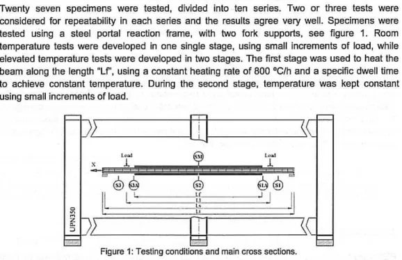
considered for repealability in each series and the results agree very well. Specimens were tested using a steel portal reaclion frame, wilh !wo fork supports, see figure 1. Roam temperature lests were developed in one single stage, using small incremenls of load, while elevated temperature lests were developed in !wo stages. The first stage was used to heat the beam along the length "Lf', using a constant heating rate of 800 ·C/h and a specific dwell time to achieve constant lemperature. During the second stage, temperature was kept constant using small increments of load.
=j-/ JL;Y '---~~~~---:rn'-l
i I--_-_-_-_-_~~~~\C
,__j=
L"",! 1.., .. 1
x
1
1
@0
@
0@
II
I '
Ü
~
J
JI
l~
~
K_
~
c::::::=
Figure 1: Testing conditions and main cross sections.
Tests developed at elevated temperature used electro-ceramic resistances to increase and
sustain temperature during loading. Five different cross sections were defined to measure
temperature (S1, S1A, S2, S3A and S3), and one eross seetion (SM) was defined to measure strain, displacements (vertical ZG, lateral Y G) and cross section rotation eG.
2.1 Specimens
PEB were prepared by filling the space be!ween the flanges of a steel IPE100 profile, using reinforced concrete (RC). Partially encased sections achieve higher fire resistance when compared to bare steel sections. The increase in fire resistance is due to the encased material,
reducing the exposed steel surface area, introducing concrete which has a low thermal
Paulo A. G. Piloto, Aoa B. R. Gavilán, Luís M. R. Mesquita, Carlos Gonçalves, Luisa Barreira
" . + . ; .~ . :. ~ I
I
',;"J
F":,cii,_,'=
..
_
",,::'=-'
,
o
o:i:i
i
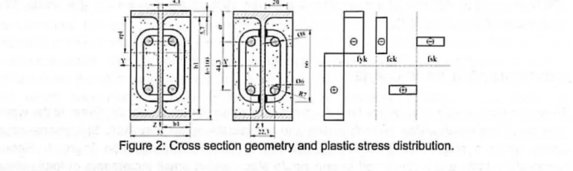
Figure 2: Cross section geometry and plastic stress distribution.
PEB were made of IPE100 with steel S275 JR, using encased concrete wilh siliceous aggregales. Four longiludinal steel 8500 rebar were applied with diameler of 8 mm. Slirrups were designed with 8500 rebar with a diameter of 6 mm, spaced every 167 mm. Stirrups were also partially welded to the longitudinal steel reinforcement, as represented in figure 2. The plastic neulral axis is referred lo "epl", reinforced concrele block dimensions are represented by "b1" and "h1", while "er" represents the relalive position of reinforcemenl. The plaslic momenl was calculaled using characterislic values for material properties, assuming certain hypolheses based on slress field, see figure 2 and eqs. 1-2, [4].
Mp/ =
JV,."" I,*- 2.I"J",,(
O.5/i,- e,., )'
/2 +f ...
2.b,.epl (O.5/i, - 0.5ep /)+2.A,.(/"
-
f ..
)(/i -2.e, ) (1)AI pllJ "" W",.".J;i k)6 -
2.1"
k ,01 ... ( 0.51'1 -epl ) ~/2
+ f .. .kdl ·2.h,..J!pI (O.s /~ -o.Se", )
+ 2.A,. .(J".ks(l -fd; kdJ )(h -2.c,) (2)2.2 Instrumentation
PE8 were prepared to be tesled at roam lemperature, measuring strain in central section (SM), over steel flange and web, in hot rolled seclion WS and SM-FS) and over concrele (SM-RS1 and SM-RS2). Whereas perfect bond was considered between concrete and reinforcement, concrete strain was measured on sleel reinforcement; for the lalter measurement, rebars were machined 1 mm in depth and 15 mm in lenglh, in respecl lo lhe dimensions of lhe eleclrical slrain gauge. Five strain gauges (H8M reference 1-LY11-6/120) were used. Ali slrain gauges were prolecled wilh gloss (Vishay reference M-coat A) and special viscous putty (HBM reference Ak22) against moislure, waler and mechanical damage. PEB were also prepared lo be lesled ai elevaled lemperalures, using lhermocouples lype K posilioned in five seclions along lhe lenglh of lhe beam. Therrnocouples were posilioned in place, using lhe spot welding machine. For the concrele lemperature measurements, positions Si-IC and Si-OC (nor represented), lherrnocouples were welded to a small steel washer, wrapped in concrete.
2.3 Materiais
Each steel material was characterized according to international standards [14] for hol rolled and cold forrned steel. Three samples were collected from lhe web of steel hot rolled profile and two more samples were collected from steel reinforcemenl. The average value for the elastic
Experimenta! investigation on the performance of partially encased beams at e!evated and
room temperature
modulus of the sleel profile was 197.9 GPa and lhe average values for lhe ReH- upper yield slrenglh (fyk) was 302 MPa. The values for lhe cold formed sleel (reinforcemenl) were respectively 203 GPa and 531 MPa.
Concrele was made wilh Portland cement, sand and silieeous aggregates. The concrele mixture was prepared for one cubic meler of concrele wilh sand mass equal lo 1322.7 [kg], aggregate mass equal to 451.1 [kg], water equal lo 198 [I] and cemenl equal lo 466.7 [kg]. The ralio
water/cemenl was 45 %. Aggregales were characterized by the sieving melhod and lesled
aceording to European slandard [15] lo delermine partiele size dimensiono Due lo lhe small size of the sleel seclion and considering lhe space available lo cover lhe stirrups, lhe concrele used small-sized aggregates. The percenlage of aggregales wilh diamelers between 4-6 mm was 90%, while lhe percenlage of sand wilh diamelers between 0.063-0.5 mm was 80%. The aggregate dimensions limil lhe value of lhe compressive resislance of concrete (f'k,rub' =21.45 [MPa] and f'k =20.36 [MPa]), as concluded by Keru et ai, [16]. The high levei of permeability aI elevaled temperature was responsible lo decrease pore pressure. This facl juslifies lhe absence of explosive spalling.
3. BENDING TEST RESULTS
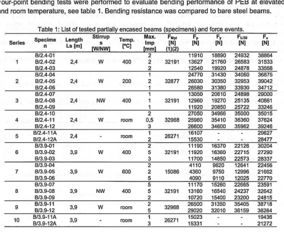
Four-point bending tests were performed to evaluale bending performance of PEB aI elevaled and roam lemperalure, see lable 1. Bending resislance was compared lo bare sleel beams.
Table 1: List cf tested partially encased beams (specimens) and force events.
Specime Length Stlrrup Temp. Max. F •• F, F, F"" F.
Serles n s Imp [N] [N] [N] [N] [N]
Ls [ml
~/N~ rC] [mm] !1Il2!
B/2.4~01 2 11910 18890 24932 38864
8/2.4-02 2,4 w 400 2 32191 13627 21760 26583 31533
8/2.4-03 2 12540 19920 24878 3356B
8/2.4-04 1 24770 31430 34060 36875
2 8/2.4-05 2,4 W 200 2 32877 26030 30350 32953 39042
3 2,4 NW 400
4 8/2.4-11 2,4 W room 0,5 32968 25960 35410 36360 37624
8/2.4-12 3 26600 34600 35962 39246
5 B/2.4-11A B/2.4-12A 2,4 room 1 26271 16107 29627
2 15530 2B4n
8/3.9-01 2 11190 16370 22126 30204
6 8/3.9-02 3,9 W 400 5 32191 11920 16360 22715 27290
8/3.9-03 3 11700 14850 22573 28337
8/3.9-04 2 4110 9620 12641 22456
7 8/3.9-05 3,9 W 600 2 15086 4360 9750 12996 21662
22770
8 3,9 NW 400 32191
9 3,9 W room 32968
10
Paulo
A.
G. Piloto, Ana B. R. Gavilán, Luís M. R. Mesquita, Carlos Gonçalves, Luisa BarreiraTesls developed ai room lemperalure used quasi-slatic load incremenls. Slrain, displacemenl and cross section rolalion were delermined ai cenlral seclion (SM). Vertical and laleral displacemenls (ZG, YG) as well as cross seclion rolalion (8G) were delermined based on measuremenls of Ihree wire polenliomelric displacemenl Iransducers. Some importanl load evenls were recorded for each lest. The proportional limit force (F,), lhe force (Fy) using lhe inlersection melhod between two slraighl lines drawn from linear and non-linear inleraction of lhe vertical displacemenl; lhe load evenl for lhe displacemenl limil (FLJ30); and lhe maximum load levei for lhe asymplolic behaviour of laleral displacemenl (F,).
3.1 Bendlng of medium series at elevated temperature
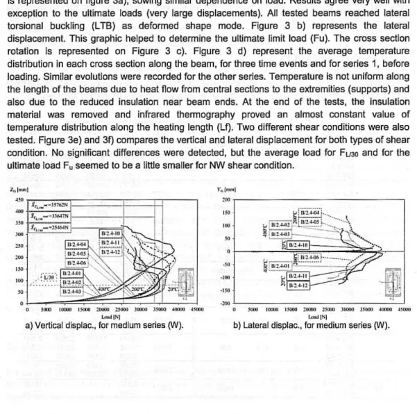
Figure 3 presents lhe resulls for lhe medi um lenglh series, showing lhe lemperalure effecl on bending using lhe same shear condition
0N).
The measured load versus vertical displacemenl is represenled on figure 3a), sowing similar dependence on load. Resulls agree very well wilh exceplion lo lhe ullimale loads (very large displacemenls). Ali lesled beams reached laleral lorsional buckling (LTB) as deformed shape mode. Figure 3 b) represents lhe laleral displacement. This graphic helped lo delermine lhe ullimale limil load (Fu). The cross section rolalion is represenled on Figure 3 c). Figure 3 d) represenl lhe average lemperalure dislribulion in each cross seclion along lhe beam, for Ihree lime evenls and for series 1, before loading. Similar evolutions were recorded for lhe olher series. Temperalure is nol uniform along lhe lenglh of lhe beams due lo heal fiow from central sections lo lhe extremilies (supports) and also due lo lhe reduced insulation near beam ends. AI lhe end of lhe lesls, lhe insulalion malerial was removed and infrared Ihermography proved an almosl conslanl value of lemperalure dislribulion along lhe healing lenglh (LI). Two differenl shear condilions were also lesled. Figure 3e) and 31) compares lhe vertical and laleral displacemenl for bolh types of shear condilion. No significanl differences were delecled, bul lhe average load for FUJO and for lhe ullimale load F, seemed lo be a little smaller for NW shear condilion.Za lmm]
"'~~n
i,,, ....
wJ576~N".
J',,, .... -,u6 .. rn'"
".
'"
""
""
: 1-
o 5l1OO~~~
10000 I ~ !OOOO :$00(1 JOOOO 15000:r.L:
.wooo:!j
4500IIl<-...J IN]
a) Vertical displac., for medi um serias 0N).
192
Y" lmm]
'00 ,---,
.~ ~----li 500J ---lOOlO 15000 10000 :$000 ]DOOO JSOOU .soooo C-J 45000
t.. .. d]N]
Experimental investigation on the perfonnance of partially encased beams at elevated and roam temperature
1I[r.ul )
o.' r - -- - - -- - - ,
u . ~
0,1
•. ' ".
--:-""' ~- ,-:-=~ -: ,-: ""' -:-:-:- ,= =--:c,""'
=~
'"""' ':::--,,:::
''' -:--:, -:' ="",'::- -='~ l (l OO
I.n>dIN]
c) CroS5 secUon rot., for medium series 0fV).
1.,,1"""1
150
""
""
""
lO . .... ... ."'
. o SOOO 10100 l !OOO 1DOOO !5000 JOOOO J!1XlO 40m0 _uoooI.n>d [N]
e) Vertical displac., for medium series 0NINW).
T("t']
""
lP ,~""~ ,,, ~ , :r--:
~ 1!:!.:. ~ 411~ -~ -~ - ~- ,~-- -~,~~ - .~- -~-~-;:---
--
I
1 ~'1A-Ol
""
'00
d) Temperature dist. and evol. for series 1.
YCo lmm1
lOOO 10000 l lOOO 10010 251100 JOI'( lIl )Suou 4o.nl 41000
Fu<= IN[
f) Lateral displac., for medium series rN/NW). Figure 3: Bending behaviour at elevated temperature for medium series.
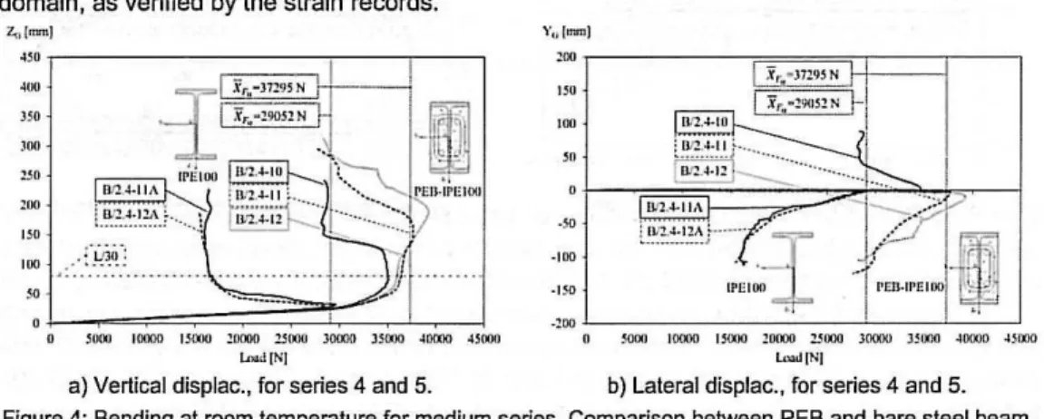
3.2 Bending of medium series at room temperature, using PEB and bare steel beam
lhe bending performance of PES was also compared with lhe performance of bare sleel beam ai room lemperalure, using lhe same sleel profile. lhe defleclion behaviour if differenl, besides bolh atlained lhe lateral lorsional buckling as deformed shape mode, see figure 4. lhe bending stiffness is also higher for lhe case of PESo Sare sleel beams behaved on lhe elaslic and plaslic domain, as verified by lhe slrain records.
no.' '' "
1---- >
l'''':':'!A;
-,;" oo ::r
- I{ ,~ -,: ,J - m
_'00
L.--, =-::=-::~'
+=-'--:=-:,:::--:~I=-·~
,
--::'
~l 10000 151)10 1010J 2!lOOO Joooo J ~ lIOO ~1lOOO ~jOOfl
·' 00
., ~
l=I [N[ l<\o1Il [N[
Paulo A. G. Piloto, Ana B. R. Gavilán, Luís M . R. Mesquita, Carlos Gonçalves, Luisa Barreira
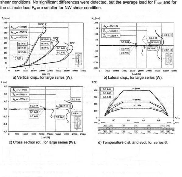
3.3 Bending of large series at elevated temperature
Figure 5 represenls lhe resulls for lhe large beam lenglh series, camparing lhe eflecl of lemperalure levei on bending performance uslng lhe same shear condilian f'IV). The graphics for vertical displacemenl are plolled againslload, as represenled in Figure 5 a), sowing similar
dependence on load. Results agree very weU wilh exceplian lo lhe behaviour ai higher and ullimale loads (very large displacemenls). AUlesled beams reached lalerallorsianal buckling as defarmed shape made wilh exceplion for lhose lesled aI 600 ' C. Plaslic hinge formalion was
lhe dominanl deformed shape mode verified for series 7. Figure 5 b) represenls lhe typical laleral displacemenl for lhe deformed shape mode. The cross seclian rolalion is represenled on Figure 5 c). Figure 5 d) represenl lhe average lemperalure dislribulion along lhe beams af series 5, for lhree time evenls, before loading. Twa diflerenl shear condilions were alsa tested for large beam series. Figure 5 e) and f) compares the vertical and lateral displacement for both
shear conditions. No significant diflerences were detecled, but the average load for FulO and for the ultimate load F, are smaUer for NW shear condition.
l,,[mm l
'"
""'"
"'"
,
"
.
..
!.lill
""
"0
,.,
'"
~ 10000 uono :!OOOO !!lOOO JOOOO lSOOO ~OO)O ~ j!XXI ~ llllllO I SllII1 :00111 !.liOOO }OIlIII lSOOO 41l1ffl 451100
lnaa!IN] t...J[N]
a) Vertical disp., for large series (W). b) Lateral disp., for large series (W).
Trel
, J-"---:-:-_----:----:_----:_---: __ ~ ""
o ~ U M ~ I
'-., '- "-
.,'-_ J'ê ""
o
je
'iI'1L'ªª
~ 10000 UOOO ~oooo 13000 lOOOO l~ ~oooo ~ sooo
LmallN1
c) Cross section rot. , for large series fY'J). d) Temperature dist. and evol. for series 6.
Experimental investigation 00 the performance of partially encased beams at elevated and roam temperature
'"
'00""
".
"0 '00'"
!OOO 1!lOOO I !OOO ~ OOll) ~ 5000 JIXIOO lSOOII ~uoo o 4~IXM )
t..wl]N]
e) Vertical displac., for large series CN/NW).
NW ' • I
I ·
· [OU
.,'"
v-?
J .:;;;;.,:.;,;
~
~ \ r l
....
·IJ"
.,
., .. L-_ __ __ _ _ _ l...L _ _ _ _ '--...J
sooo l OOCXI [5000 ~oooo ~)() ]0(01) )3I)Wl JOO)O ~ llllll [ ~1>Ii [Nl
f) Lateral displac., for large series (W/NW).
Figure 5: Bending behaviour at elevated temperature for large series.
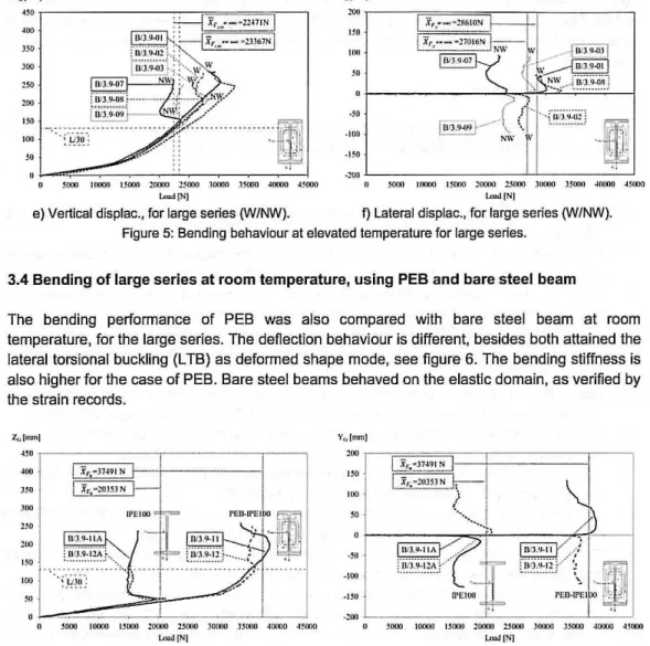
3.4 Bending of large series aI roam lemperalure, using PEB and bare sleel beam
The bending performance 01 PEB was also compared wilh bare sleel beam ai roam lemperalure, for lhe large series. The deflection behaviour is dilferenl, besides bolh atlained lhe laleral lorsional buckling (L TB) as deformed shape mode, see figure 6. The bending stilfness is also higher for lhe case of PEB. Bare sleel beams behaved on lhe elastic domain, as verified by lhe slrain records.
Z,-;lrnm1
""
".
""
,.,
'00''''
''''
I
I
X,, -3149 1 N
I
:ir. - ~ OlSl N
I
11'1: 100'" L --=:~
lOOO IIlOO(I IlOOO ~ oooo~
HOOO 30000 HOOO~
~ !lOOO ~ lOOOl.o.+d (NJ
a) Vertical displac., for series 9 and 10.
Y,, (mm )
".
"O
,ro
'"
.'00
~ · / .~j r l§: :; r ;~ _~
[PEIOO
I:
PEIJ.!Pf: IOOW
-100 L-",:-:=:-:=-:-:.L-",=-=,,--=:-L,.,--·''-,-J(I ~ooo 1{O)(1 15000 l llOOll ~ 5000 JOOO(I 35000 JOOOO Jl OOO
· llO
LooJ IN]
b) Lateral displac., for series 9 and 10. Figure 6: Bending at roam temperature for large series. Comparison between PEB and bare steel beam.
4. CONCLUDlNG REMARKS
Twenty seven bending lesls were presenled lar medium and large series 01 PEB, using elevaled lemperalure leveis. The bending resislance of lhe PEB (roam) is almosl two limes lhe bending resislance of bare sleel beam. The reduclion an bending resislance 01 PEB is nol directly proportional lo lhe increase 01 lemperalure. An increase 01 lemperalure lrom 200'C lo
400 'C leads lo a reduclion of 24 % an FU30 for medium senes, while an increase lrom roam lo
Paulo A. G. Piloto, Ana B . R. Gavilãn, Luís M. R . Mesquita, Carlos Gonçalves, Luisa Barreira
600 ·C. lhe deformation af large bare steel beams is different from PEB. lhe bending stiffness of PEB (room) is 15% higher than the bending stiffness af bare steel beam. More experimental tests should be developed at higher temperature levei and with different cross section
dimensions.
5. AKNOWLEDGMENTS
Authors acknowledge material support to the following companies: Arcelor - Mittal (Spain), J. Soares Correia (Portugal), Fepronor (Portugal) and Hierros Furquet (Spain).
6. REFERENCES
{1] CEN - EN 1994-1-2; "Eurocode 4: Oesign af composite steel and concrete s(ruc(ures - Part 1-2:
General rules" -Slrue/ural rire design ; Brussels, August 2005, 109 p.
[2] R. Kindmann et ai; "Effect af reinforced concrete between lhe f1anges af the 5teel profile af parlially encased composite beam "; Joumal of Constructional Steel Research, 27, 1993 p. 107-122.
[3] Hosser D., Dom T., El-Nesr O., "Experimental and numerical studies af composite beams exposed to
fira", Joumal ofStructurat Engineering, VaI. 120, NO.10, 1994, p. 2871-2892.
[41 Lindner Joachim, Budassis Nikos; "Lateral tors. Buck. of parlially encased composite beams without concrete slab':· Comp. const. in steel and concrete IV. May 28th to June 2nd. Banft. Alberta. Canada.
2000. p.117-128.
[5} Maquoi R. et ai. (European commission), "Lateral torslonal buckling in steel and composite beams;
ISBN 92-894-6414-3: Technical Sleel Research Final Report EUR 20888 EN; Augusl 2002,301 p.
[6} Assi l.M., Abed S.M., Hunaiti Y.M., ~Flexural slrength of composite beams partially encased in lightweight concrete ", Pakistan Joumal of Applied $ciences 2(3), 2002. p. 320-323.
[7} Nakamura S., Narita N., QBending and shear strengths of partially encased composite I-girders",
Joumal of Constructional Steel Research, 59, 2003, p.1435-1453.
[8] Kodaira Akio el ai; 'Fire Resistance of Composite Beams Composed of Rolled Steel Prefile Concreted Belween Flanges"; Fire Science and TechnologyVol.23 Na.3, 2004. p. 192-208.
[9} Elghazauli A.Y., Treadway J. ulnelastic behaviour af camposite members under comblned bending
and axialloading", Joumal ofConstructional Sleel Research, 64, 2008, p. 1008-1019.
[10} Nardin S., EI Debs A.L.H.C .• ~Study of partially encased camposite beams with innovative pasitian af stud bolls", Joumal of Constructional Steel Research. Volume 65, Issue 2, February 2009, p. 342-350. [11} Correia A.J.P.M., Rodrigues J.P.C., "Fira resistance of partially encased sleel columns with restrained
thermal elongation ~, Joumal of Gonstr.Steel Research, Volume 67, Issua 4, April 2011. p. 593-601.
[12J Pilolo P.A.G., Gavilán A.B.R., Zipponi M. , Marini A .. Mesquila L.M.R., Plizzari G., "Experimenlal
investigation of lhe fire resistance of partially encased beams", Joumal of Constructianal Steel Research, Volume 80, January 2013, p 121-137.
[13J CEN - EN 1994-1-1; "Eurocade 4: Design of camposile sleel and concrete structures - Part 1-1: General rules and rules for buildings"; European Standard, Brussels, December 2004.118 p.
[14J ISO TC 164, ISO 6892-1; "Melallic malerials - lensile lesling - part 1: Melhod of lest at roam
temperature"; intemational standard, Switzerland, 2009. 65 p.
[15J IPQ (Inslilulo Português da Qualidade), NP EN 933-1 , "Tests for geomelrical properties 01 aggregales
- part 1; Determination of particle size dlstribution, sieving methad-, Portuguese standard, 2000, 16 p. [16} Keru Wu, Bing Chen, Wu Yaa, QStudy of the influence af aggregate size distribution an mechanical properties of concrete by acaustic emlssian technique", Gement and Concrete Research, Volume 31,
Issue 6, pp. 919-923, May 2001.
196