Joana Isabel Lázaro Almeida
Mestre em Engenharia Biomédica
Advances in solar-pumped laser
efficiency and brightness
Dissertação para obtenção do Grau de Doutoramento Engenharia Física
Orientador: Dawei Liang,
Professor auxiliar,
Universidade Nova de Lisboa
Júri:
Presidente: Prof. Doutora Maria Adelaide de Almeida Pedro de Jesus Arguente(s): Prof. Doutor Zhao Changming
Prof. Doutor Gonçalo Nuno Marmelo Foito Figueira Vogais: Prof. Doutor José Luís Campos de Oliveira Santos
Prof. Doutora Maria Adelaide de Almeida Pedro de Jesus Prof. Doutor Dawei Liang
Prof. Doutor Pedro Manuel Cardoso Vieira
Advances in solar-pumped laser efficiency and brightness
Copyright ©Joana Isabel Lázaro Almeida, Faculty of Sciences and Technology, NOVA University of Lisbon.
V
A
CKNOWLEDGEMENTS
This long journey would not have been possible without the help and support from many people. So, I would like to express my sincere gratitude to:
Firstly, my advisor Prof. Dawei Liang, who has been a tremendous mentor to me. I would like to thank for his constant support, dedication, and friendship demonstrated during all these years. This was a rewarding experience, not only at scientific level but also at personal level, that will influence me throughout my life, for which I thank you for this great opportunity.
My thesis committee members: Prof. Adelaide Jesus and Prof. Gonçalo Figueira, for their insightful comments and suggestions from various perspectives.
Dr. Emmanuel Guillot. As a SFERA and SFERA2 (FP7) European project PROMES-CNRS coordinator, he provided the opportunity to access the PROMES-CNRS solar facilities, which was crucial to conduct some of researches.
My colleagues in the Solar Laser Laboratory, in particular for Dário Garcia and Cláudia Vistas, for their valuable support and honest acquaintanceship.
Prof. Adelaide Jesus and Dr. Fernando Santana, Dean of the Faculty of Science and Technology of NOVA University of Lisbon, for their priceless help in choosing wisely the NOVA solar facility site within our University campus and support during its construction process. My sincere thanks also goes to Prof. José Paulo Santos and Prof. Paulo Limão for their valuable support in the post-construction of the NOVA facility.
Science and Technology Foundation of Portuguese Ministry of Science, Technology and Higher Education, for the attribution of the PhD fellowship.
Faculty of Science and Technology of NOVA University of Lisbon for the welcome as a PhD student. It was an honor to be able to grow up at this prestigious institution.
Prof. Luisa Carvalho for her optimism and encouragement, at both professional and personal level. I would like to thank for the precious support when times got tough.
My parents and brother for all the sacrifices that have made on my behalf. My deepest gratitude to my mother, for her shoulder and constant love, not only throughout this phase, but also throughout my life. I am also grateful to my family, with no blood ties, for all their unconditional support and friendship.
My beloved life partner, César, for his dedication, patience and love during all these years. You make my life complete.
VII
A
BSTRACT
Advances in both solar-pumped laser efficiency and brightness are herein presented. Several solar laser prototypes with both end-side-pumping and side-pumping configurations were studied and developed to efficiently pump small diameter Nd:YAG laser rods, leading to substantial increase in solar laser collection efficiency and brightness, which have gained international recognitions.
All the design parameters were optimized in ZEMAX© non-sequential ray-tracing software.
LASCAD© laser cavity analysis software was then used to optimize the laser resonator parameters.
Based on the numerically optimization of the solar laser system, the solar laser prototypes were designed and built in Lisbon. Solar energy collection and concentration were achieved through the PROMES-CNRS heliostat-parabolic system, NOVA Fresnel lens system, and the recently new NOVA heliostat-parabolic system. Measurements of the solar input / laser output performance, beam quality M2 factors, and laser beam profiles for both multimode and fundamental mode regime
were performed and compared with that of the numerical results.
13.9 W/m2 solar laser collection efficiency was achieved in 2013, through PROMES
heliostat-parabolic mirror system, by end-side-pumping a 5 mm diameter, 25 mm length Nd:YAG laser rod. This result was further increased to 21.1 W/m2, in 2015, within the same solar facility. In 2016, 25 W/m2 collection efficiency was reported, by end-side-pumping a thinner laser rod through
NOVA heliostat-parabolic mirror system. In addition to the enhancement of solar laser collection efficiency, the thermal performance of end-side-pumped solar laser was also substantially improved.In 2017, record solar laser collection efficiency of 31.5 W/m2 was reported by
end-side-pumping a 4 mm diameter, 35 mm length Nd:YAG laser rod in PROMES-CNRS heliostat-parabolic mirror system. Also, record slope efficiency of 8.9% was achieved.
A substantial progress in solar laser beam brightness with Fresnel lens was reported in 2013, through the first TEM00-mode solar laser. 1.9 W solar laser brightness was registered, being 6.6
times more than the previous record. The adoption of an asymmetric laser resonator, for maximum extraction of TEM00-mode solar laser, was also essential for improving significantly the solar laser
brightness. By side-pumping a 3 mm diameter, 30 mm length Nd:YAG rod with a double-stage rectangular light guide / 2D-CPC concentrator, 4.0 W solar laser brightness was reported in 2015, doubling the previous record with Fresnel lens. TEM00-mode solar laser collection efficiency of
4.0 W/m2 was obtained by side-pumping a Nd:YAG grooved rod in 2016. Most recently, by
end-side-pumping a 4 mm diameter, 35 mm length, Nd:YAG rod, the TEM00 mode solar laser collection
efficiency was almost doubled, reaching 7.9 W/m2. Record-high solar laser brightness of 6.5 W
was also achieved.
Advances in solar laser beam stability were also achieved by developing sculptured twisted light guides for efficient uniform redistribution of pump light into a thin and long laser rod. In addition to this, we were also able to demonstrate the first emission of doughnut shaped solar laser beam, which may widen the applications areas of solar-pumped lasers.
IX
RESUMO
Nesta dissertação são apresentados os avanços na eficiência e brilho de laser bombeado por luz solar. Vários protótipos de laser solar, com configurações de bombeamento longitudinal e lateral, foram estudados e desenvolvidos para bombear eficientemente cilindros de Nd:YAG de pequeno diâmetro, levando a um aumento substancial da eficiência de colecção e brilho de laser solar, tendo ganho reconhecimento internacional.
Os parâmetros do desenho dos protótipos foram optimizados no software de traçado de raios não-sequencial ZEMAX©. Por sua vez, os parâmetros da cavidade de ressonância foram
optimizados pelo software de análise de cavidade laser LASCAD©. Com base na optimização
numérica do sistema de laser solar, os protótipos foram então projectados e construidos. Para colectar e concentrar a energia solar para bombeamento foram utilizados os sistemas: heliostato - espelho parabólico de PROMES-CNRS, lente de Fresnel da NOVA, e heliostato - espelho parabólico da NOVA, recentemente construído. Em termos experimentais, foram efectuadas medições do desempenho da potência de laser em função da potência de bombeamento, factores M2
de qualidade do feixe laser, e perfil do feixe laser, em regime multimodo e de modo fundamental. As medições experimentais desenvolvidas foram também comparadas com os resultados numéricos.
Laser solar com eficiência de coleção de 13.9 W/m2 foi conseguido em 2013, utilizando uma
cavidade laser com configuração de bombeamento longitudinal - lateral para bombear um cilindro de Nd:YAG com 5 mm de diâmetro e 25 mm de comprimento, no sistema de heliostato - espelho parabólico de PROMES-CNRS. Este resultado foi posteriormente melhorado para 21.1 W/m2,em
2015, na mesma instalação de energia solar. Em 2016, 25 W/m2 de eficiência de coleção foi registado, utilizando uma cavidade laser com configuração de bombeamento longitudinal - lateral para bombear um cilindro fino, no sistema heliostato - espelho parabólico da NOVA. Além do aumento da eficiência de coleção, o desempenho térmico do laser solar com este tipo de configuração foi melhorado substancialmente. Em 2017, foi conseguida uma eficiência de coleção recorde de 31.5 W/m2, através do bombeamento longitudinal - lateral de um cilindro de Nd:YAG
de 4 mm de diâmetro e 35 mm de comprimento, no sistema de heliostato - espelho parabólico de PROMES-CNRS. Foi também registada uma eficiência de declive recorde de 8.9%.
Em 2013, foi conseguido um progresso substancial em brilho de laser solar com lente de Fresnel, através do primeiro laser solar de modo TEM00. 1.9 W de brilho de laser solar, 6.6 vezes
maior que o recorde anterior, foi registado. A utilização de cavidade de ressonância assimétrica para máxima extracção de laser de modo TEM00 foi também essencial para melhorar
significativamente o brilho de laser solar. Através do bombeamento lateral de um cilindro de Nd:YAG com 3 mm de diâmetro e 30 mm de comprimento, foi registado 4.0 W em brilho de laser, em 2015, duplicando o recorde anterior com lente de Fresnel. Em 2016, foi obtido um record de 4.0 W/m2 em eficiência de coleção de laser solar de modo TEM
00, através do bombeamento lateral
de um cilindro de Nd:YAG. Mais recentemente, ao bombear lateralmente um cilindro de Nd:YAG de 4 mm de diâmetro e 35 mm de comprimento, a eficiência de coleção de laser solar de modo TEM00 foi quase duplicada, atingindo 7.9 W/m2. Recorde em brilho de laser solar de 6.5 W foi
também obtido.
X
e longo. Foi também possível realizar a primeira emissão de laser solar em forma de donut, o que pode alargar as áreas de aplicação dos lasers bombeados por luz solar.
XI
CONTENTS
Acknowledgements ... V Abstract ... VII Resumo ... IX List of Figures ... XV List of Tables ... XXI List of Publications ... XXIII Publications included in the PhD thesis... XXIII Acronyms ... XXV
1 Introduction ... 1
1.1 Outline ... 3
2 Solid-state lasers ... 5
2.1 Light and matter interaction ... 5
2.1.1 Population Inversion ... 7
2.1.2 Metastable state ... 8
2.2 Laser Oscillator ... 9
2.2.1 Conversion of Pump Input to Laser Output Energy ... 10
2.3 Solar-Pumped Lasers ... 16
2.3.1 Laser Materials ... 16
2.3.2 State-of-the-Art ... 19
3 Solar energy collection and concentration systems for solar lasers ... 37
3.1 Parabolic mirrors ... 40
3.1.1 PROMES-CNRS Heliostat - Parabolic mirror system ... 41
3.1.2 NOVA Heliostat - Parabolic mirror system ... 42
3.2 Fresnel lenses ... 43
3.2.1 NOVA Fresnel lenses system ... 44
4 Modeling tools for solar lasers ... 47
4.1 ZEMAX© - Modeling of the Solar Laser System ... 47
4.1.1 Solar pumping source ... 48
4.1.2 Solar energy collection and concentration system and solar laser head ... 50
4.1.3 detectors - absorbed pump power analysis ... 52
4.2 Lascad© - Modeling of the solar laser resonant cavity ... 53
4.2.1 Finite Element Analysis (FEA) of thermal effects... 53
4.2.2 Gaussian ABCD Matrix Approach ... 56
XII
5 Advances in solar laser efficiency ... 59
5.1 13.9 W/m2 solar laser collection efficiency ... 61
5.1.1 End-side-pumping scheme with conical light-guide ... 61
5.1.2 Solar laser experimental results ... 63
5.2 21.1 W/m2 solar laser collection efficiency ... 64
5.2.1 End-side-pumping scheme with conical lens ... 64
5.2.2 Numerical optimization of the solar laser performance ... 65
5.2.3 Solar laser experimental results ... 66
5.2.4 Numerical analysis of the thermal performance ... 67
5.3 25 W/m2 solar laser collection efficiency ... 69
5.3.1 End-side-pumping scheme with large aspheric lens ... 69
5.3.2 Numerical optimization of the solar laser performance ... 70
5.3.3 Solar laser experimental results ... 72
5.4 31.5 W/m2 solar laser collection efficiency ... 72
5.4.1 End-side-pumping scheme with large aspheric lens ... 73
5.4.2 Solar laser experimental results ... 73
5.5 Summary of the advances in solar laser efficiency ... 75
6 Advances in solar laser brightness ... 77
6.1 1.9 W solar laser brightness / First TEM00 mode solar laser ... 77
6.1.1 Side-pumping scheme with large aspheric lens ... 77
6.1.1 Solar laser experimental results ... 79
6.2 4.0 W solar laser brightness ... 81
6.2.1 Side-pumping scheme with single light guide ... 81
6.2.2 Solar laser experimental results ... 82
6.3 5.5 W cw TEM00-mode solar laser power ... 83
6.3.1 Side-pumping scheme with large single light guide ... 83
6.3.2 Numerical optimization of the solar laser performance ... 86
6.3.3 Solar laser experimental results ... 87
6.4 4.0 W/m2 TEM00-mode solar laser collection efficiency ... 89
6.4.1 Side-pumping scheme with truncated ellipsoid-shaped concentrator ... 89
6.4.2 Numerical optimization of the solar laser performance ... 90
6.4.3 Solar laser experimental results ... 91
6.5 7.9 W/m2 TEM00-mode solar laser collection efficiency ... 92
6.5.1 Numerical optimization of the solar laser performance ... 92
6.5.2 Solar laser experimental results ... 93
6.6 Summary of the advances in solar laser brightness ... 95
XIII
7.1 Side-pumping scheme with twisted light-guide ... 98
7.2 Numerical optimization of the solar laser performance ... 100
7.3 Numerical analysis of input solar power dependent TEM00– mode solar laser performance 102 7.4 Solar laser experimental results ... 103
8 Doughnut-shape solar laser beam ... 107
8.1 Side-pumping scheme with large aspheric lens ... 107
8.2 Numerical optimization of the solar laser performance... 109
8.3 Solar laser experimental results ... 110
9 Conclusions and Future visions ... 113
Annexes ... 127
Highlights during the PhD project (2013-2017) ... 127
XV
L
IST OF
F
IGURES
FIG.2.1 - Intra-ionic radiative processes. ... 5
FIG. 2.2 - Relative populations in two energy levels (a) for thermal equilibrium, (b) for inversion threshold and (c) saturation in transition processes. ... 7
FIG.2.3 - Schematic energy level diagram of a three and four-level laser system. ... 8
FIG.2.4 - Schematic scheme of laser oscillation operation through a resonant cavity. ... 9
FIG.2.5 - Energy conversion process in a solid-state laser system. ... 10
FIG.2.6 - Standard solar emission spectrum in space (AM0) and on the Earth (AM1.5) (46), and Nd:YAG absorption bands (47). ... 11
FIG.2.7 - Schematic diagram of the TEM00-mode beam propagation along the asymmetric laser resonator with large RoC (radius of curvature) end mirrors. L1 and L2 represent the separation length of the high reflection (HR) mirror and partial reflection (PR) mirror, respectively, to the end face of the laser rod with length LR. ... 13
FIG. 2.8 - Solar-pumped TEM00 mode beam waist radius ω0 in the rod as function of solar power at the focus, for different L1/L2 resonators, numerically obtained by LASCAD© analysis (40). (a)–(d) output laser beam profiles at different pump powers for L1/L2 = 5.45 resonator. (e) Output laser beam profile for L1/L2 = 1 resonator. ... 14
FIG. 2.9 - Energy level diagram of Nd:YAG (48,49). ... 17
FIG. 2.10 - Absorption spectra of the 0.0%Cr3+/1.0% Nd3+:YAG, 0.1% Cr3+/1.0% Nd3+:YAG, and 3.0% Cr3+/1.0% Nd3+:YAG (47). ... 18
FIG. 2.11 - (a) Photograph and (b) Design ofthe Nd:YAG solar laserscheme(13). ... 20
FIG.2.12 - Solar-pumped Nd:YAG laser head (21) ... 21
FIG.2.13 - Blackbody-pumped solar laser concept (17). ... 21
FIG.2.14 - Schematic representation of the experimental setup (18). ... 22
FIG.2.15 -The laser head and resonator (22). ... 22
FIG.2.16 - Schematic illustration of the solar-pumped alexandrite laser (68). ... 23
FIG.2.17- (a) The primary concentrator mirror (b) The double-stage concentrator (25). ... 23
FIG.2.18 - Schematic of a resonator with a conical-toroidal reflector and a thin-disk (71). active medium (71). ... 24
FIG.2.19 - Test system for laser from natural sunlight (26). ... 24
FIG. 2.20 - The solar laser head positioned in the focal zone (29) ... 25
FIG.2.21 - (a) 2 m × 2 m Fresnel lens. (b) Liquid light-guide lens configuration (30). ... 25
FIG.2.22 - Photograph of the Nd:YAG laser head at the focus of the PROMES-CNRS MSSF (36). ... 26
FIG.2.23 - Multi plane mirror — Fresnel lens scheme for solar-pumped disk laser (73) ... 26
FIG.2.24 - Schematic set-up of the solar-pumped fiber laser experiment (77). ... 27
FIG. 2.25 - (a) The Cr:Nd:YAG laser resonator within the MSSF solar facility (b) Compound V-shaped pump cavity (56). ... 27
FIG.2.26 - The Nd:YAG laser head at the focus of the PROMES-CNRS MSSF (33). ... 28
FIG.2.27 - (a) The solar-pumped TEM00 mode Nd:YAG laser system (b) The laser head (42). ... 28
FIG.2.28 - Detailed view of the solar laser heads (53,54) ... 29
FIG.2.29- Schematic of the solar pumped laser (80). ... 29
FIG.2.30 - Photograph of the Nd:YAG laser head (34) ... 30
FIG.2.31 - Asymmetric resonator for TEM00 mode Nd:YAG laser (37) ... 30
FIG.2.32 - Solar-pumped TEM00-mode Nd:YAG laser system (38). ... 31
FIG.2.33 - Illustration of cascade energy transfer for solar pumped lasers (81). ... 31
FIG.2.34 - Example of a system where a two-stage solar concentrator is used to pump a VECSEL (82). ... 32
XVI
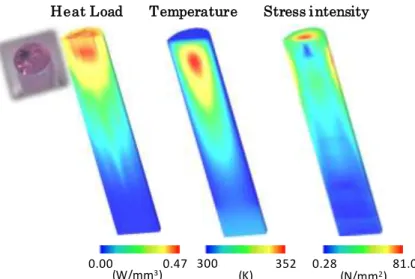
FIG.2.36 - Side-pumped laser design with a frequency converter (87). ... 33 FIG.2.37 - Design of novel Nd:YAG laser head (35). ... 33 FIG.2.38 - TEM00-mode laser power in PROMES-CNRS solar facility (31). ... 34 FIG.2.39 - Solar laser system with the twisted fused silica light-guide for the extraction of stable TEM00-mode laser power (91). ... 34 FIG.2.40 - Photo of the solar-pumped fiber laser (92). ... 35 FIG.2.41 - Experimental setup (a) Measurement system. (b) Structure of single active-mirror amplifier. (c) Two-stage active-mirror amplifier system. (d) Four-stage active-mirror amplifier system (93). ... 35 FIG. 3.1 - Concentration of sunlight by a parabolic mirror of focal length f and rim angle Фrim. ... 40 FIG.3.2 - (a) Scheme, (b) Flux distribution at the focus and (c) photograph of the PROMES - CNRS MSSF solar system. ... 41 FIG. 3.3 - (a) Scheme of the NOVA heliostat-parabolic mirror system. (b) Solar flux distribution of the heliostat-parabolic mirror, considering an irradiance of 900 W/m2 in ZEMAX analysis. ... 42 FIG.3.4 - The construction of the first automatic solar furnace in Portugal: (a) Preparation of the heliostat basement. (b) Installation of the heliostat pedestal. (c) Mounting of heliostat solar mirror. (d) Preparation of laboratory basement. (e) Installation of the mobile laboratory. (f) Finally built heliostat-parabolic mirror system. ... 43 FIG. 3.5 - Schematic design of a Fresnel lens from its corresponding aspheric lens. ... 43 FIG. 3.6 - (a) Schematic design of the chromatic aberration of a Fresnel lens. (b) Wavelength dependency of both the focal length and the refractive index of the 1.1 m diameter NOVA Fresnel lens with 1.3 m principal focal length f. The inset photograph shows its chromatic aberration, slight below of the principal focal length. ... 44 FIG.4.1 - Non-sequential objects of ZEMAX© software to model a Fresnel lens solar system. ... 47 FIG.4.2 - Source objects in ZEMAX©. ... 48 FIG. 4.3 - List of some the parameters of the source ellipse for the solar pumping source in the Non-Sequential Component Editor. ... 48 FIG.4.4 - Solar source wavelength data, for solar-pumping of a Nd:YAG laser. ... 50 FIG.4.5 - Geometrical optical objects in ZEMAX©. Fresnel 1 and Aspheric Surface represent the objects selected to model the Fresnel lens and Parabolic mirror systems, respectively. ... 51 FIG.4.6 - Selection of the Material parameters in the Non-Sequential Component Editor. ... 51 FIG.4.7 - Transmission data of the Nd:YAG laser material. ... 52 FIG.4.8 - (a) Design of the active medium and detector volume in ZEMAX© software. (b) Absorbed pump flux distributions along five transversal cross sections and one central longitudinal cross section of an end-side-pumped Nd:YAG rod (34), obtained by ZEMAX© numerical simulation through the detector volume. 53 FIG. 4.9 - (a) Crystal and pumping configuration models of LASCAD© software. (b) Laser pumping parameters, obtained through ZEMAX© data file. ... 54 FIG. 4.10 - (a) Cooling parameters of an end-pumped laser system in reference (34) (b) Nd:YAG laser material parameters. ... 54 FIG.4.11 - Semi-unstructured grid in case of a laser rod. ... 55 FIG.4.12 - Heat load, temperature and stress intensity distributions, numerically simulated in LASCAD© for a 5 mm diameter, 25 mm length Nd:YAG rod (34)... 56 FIG.4.13 - Parabolic approach for determination of the representative element of the active medium inside the resonant cavity. ... 56 FIG.4.14 - Representation of the resonant cavity and laser beam in the propagation planes X-Z and Y-Z for the efficient production of fundamental mode solar laser power (38). ... 57 FIG. 4.15 - Numerically calculated laser output power as function of (a) the absorbed pump power and (b)the reflectivity of the output coupler, for Ref. (38). ... 57 FIG.4.16 - (a) BPM Laser Beam Radius over cavity iteration and (b) output mirror beam profile, for ref.
XVII
FIG. 5.1 - (a) The Nd:YAG laser head positioned at the focus of the PROMES-CNRS 2 m diameter parabolic mirror. (b) The mechanical structure of the Nd:YAG laser head. Both the 1064 nm HR coating and the output coupler form the laser resonant cavity . ... 61 FIG.5.2 - The conical-shaped fused silica light guide with 3D-CPC output end coupled to the conical pump cavity where the 5 mm diameter Nd:YAG laser rod is efficiently pumped... 62 FIG.5.3 - Solar input / Nd:YAG laser output performance for different output coupler reflectivity from (a) the previous side-pumping configuration (36) and (b) the present end-pumping configuration (33). ... 63 FIG.5.4 - (a) Nd:YAG laser head positioned at the focus of the PROMES-CNRS 2 m diameter parabolic mirror. (b) Photograph and (c) mechanical design of the Nd:YAG laser head, composed of the fused silica conical lens, conical pump cavity, and Nd:YAG rod, which was actively cooled by water... 64 FIG.5.5 - Absorbed pump flux distribution along the 5 mm diameter, 25 mm length Nd:YAG rod pumped through (a) the present double stage conical lens / conical pump cavity and (b) the previous double stage conical light guide with 3D-CPC output profile / conical pump cavity (33). ... 65 FIG.5.6 - Numerically calculated laser output power as function of solar power at the focus, for the RoC =
−1 m output mirror with three different reflectivities. ... 66 FIG.5.7 - Solar input power versus Nd:YAG laser output power achieved by the present (34) and previous (33) end-side-pumping configurations, for R = 94%, RoC = -1 m output mirror... 66 FIG. 5.8 - Heat load, temperature and stress intensity distributions, numerically simulated in LASCAD© analysis, for the 5 mm diameter, 25 mm length Nd:YAG rod. The inset photograph shows the damaged Nd:YAG laser rod input end. ... 67 FIG. 5.9 - Heat load, temperature and stress distributions, numerically simulated for the 5 mm diameter composite YAG / Nd:YAG rod. ... 68 FIG.5.10 - (a) Design of novel Nd:YAG laser head, composed of the a large fused silica aspheric lens, the conical pump cavity and the Nd:YAG rod, which were all actively cooled by water. (b) Stationary Nd:YAG solar laser emitting at the focus of NOVA primary parabolic mirror concentration system. ... 70 FIG. 5.11 - Absorbed pump-flux distribution along both one longitudinal central cross-section and five transversal cross-sections of the 4 mm diameter, 35 mm length Nd:YAG rod. ... 71 FIG. 5.12 - Numerically calculated laser output power as function of solar power at the focus, for three different reflectivity (R = 90%, 94% and 98%) output mirrors. Laser slope efficiencies are also indicated. .. 71 FIG.5.13 - Solar laser output power versus solar input power at the focus, achieved by the R = 94%, RoC = -5 m output mirror positioned at different cavity length, L1 = 10 mm and L2 = 60 mm respectively. ... 72 FIG. 5.14 - (a) Laser head and output coupler were separated by 11 mm for producing the maximum multimode laser power . (b) Design of Nd:YAG laser head. ... 73 FIG.5.15 - Solar laser output power versus solar input power at the focus of the parabolic mirror, for R = 95%, RoC = -10 m and R = 94%, RoC = -5 m output couplers. ... 74 FIG.5.16 - Summary of the solar laser collection efficiency and slope efficiency advances during the PhD project and comparison with the previous record. ... 75 FIG.6.1 - (a) The solar-pumped TEM00 mode Nd:YAG laser system (b) The laser head. L1 and L2 represent
the separation length of the high reflection (HR) and partial reflection (PR) ... 78 FIG.6.2 - Detailed 3D view of the solar laser head. ... 78 FIG. 6.3 - Schematic diagram of theTEM00-mode beam propagation along the asymmetric laser resonator with large RoC end mirrors, obtained through LASCAD© analysis... 79 FIG. 6.4 - Dependence of laser power, M2 factor and brightness figure of merit on resonator length L1 is measured. ... 80 FIG.6.5 - Measured output laser beam profile 40 mm away from the output coupler. ... 80 FIG. 6.6 - Solar-pumped TEM00 mode Nd:YAG laser by the PROMES-CNRS heliostat-parabolic mirror
XVIII
FIG.6.9 - Front-view of the asymmetric laser resonant cavity for extraction of TEM00-mode laser. L1 and L2 represent the separation length of the high reflection (HR) and partial reflection (PR) mirrors to their nearest end face of the laser rod... 83 FIG.6.10 - (a) 3D design of the solar laser head, composed of the rectangular light guide, the 2V-shaped pump cavity and the 4 mm diameter, 30 mm length 1.1 at.% Nd:YAG rod. (b) Pump light distribution at different sections along the light guide. Uniform pump light distribution is achieved at L = 70 mm. ... 84 FIG.6.11 - Numerical absorbed pump flux distributions along the central and longitudinal cross-sections of the 4 mm diameter, 30 mm length, 1.1 at.% Nd:YAG rod pumped through the present scheme (a) with no tracking error and (b) considering 0.1º combined tracking error in X,Y axes. ... 85 FIG.6.12 - Numerical absorbed pump flux distributions along the central and longitudinal cross-sections of the 3 mm diameter, 30 mm length, 1.1 at.% Nd:YAG rod pumped through the previous scheme (37) (a) with no tracking error and (b) considering 0.1º combined tracking error in X,Y axes. ... 85 FIG.6.13 - (a) The 2V-shaped pump cavity, within which the 4 mm diameter Nd:YAG rod is efficiently pumped due to multi-pass absorption of pump radiation. (b) Examples of the passage of the pump rays with different incidence angles within the 2V-cavity. ... 86 FIG.6.14 - Numerically obtained absorbed pump power as function of the light-guide width DX. ... 86 FIG. 6.15 - Numerically calculated (a) rod focal length, (b) temperature and (c) heat load in the rod, for different input solar powers, assuming T = 300 K water cooling. ... 87 FIG.6.16 - Laser output power (at L1 = 580 mm) as function of the solar input power at the focus. ... 88 FIG.6.17 - (a)-(d) Evolution of output laser beam profile (taken 1.7 m away from the output coupler) with pump power as it approaches the resonator stability limit. (e) 2D analysis of the measured TEM00-mode profile. ... 88 FIG.6.18 - The solar laser head, composed of the truncated ellipsoid-shaped fused silica concentrator and a 2V-shaped pumping cavity within which the grooved Nd:YAG rod is efficiently pumped. ... 89 FIG.6.19 - (a) Front-view and (b) side-view of the simple solar laser pumping approach are illustrated by ZEMAX© shaded models. ... 90 FIG.6.20 - (a) A circularly symmetric uniform absorbed pump flux distribution of the 4.0 mm diameter grooved rod by ZEMAX© numerical simulation.
(b) Numerically simulated TEM00-mode laser beam pattern on the output mirror of the asymmetric laser resonator with RoC = –5 m for the 3.5 mm diameter grooved rod in LASCAD© BPM propagation.... 90 FIG. 6.21 - TEM00 mode laser output power versus concentrated solar input power at the focus of the parabolic mirror. ... 91 FIG. 6.22 - Measured TEM00 mode output laser beam 2D and 3D profiles 2.5 m away from the output
coupler. ... 92 FIG. 6.23 - Absorbed pump-flux distributions along both one longitudinal central cross-section and five transversal cross-sections of the 4 mm diameter, 35 mm length Nd:YAG rod, obtained by ZEMAX© analysis. ... 93 FIG.6.24 - Laser resonator configuration for the efficient extraction of fundamental mode solar laser power. Numerically calculated TEM00-mode BPM beam profile at the PR1064 nm mirror is given in the inset image. ... 93 FIG.6.25 - Measured TEM00-mode output laser beam 2D and 3D profiles 284 mm away from the PR 1064
XIX
FIG.7.4 - Input solar power dependent TEMoo-mode solar laser powers and beam profiles from both (a) the conical-shaped end-side-pumped laser (31) and (b) the side-pumped laser by the symmetric twisted light guide (91). ... 102 FIG.7.5 - The solar laser head within the asymmetric resonator. ... 103 FIG.7.6 - 2D and 3DTEM00-mode output laser beam 2D and 3D profiles, measured 50 mm away from the
PR1064 nm mirror. ... 104 FIG.7.7 - Time dependent TEM00 mode solar laser power variations of both the end-side-pumped TEM00 mode laser (31) and the present side-pumped laser by the twisted light guide (91). ... 105 FIG.8.1 - (a) Photograph of the Nd:YAG solar laser head. (b) Front-view and (c) top-view of the laser head design. ... 108 FIG.8.2 - Photograph of the trapezoidal pumping cavity and examples of the passage of the pump rays with different incidence angles in ZEMAX© analysis. ... 108 FIG.8.3 - (a), (b) Numerical absorbed pump flux distributions along central and longitudinal cross-sections of the 4 mm diameter, 34 mm length, 1.0 at.% Nd:YAG rod pumped through the previous (39) and the present scheme, respectively, obtained through ZEMAX© analysis.
XXI
L
IST OF
T
ABLES
TABLE 2.1 - Important remarks for development of solar-pumped lasers ... 20
TABLE 3.1 - Solar collectors and concentrators for solid-state solar lasers. ... 37
TABLE 5.1 - Previous advances in solar laser efficiency and respective solar laser head configurations. ... 59
TABLE 5.2 - Thermal performance of the 5 mm diameter Nd:YAG rod as function of the Nd3+ concentration. ... 68
TABLE 5.3 - Thermal performances of the 1.0 at% Nd:YAG rod with different diameters. ... 69
TABLE 6.1 - Equations for laser beam quality measurements. ... 80
TABLE 7.1 - Proposed solar laser schemes with twisted guides. ... 98
TABLE 7.2 - Numerical orientation error dependent TEM00-mode laser performance of non-symmetric and symmetric twisted light guides. ... 101
XXIII
L
IST OF
P
UBLICATIONS
P
UBLICATIONS INCLUDED IN THEP
HD
THESISThis PhD thesis is based on the following publications in peer-reviewed journals:
I. Mehellou, S., Liang, D., Almeida, J., Bouadjemine, R., Vistas, C. R., Guillot, E. Rehouma, F. (2017) Stable solar-pumped TEM00-mode 1064 nm laser emission by a monolithic fused
silica twisted light guide. Sol. Energ.155, 1059-1071.doi: 10.1016/j.solener.2017.07.048
II. Bouadjemine, R., Liang, D., Almeida, J., Mehellou, S., Vistas, C. R., Kellou, A., Guillot, E.,(2017) Stable TEM00-mode Nd:YAG solar laser operation by a twisted fused silica
light-guide. Opt. Laser Tech. 97, 1-11. doi:10.1016/j.optlastec.2017.06.003
III. Liang, D., Almeida, J., Vistas, C. R., Guillot, E. (2017) Solar-pumped NdYAG laser with 31.5 W/m2 multimode and 7.9 W/m2 TEM
00-mode collection efficiencies. Sol. Energ. Mat.
Sol. Cells 159, 435-439. doi:10.1016/j.solmat.2016.09.048
IV. Liang, D., Almeida, J., Vistas, C. R. (2016) 25 W/m2 collection efficiency solar-pumped
Nd:YAG laser by a heliostat-parabolic mirror system. Appl. Opt. 55, 7712-7717.
doi:10.1364/AO.55.007712
V. Vistas, C. R., Liang, D., Almeida, J., Guillot, E. (2016) TEM00 mode Nd:YAG solar laser by
side-pumping a grooved rod. Opt. Commun. 366, 50-56. doi:10.1016/j.optcom.2015.12.038
VI. Liang, D., Almeida, J., Vistas, C. R., Oliveira, M., Gonçalves, F., Guillot, E. (2016) High-efficiency solar-pumped TEM00-mode Nd:YAG Laser. Sol. Energ Mat. Sol. Cells 145,
397-402. doi:10.1016/j.solmat.2015.11.001
VII. Almeida, J., Liang, D., Vistas, C. R., Bouadjemine, R., Guillot, E. (2015) 5.5 W continuous-wave TEM00-mode Nd:YAG solar laser by a light guide / 2V pump cavity. Appl. Phys. B -
Lasers and Optics 121, 473-482. doi:10.1007/s00340-015-6257-z
VIII. Almeida, J., Liang, D., Vistas, C. R., Guillot, E. (2015) Highly efficient end-side-pumped Nd:YAG solar laser by a heliostat-parabolic mirror system. Appl. Opt. 54, 1970-1977.
doi:10.1364/AO.54.001970
IX. Liang, D., Almeida, J., Vistas, C. R., Guillot, E. (2015) Solar-pumped TEM00 mode
Nd:YAG laser by a heliostat-parabolic mirror system. Sol. Energ. Mat. Sol. Cells 134,
305-308. doi:10.1016/j.solmat.2014.12.015
X. Almeida, J., Liang, D., Guillot, E., Hadi, Y. (2013) A 40W cw Nd:YAG solar laser pumped through a heliostat: a parabolic mirror system. Laser Phys. 23, 065801.
doi:10.1088/1054-660X/23/6/065801
XI. Liang, D., Almeida, J. (2013) Solar-pumped TEM00 mode Nd:YAG laser. Opt. Express 21,
XXIV
Other relevant publications in peer-reviewed journals during the PhD project:
XII. Oliveira, M., Liang, D., Almeida, J., Vistas, C. R., Gonçalves, F., Martins, R. (2016) A path to renewable Mg reduction from MgO by a continuous-wave Cr:Nd:YAG ceramic solar laser. Sol. Energ. Mat. Sol. Cells 155, 430-435 doi:10.1016/j.solmat.2016.06.046
XIII. Vistas, C. R., Liang, D., Almeida, J. (2015) Solar-pumped TEM00 mode laser simple design
with a grooved Nd:YAG rod. Sol. Energ. 122, 1325-1333. doi:10.1016/j.solener.2015.10.049
XIV. Liang, D., Almeida, J., Vistas, C. R., Guillot, E. (2015) Solar-pumped TEM00 mode
Nd:YAG laser by a heliostat-parabolic mirror system. Sol. Energ. Mat. Sol. Cells 134,
305-308. doi:10.1016/j.solmat.2014.12.015
XV. Almeida, J., Liang, D. (2014) Design of TEM00 mode side-pumped Nd:YAG solar laser. Opt.
Commun. 333, 219 225.doi:10.1016/j.optcom.2014.07.091
XVI. Liang, D., Almeida, J., Garcia, D.(2014) Design of high-power, high-brightness Nd:YAG solar laser. Appl. Opt.53,1856-1861. doi:10.1364/AO.53.001856
XVII. Liang, D., Almeida, J. (2013) Multi Fresnel lenses pumping approach for improving high-power Nd:YAG solar laser beam quality. Appl. Opt. 52, 5123-5132
doi:10.1364/AO.52.005123
XVIII. Liang, D., Almeida, J., Guillot, E.(2013) Side-pumped continuous-wave Cr:Nd:YAG ceramic solar laser. Appl. Phys. B - Lasers and Optics 111, 305-311.
XXV
A
CRONYMS
AM0 Air Mass Zero atmospheres
AM1.5 Air Mass 1.5 atmospheres
AR Anti Reflection
AUTOCAD AUTO Computer Aided Design
BPM Beam Propagation Method
CMOS Complementary Metal Oxide Semiconductor
CNRS Centre National de la Recherche Scientifique
CPC Compound Parabolic Concentrator
Cr Chromium
EU European Union
FEA Finite Element Analysis
FFT Fast Fourier Transform
GSGG Gadolinium Scandium Gallium Garnet
HR High reflection
LASCAD LASer Cavity Analysis and Design
LSC Luminescent Solar Concentrator
MSSF Medium Size Solar Furnace
Nd Neodymium
NIR Near Infra Red
PMMA PolyMethylMethAcrylate
PR Partial Reflection
PROMES PROcédés, Matériaux et Énergie Solaire
RoC Radius of Curvature
SFERA Solar Facilities for the European Research Area
TEM Transverse mode
XXVI
VECSEL Vertical External Cavity Surface Emitting Lasers
YAG Yttrium Aluminum Garnet
1
1
I
NTRODUCTION
The conversion of sunlight into laser light by direct solar pumping is of ever-increasing importance, since broad-band solar radiation, the most plentiful available form of energy, can be converted into coherent, collimated and narrow-band radiation. Compared to electrically powered lasers, solar laser is much simpler and reliable due to the complete elimination of the electrical power generation and conditioning equipments, offering the prospect of a drastic reduction in the cost of coherent optical radiation for high-average-power applications, leading to numerous environmental and economical benefits in the years to come.
Solar laser is a natural candidate for applications where sunlight is plentiful and there are few other energy sources available. Thus, it is a future emerging technology for space-based applications (1,2) where extended run times are required and where compactness, reliability, and efficiency are critical. As solar energy is the main continuous energy source in space, it can be used to pump solid-state lasers either directly or indirectly. In indirect solar pumping, the solar radiation illuminates solar cells to produce electricity, which powers diode lasers. However, direct solar pumping saves two energy conversion steps and thus is inherently more efficient, much simpler and more reliable. A significant shortcoming of semiconductor arrays is their limited life time and performance degradation over time, that seems to scale with the level of average output power. For high-power laser systems, the lifetime of these devices is one of the major factors limiting the lifetime of a laser system or even an entire system to the order of round about 3 years (3). Entirely avoiding semiconductor laser arrays by direct solar pumping of solid - state lasers exhibits potential to overcome the current limitations, enabling reliable space borne laser operation over a multitude of years. Since strength of sunlight in space is about twice that on the Earth, and there are four or five times the hours of sunlight due to the absence of clouds energy, space - based solar power generation would be a major step forward in terms of fulfilling energy needs. Among the potential space applications of solar lasers are remote sensing from space, deep space communications, wireless space power laser beaming (4), asteroid deflection, fuel-free photonic thrusters (5), orbital space debris removal (6,7). Solar laser has also large potentials for terrestrial applications such as material laser-based processing, micro/nano-material production and renewable energy cycles. Particular attention has been recently paid to the renewable magnesium (Mg) - hydrogen (H2) cycle that might lead us to future fossil-fuel-free Mg-based civilization (2,8).
Large amounts of heat and H2 are given off from the reaction of Mg with water. Mg has great
potential as an energy source because it has an energy storage density about ten times higher than that of H2. It can be easily stored and transported in the form of ‘pellets’ and when necessary reacts
with water to produce both H2 and thermal energy for fuel cell vehicle applications. However,
1.
I
NTRODUCTION2
The idea of solar-pumped lasers (solar lasers) appeared no long after the invention of laser (10). The first studies on solar lasers have been described in the literature since 1962 (11). The first solar-pumped laser was reported in 1963 by Kiss et al. using calcium fluoride (CaF2)
crystal doped with divalent dysprosium(Dy2+:CaF
2) at liquid neon (Ne) temperature (12). Shortly
thereafter, systems using the Sun to pump solid (13) liquid (14) and gaseous (15,16,17,18,19) active media were considered. However, research into solar pumped lasers has essentially converged in systems with solid-state materials operating in a continuous wave (cw) mode. Among various laser materials, solid lasers appear to be most attractive because of their inherent high energy density and compactness, their relatively low pumping threshold, and their potential for efficient solar-to-laser power conversion. Since the first Sun-pumped neodymium yttrium aluminum garnet (Nd:YAG) laser reported by Young in 1966 (13), optical and laser material advances have continued to improve the solid-state solar laser performance (20). Nevertheless, additional focusing systems are required to collect and concentrate solar radiation because natural sunlight does not provide power density sufficient enough to produce laser. Parabolic mirrors have long been explored to achieve tight focusing of incoming solar radiation (21,22,23,24,25). By mounting directly a 4 mm diameter, 75 mm length Nd:YAG single-crystal rod within a 50 mm diameter water-cooled flow tube at the focus of a 78.5 m2 area parabolic mirror, 18 W multimode
solar laser power was successfully produced in 1984 (21), leading to 0.23 W/m2 laser collection efficiency – defined as solar laser power achieved per unit area of a primary collector (W/m2). With
CPC (Compound Parabolic Concentrator) secondary and tertiary concentrators, solar laser collection efficiencies were gradually boosted to 6.7 W/m2 in 2003 (25). Previous limitations in the
size of Fresnel lenses made solar-pumped laser efforts relatively unsuccessful in their early stage. Nevertheless, most of the technologically significant effort has occurred during the past ten years, after the adoption of Fresnel lenses as primary solar concentrators (26), boosting significantly the solar laser efficiency. 18.7 W/m2 solar laser collection efficiency was firstly reported in 2007 by
pumping a 3–9 mm diameter and 100 mm length Chromium (Cr) co-doped Nd:YAG ceramic laser rod with a 1.4 m2 area Fresnel lens (26). The progress with Fresnel lens and Cr:Nd:YAG ceramic
laser medium has revitalized solar laser researches, revealing a promising future for renewable recovery of Mg from MgO (8,9,27,28). 19.3 W/m2 laser collection efficiency was later achieved in 2011 by exciting a 4 mm diameter, 25 mm length Nd:YAG single-crystal rod through a 0.64 m2
area Fresnel lens in direct solar tracking mode (29). This result triggered the discussions about which medium between Cr:Nd:YAG ceramics and Nd:YAG single-crystal was more suitable for solar lasers. Consequently, in 2012, record-high collection efficiency of 30.0 W/m2 was attained by
pumping a 6 mm diameter, 100 mm length Nd:YAG single-crystal rod through a 4 m2 area Fresnel
lens (30), while the laser output power was unexpectedly worse when pumping a Cr:Nd:YAG ceramic rod. Most recently, both 31.5 W/m2 multimode and 7.9 W/m2 TEM
00 mode solar laser
1.
I
NTRODUCTION3
stress (25). Also, as the rod acts as an aperture, by pumping a small diameter laser rod, high-order resonator modes can be suppressed by large diffraction losses, and beam quality improves.
Despite the strong desire to achieve high solar laser efficiency (26,29,30,31,33,34,35), more attention should also be paid to the solar laser beam quality in order to attain tight focusing, which is very important for most laser applications. For these reasons, we have insisted on enhancing the solar laser efficiency and brightness by pumping small diameter Nd:YAG rods through heliostat–
parabolic mirror systems (31,36,37,38,39,40,41).
The brightness is one of the most important parameters of a laser beam. It is given by the laser power divided by the product of the beam spot area and its solid angle divergence. This product is proportional to the square of beam quality factor M2. Brightness figure of merit is thus defined as
the ratio between laser power and the product of Mx2 and My2 factors (25) – parameter that
quantifies the laser beam quality. The highest brightness figure of merit of an end-pumped solar laser is 0.086 W with Fresnel lens (29). Despite the successful production of 120 W cw end-pumped solar laser power in 2012, very large beam quality factors, Mx2= My2 = 137, have also been
measured (30), resulting in a dismal brightness figure of merit of only 0.0064 W. 0.29 W solar laser beam brightness figure of merit was achieved in 2011, by side-pumping a 4 mm diameter Nd:YAG rod through the heliostat – parabolic mirror system in PROMES-CNRS (36). This remained as a record-high value until 2013, through the first report of TEM00 mode solar laser (42) by our
research team. Gaussian TEM00 mode beams are by far the most common laser beam shape used in
materials processing (43), since it produces the smallest beam divergence, the highest power density, and thus highest brightness and ability to be focused to a diffraction-limited spot.
For these reasons, the main objective of this work was to enhance both the solar laser efficiency and solar laser brightness, which are essential for the above mentioned applications.Several solar pumping prototypes with end-side-pumping and side-pumping configurations have been proposed. All the design and solar laser parameters were firstly numerically optimized through ZEMAX© and
LASCAD© software, respectively. The final set-ups were designed and built in Lisbon, according
to the optimized parameters of the numerical analysis. The final tests of the solar laser performances were mainly carried out at PROMES-CNRS, through the participation in R&D projects supported by SFERA I and SFERA II projects(Solar Facilities for the European Research Area, 7th Framework Program of the EU), where the solar energy collection and concentration was achieved by the horizontal-axis Medium Size Solar Furnace (MSSF) solar facility (44). From 2015 to 2017, solar laser prototypes were also performed at theNOVA Solar Laser Laboratory, due to the recently new construction of NOVA heliostat-parabolic mirror system. Measurements of the solar laser output performance, including multimode and TEM00 mode laser powers, beam quality factors M2,
brightness figure of merit, were performed and compared with that of numerical analysis. The solar laser performance through Fresnel lenses system was also studied and tested. Significant progresses in both solar laser efficiency and brightness are herein reported, which are explained in detail in CHAPTER 5 and CHAPTER 6, respectively.
1.1
O
UTLINE1.
I
NTRODUCTION4
CHAPTER 2 covers the fundamental concepts of solid-state lasers. The solar-pumped lasers
concept is also described, including an overview of the suitable laser materials for solar-pumped lasers and a State-of- the Art.
CHAPTER 3 describes in more detail the solar energy collection and concentration systems
utilized for the solar laser prototypes.
CHAPTER 4 presents the modeling tools for the numerical optimization of the proposed solar
laser schemes.
CHAPTER 5 describes the efforts for enhancing the solar laser collection efficiency, reported in
the papers III, IV, VIII, X of the list of publications.
CHAPTER 6 describes the efforts for enhancing the solar laser brightness, reported in the
papers VI, VII, IX, XI of the list of publications.
CHAPTER 7 is dedicatedtothe presentation of two laser prototypes to increase the stability of
solar lasers, which is essential to obtain stable TEM00-mode solar laser, and thus, high brightness
solar laser beams. This was also reported in papers I and II in the list of publications.
CHAPTER 8 presentsthe report of doughnut-shape solar laser beam production, which is also a
very important class of beams for many applications, enabling novel fundamental insights in light-matter interactions.
CHAPTER 9 presents the conclusions of this work. Future perspectives on how to improve both
the solar laser efficiency and brightness are also discussed.
5
2
S
OLID
-
STATE LASERS
In this chapter, the basics of solid-state laser physics that are necessary in order to understand this work will be presented. It will start with the interaction of light and matter. The influence of the characteristics of the pumping source, pumping cavity, active medium and resonance cavity on the performance of the solid state lasers are described. It is also established the correspondence between these characteristics with the main parameters involved in the processes of energy conversion from pump input to laser radiation. This will be followed by an introduction of solar-pumped lasers, where it is described the solid state materials utilized for solar lasers, including their main advantages and disadvantages, ending with the state-of-the art of this technology, from the first solid-state solar-pumped laser to the most recent reports in 2017.
2.1
L
IGHT AND MATTER INTERACTION
The mechanism of a laser is based on the interaction of light and matter. If electromagnetic radiation interacts with matter, intra-ionic and inter-ionic processes occur. To understand the properties of laser, the focus here will be on the relevant intra-ionic processes. They can be either radiative, when photons are involved, or non-radiative, when phonons are involved. Atomic systems such as atoms, ions, and molecules can exist only in discrete energy states. A change from one energy state to another - called a transition - is associated with either the absorption or the emission of a photon, as represented in FIG. 2.1. An electromagnetic wave whose frequency, υ, corresponds to an energy gap of such an atomic system can interact with it. The wavelength of the absorbed or emitted radiation is given by Bohr’s frequency relation:
2 1 21
E E
E
h
(2.1)where E2 and E1 are two discrete energy levels, in which E2> E1, υ21 is the frequency, and h is
Planck’s constant (6.626×10⁻³⁴J.s).
FIG.2.1 - Intra-ionic radiative processes.
-- E1 E2 E3
Absorption
hυ= E2 - E1
-- -- -- - E1
E2 E3
Spontaneous emission photon
-- --
-E1 E2 E3
hυ= E2 - E1
Stimulated emission
hυ= E2 - E1
hυ= E2 - E1
2.
S
OLID-
STATE LASERS6
In this context, a laser medium can be considered an assemble of many identical atomic systems. When a large collection of similar atoms is in thermal equilibrium at temperature T, the relative populations of any two energy levels E1 and E2, such as the ones shown in Fig. 2.1, must be
related by the Boltzmann ratio:
2 1
2 2 2 2
1 1 1 1
'
exp
'
E
E
N
g N
g
N
g N
g
kT
(2.2)
where N1 e N2 are the number of atoms of the relative energy levels, E1 e E2; when two or more
states have the same energy, the respective level is called degenerate - represented by g; the states of the same energy level, for example E1, will be equally populated, therefore N1g N1 1´.
ABSORPTION
At thermal equilibrium, the lower energy states (E1) in the medium are more heavily populated
than the higher energy states (E2 or E3). An electromagnetic wave interacting with the laser system
will raise the atoms (ions, molecules) from lower to higher energy levels and thereby experience absorption. In this case, the population of the lower level, N1,will be depleted at a rate proportional
both to the radiation density ρ(υ) and to the population of that level:
112 1
t
N
B
N
(2.3)B12 is a constant of proportionality with dimensions cm3/s2.J, related to the probability per unit
frequency that transitions are induced by the effect of the field.
SPONTANEOUS EMISSION
After an atom has been raised to the upper level by absorption, the population of the upper level decays spontaneously to the lower level at a rate proportional to the upper level population:
2
21 2 t
N
A N
(2.4)where A21 is a constant of proportionality with dimension s− 1, related to the spontaneous transition probability to a lower level within a unit of time. Spontaneous emission is then characterized by the lifetime of the electron in the excited state, after which it will spontaneously return to the lower state and radiate away the energy. Contrary to the stimulated emission, spontaneous emission can occur without the presence of an electromagnetic field, where the emitted quanta is incoherent. Thus, the A21 Einstein coefficient represents a loss term and introduces into the system photons that
are not phase-related to the incident photon flux of the electric field, which means that the spontaneous process represents a noise source in a laser.
STIMULATED EMISSION
2.
S
OLID-
STATE LASERS7
a lower energy level to a higher one. In this case, an electromagnetic wave of appropriate frequency, incident on the “inverted” laser material, will be amplified. The stimulated emission is, in fact, completely indistinguishable from the stimulating radiation field, which has the same directional properties, same polarization, same phase, and same spectral characteristics. These facts are responsible for the extremely high degree of coherence which characterizes the emission from lasers.
Analogously to the absorption process, in the stimulated emission the population of the higher level, N2, will be depleted at a rate proportional both to the radiation density of the radiation field
ρ(υ) and to the population of that level, according to:
221 2
t
N
B
N
(2.5)where B21 is a constant of proportionality with same conditions as B12, from eq. (2.3). The Einstein coefficients for stimulated emission and absorption are equal (B21 = B12) when there is no degeneracy or if the levels have unequal degeneracy.
2.1.1
P
OPULATIONI
NVERSIONPopulation inversion is clearly an abnormal situation, since it is never observed at thermal equilibrium (FIG. 2.2(a)). Thus, to populate a higher energy level is required a source of energy –
pump energy to replenish the supply of upper-state atoms (FIG. 2.2(b)). The point at which the population of both states is equal is called the inversion threshold and the laser material is then transparent to the incident radiation. Nevertheless, spontaneous emission tends always to return the energy level populations to their thermal equilibrium values, which means that population inversion is not possible with materials of only two energy levels, even with higher pump energy density (FIG. 2.2(c)).
FIG. 2.2 - Relative populations in two energy levels (a) for thermal equilibrium, (b) for inversion threshold and (c) saturation in transition processes.
The pumping and laser processes in real laser systems typically involve a very large number of energy levels, with complex excitation processes and cascaded relaxation processes among all these levels. Operation of a laser material is properly described only by a many level energy diagram. E2 E1 Population, N E n e rg y le ve l , E N 2 N1
N2< N1
(a) (b) E2 E1 Population, N E n e rg y le ve l , E N 2 N1
N2= N1
Inversion Threshold Pump energy (c) E2 E1 Population, N E n e rg y le ve l , E N 2 N1 Pump energy
N2= N1
2.
S
OLID-
STATE LASERS8
2.1.2
M
ETASTABLE STATEThe existence of a metastable level is necessary for laser action. The relatively long lifetime of the metastable level provides a mechanism by which inverted population can occur, as demonstrated in FIG. 2.3. Most transitions of ions show rapid non-radiative decay, because the coupling of the internal atomic oscillations to the surrounding lattice is strong. Radiative decay processes occur, but most have short lifetimes and broad linewidths. Only a few transitions of selected ions in solids turn out to be decoupled from the lattice vibrations, which have a radiative decay that leads to relatively long lifetimes.
In three and four level laser systems, illustrated in FIG. 2.3, the 3 → 2 and 1 → 0 transition frequencies fall within the frequency range of the vibration spectrum of the host crystal lattice. For this reason, these transitions can relax extremely rapidly by direct non-radiative decay, emitting a phonon to the lattice vibrations with lifetimes
τ
32,τ
10≈ 10−8 to 10−11 s. Nevertheless, the transitions3 →0 , 3 → 1 , 2 → 0 ,and 2 → 1, with larger energy gaps, often correspond to transition frequencies that are higher than the highest possible vibration frequency of the crystal lattice. Since the lattice cannot accept phonons at those high frequencies, these transitions cannot relax via simple single-phonon spontaneous emission, but relax either by radiative photon emission or by multiple-phonon processes, which are relatively weak compared to direct single-phonon relaxation. Therefore, these transitions will have much slower relaxation rates (
τ
21≈ 10−5 to 10−3s). The energylevels from the pump band, E3, will then relax mostly into the metastable level, E2, which has a
long lifetime because there are no other levels located close below it, into which it can decay directly.
FIG.2.3 - Schematic energy level diagram of a three and four-level laser system.
In the absence of a metastable level, the ions which become excited by pump radiation and are transferred to a higher energy level will return either directly to the ground state by spontaneous radiation or by cascading down on intermediate levels, or they may release energy by phonon interaction with the lattice. Thus, population inversion cannot occur.
E
1E
3E
2 Abs or pt ionτ31 τ21 (slow)
τ32 (fast)
Population Inversion Pump band Short lifetime Long lifetime Metastable state LASER transition Three-level system
E
0E
2E
3 Abs or pt ion τ30τ10(fast)
τ32(fast)
Population Inversion Pump band Short lifetime Long lifetime Metastable state LASER transition Four-level system
E
1 τ31 Short lifetime τ202.
S
OLID-
STATE LASERS9
2.2
L
ASER
O
SCILLATOR
For a laser device, in addition to a laser material and pump energy to maintain a non-equilibrium state, it is also necessary to have a feedback mechanism for radiation to build up the amplified optical field. This requirement can be obtained by placing the laser medium into a laser resonator, as shown in FIG. 2.4.
The pump energy inverts the electron population in the laser material, leading to energy storage in the upper laser level (FIG. 2.4(b)-(f)). The role of the resonator, or resonant cavity, is to maintain an electromagnetic field configuration whose losses are replenished by the amplifying medium through stimulated emission. Thus, the resonator defines the spectral, directional, and spatial characteristics of the laser radiation, and the amplifying medium serves as the energy source. It is composed of two (or more) opposing mirrors (plane-parallel or curved) at right angles to the axis of the active material, enabling the laser beam to travel back and forth through the laser material, increasing the amplification of stimulated radiation (FIG. 2.4(c)-(f)). The amount of feedback is determined by the reflectivity of the mirrors. Lowering the reflectivity of the mirrors is equivalent to decreasing the feedback factor. One cavity mirror is high-reflection coated (about 100% reflectivity) for the laser emission wavelength, while the mirror (output coupler) must be only partial reflection coated for the same wavelength, for a fraction of the radiation to “leak out”
from the oscillator. Laser output emission occur (FIG. 2.4(f)) if the feedback and the gain are sufficiently large to compensate the internal losses of the system.
FIG.2.4 - Schematic scheme of laser oscillation operation through a resonant cavity.
High reflection
mirror (100%) Partial reflection mirror (<100%)
(a)
Atom in thermal equilibrium
(b)
Pump energy
Excited atom
(c)
Spontaneous emission
(d)Stimulated emission
(e)
(f)