U
NIVERSIDADE DE
L
ISBOA
Faculdade de Ciˆencias
Departamento de Inform´atica
EMULATING NETWORK APPLICATIONS WITH A
SOFTWARE-DEFINED NETWORKING
ARCHITECTURE
Marcos Andr´e Alves Vasco
DISSERTAC
¸ ˜
AO
MESTRADO EM ENGENHARIA INFORM ´
ATICA
Especializac¸˜ao em Arquitectura, Sistemas e Redes de Computadores
Dissertac¸˜ao orientada pelo Prof. Doutor Fernando Manuel Valente Ramos e co-orientado pelo Prof. Doutor Alysson Neves Bessani
Acknowledgments
First and foremost, I want to thank my large family. Starting with my nuclear family, which is my biggest pride and inspiration. I am grateful to my parents for all the love and pride they have, not only in me, but in all their children. It is very gratifying to observe how our achievements are also their achievements. A thank you for all their effort in getting me this far, and for all the investment in my academic formation. To my sisters I give thanks, for all the love, companionship, comprehension, conversations, help, trouble and headaches they have given me over the years. I couldn’t have it any other way. Thank you to my brother-in-law, for all the advice he has given me. A special thanks to my grandmother, my dear aunts, my uncles, my grandfather and cousins. Thanks for making our family a Family, with all your love and smiles. Thanks to my godfather, for all the words of strength when I needed, and words of appreciation when I deserved. To my grandmother, aunts, uncles and cousins in Angola, thank you. I love you all, my family.
I wish to thank Cl´audia and Z´e. To Cl´audia, for accompanying me in this stage of my life, and for always being at my side, thank you. To Z´e for all his friendship, compani-onship, and lots of laughs over many years. I also thank him for deciding to enroll in this university, and making my college life even better. Thank you.
I want to thank all my friends from college, namely Tiago Antunes and Carlos ‘Guns’ Cˆandido. I have spent a lot of moments with them, working, partying, and chilling. Wha-tever the situation is, these people should be there, as well as Tiago Ficalho and Jo˜ao Ramos. To the ‘2a Fase’ class, thank you very much for all the moments we have been through, I loved sharing this college experience with you all. To the people from Lab25, thank you for all your companionship and help.
Last, but not least, I want to thank my advisors. To Professor Fernando Ramos, for accepting me as his student without knowing me, and for all his availability, patience and at ease demeanor in dealing with me, which allowed this year to be more relaxed than it should have been. To Professor Alysson Bessani, for giving me the opportunity to work on an interesting project. To him I owe a word of gratitude for my success in this stage of my life. To my two advisors, I give thanks for allowing me the opportunity to learn from them.
Resumo
A arquitetura das redes de hoje n˜ao ´e suficiente para responder `as necessidades empre-sariais e acad´emicas correntes. A raiz do problema est´a na complexidade dos planos de controlo e de gest˜ao (os protocolos e o software que coordenam os dispositivos de rede); em particular, devido ao forte acoplamento entre a l´ogica de decis˜ao e a l´ogica inerente a um sistema distribu´ıdo. Esta complexidade deriva do fato de as redes n˜ao possu´ırem um paradigma de controlo geral, pois n˜ao providenciam nenhuma abstrac¸˜ao para o seu controlo e gest˜ao.
Software-Defined Networking (SDN) ´e uma nova arquitetura de rede em que o con-trolo est´a desacoplado do reencaminhamento e ´e diretamente program´avel. S˜ao definidas trˆes abstrac¸˜oes: abstrac¸˜ao de encaminhamento, abstrac¸˜ao de distribuic¸˜ao de estado, e uma abstrac¸˜ao de gest˜ao global. A abstrac¸˜ao de encaminhamento permite que software de con-trolo (o controlador) possa comunicar com o plano de dados, atrav´es de uma Application Programming Interface(API) comum. A abstrac¸˜ao de distribuic¸˜ao permite que os pro-gramas de controlo de rede n˜ao tenham de tratar da disseminac¸˜ao e colec¸˜ao de estado; o controlador fornece uma framework que oferece `as aplicac¸˜oes total controlo sobre a rede sem que estas tenham de se preocupar com a forma como as suas decis˜oes se propagam na rede subjacente. Com a abstrac¸˜ao de gest˜ao global, as aplicac¸˜oes tˆem acesso a um modelo l´ogico da rede, podendo assim geri-la como um ´unico switch l´ogico.
O OpenFlow ´e uma das primeiras abstrac¸˜oes de encaminhamento em existˆencia, e tamb´em a mais comum. ´E um padr˜ao de comunicac¸˜ao entre o controlador e os dispositi-vos de rede que cria um ambiente geral de programac¸˜ao, generalizando o plano de dados. O OpenFlow opera nas tabelas de fluxos dos switches, de modo a providenciar um pro-tocolo aberto para programar a tabela de fluxos em diferentes dispositivos. Um switch OpenFlow comunica com um controlador remoto usando a API OpenFlow, atrav´es de uma ligac¸˜ao segura. A tabela de fluxos destes switches OpenFlow ´e povoada com en-tradas do tipo hcabec¸alho; ac¸˜oesi, de acordo com instruc¸˜oes fornecidas pelo controlador. O cabec¸alho de um pacote que chega ao switch ´e comparado com os cabec¸alhos das en-tradas na tabela de fluxos e, se houver uma correspondˆencia, as ac¸˜oes correspondentes a essa entrada ser˜ao aplicadas ao pacote. As ac¸˜oes suportadas s˜ao do g´enero: encaminhar os pacotes para uma certa porta, enviar para o controlador, ou descartar o pacote. Tipica-mente, quando um switch n˜ao consegue encontrar uma correspondˆencia entre um pacote
e as entradas na sua tabela de fluxos, envia o pacote para o controlador.
Os controladores providenciam uma abstrac¸˜ao da distribuic¸˜ao de estado. Tal como os sistemas operativos facilitam o desenvolvimento de programas fornecendo acesso con-trolado a uma abstrac¸˜ao de alto n´ıvel dos recursos de um computador (mem´oria, pro-cessamento, etc.), os controladores s˜ao sistemas operativos de rede, que providenciam uma interface de programac¸˜ao uniforme e centralizada para observar e controlar a rede. A interface tem de ser suficientemente generalizada para permitir um amplo espectro de aplicac¸˜oes de gest˜ao. O controlador n˜ao efetua a gest˜ao da rede, as aplicac¸˜oes implemen-tadas no controlador s˜ao respons´aveis por esta gest˜ao. O controlador apenas aplica as ac¸˜oes decididas pelas aplicac¸˜oes. Esta entidade diz-se ser logicamente centralizada pois para as camadas adjacentes esta ´e abstra´ıda como tal. O controlador n˜ao tem de ser centra-lizado – pode ser implementado, por exemplo, de uma maneira distribu´ıda. O importante aqui ´e que esta camada esconde a distribuic¸˜ao dos dispositivos de rede, e apresenta uma vista geral da rede para as aplicac¸˜oes.
Numa arquitetura SDN, o plano de gest˜ao ´e realizado pelas aplicac¸˜oes que correm no controlador, operando sobre uma abstrac¸˜ao da rede. Para qualquer requisito de controlo que possa existir, podemos escrever uma aplicac¸˜ao que o resolve. Para o nosso trabalho, iremos construir um load balancer, uma aplicac¸˜ao que particiona tr´afego por entre v´arios servidores replicados.
Uma soluc¸˜ao para aumentar a capacidade e disponibilidade de um servic¸o Web ´e ter m´ultiplos servidores trabalhando em conjunto como um ´unico recurso. Neste tipo de ar-quitetura, os pedidos s˜ao encaminhados para um dos v´arios servidores, numa maneira transparente ao utilizador. Num esquema de load balancing baseado em dispatcher, um dispositivo de rede ´e colocado no ponto de entrada da rede, que recebe os pedidos e os distribui pelos servidores. Este dispositivo, tipicamente chamado de load balancer, age como um front-end para o grupo de servidores, e corre um algoritmo de escalonamento para decidir como distribuir a carga por entre os servidores. Soluc¸˜oes correntes para este esquema de load balancing s˜ao conseguidas atrav´es de hardware de rede que pode custar alguns milhares de d´olares. Para al´em do mais, estas soluc¸˜oes implementam uma escolha de pol´ıticas de escalonamento r´ıgida, com personalizac¸˜ao limitada. Outra desvantagem das tecnologias correntes de load balancing ´e que estas permitem apenas particionar a carga por entre os servidores; n˜ao podendo portanto escolher o caminho que o tr´afego toma at´e ao servidor. Assim, uma grande vantagem da nossa soluc¸˜ao de load balan-cingusando SDN ´e que podemos escolher o caminho que o tr´afego toma para chegar ao servidor. Iremos verificar neste trabalho que a performance do sistema aumenta quando fazemos escalonamento n˜ao s´o de servidores mas tamb´em de caminhos.
Desenvolvemos uma aplicac¸˜ao que efetua load balancing em servidores conectados numa rede com a arquitetura SDN. A aplicac¸˜ao desenvolvida funciona como um m´odulo para o controlador POX. Este controlador funciona atrav´es de eventos: as aplicac¸˜oes
registam-se como listeners de eventos espec´ıficos; o controlador faz raise a estes eventos, normalmente despoletado por algum acontecimento do plano de dados. Tipicamente, um switchque recebe um pacote cujo cabec¸alho n˜ao corresponde a nenhuma entrada na sua tabela de fluxos, envia este pacote para o controlador. Esta ac¸˜ao despoleta o evento Pac-ket Inno controlador. A nossa aplicac¸˜ao de load balancing est´a `a escuta desses eventos, que normalmente ´e despoletado pelo primeiro pacote de uma nova conex˜ao. A aplicac¸˜ao escolhe o servidor que ir´a tratar deste pedido, escolhe o caminho por onde a comunicac¸˜ao se ir´a dar na rede, e instala regras nas tabelas de fluxos dos switches ao longo do caminho. Instala tamb´em regras nos mesmos switches para o caminho inverso que os pacotes de resposta ir˜ao tomar.
Este Load Balancer para SDN vem equipado com cinco algoritmos para escolher o servidor e trˆes algoritmos de escolha de caminho. Para escolha de servidor temos os algoritmos: Round Robin; Flow Connections e Server Connections – estes dois escolhem o servidor com menos conex˜oes, diferind no modo como esta informac¸˜ao ´e recolhida; Load– o servidor com menos carga no seu CPU ´e escolhido; e Response Time – o servidor que produz melhores tempos de resposta ´e selecionado. Os algoritmos de escolha de caminho s˜ao: Shortest Path – o caminho mais curto (com menor n´umero de hops) ´e escolhido e em caso de empate escolhe-se sempre o de menor identificador; Equal-Cost Multi-Path– tal como Shortest Path, escolhe-se o menor caminho, mas caso haja mais do que um caminho mais curto, efetua round robin entre estes; e Path Delay – escolhe-se o caminho que tem o menor atraso.
De modo a poder avaliar os v´arios algoritmos de balanceamento de carga, escolhemos o emulador Mininet Hi-Fi como ambiente de prototipagem. Este emulador, baseado nos containersdo Linux, permite a r´apida prototipagem de grandes redes usando apenas um computador. Cada n´o da rede (host ou switch) ´e colocado num container, que providencia um ambiente virtual com o seu pr´oprio namespace de rede. A rede virtual final obt´em-se conectando estes containers entre si atrav´es de links Ethernet virtuais. Os emuladores de redes conseguem correr c´odigo real com tr´afego interativo, e suportam topologias ar-bitr´arias com um baixo custo. Al´em disso, o Mininet consegue emular redes que suportem o paradigma SDN. O Mininet Hi-Fi distingue-se dos demais emuladores pois providencia recursos para se obter fidelidade de desempenho. Esta ´e conseguida usando mecanismos de isolamento e provis˜ao de recursos, e monitorizando a experiˆencia para verificar se esta corre de uma maneira realista.
Criou-se uma topologia baseada na topologia de rede fat-tree, com 4 servidores, 5 switchese 2 clientes. A experiˆencia consistiu em ter os clientes a efetuarem um elevado n´umero de pedidos aos servidores. Os servidores, ao receberem estes pedidos, efetuam processamento que imp˜oe carga variada no seu CPU, de modo a simular pedidos dife-rentes. Os clientes registam o tempo de resposta de cada pedido. Todos estes valores foram agregados e apresentados em diagramas de caixa (boxplots). Esta experiˆencia foi
repetida com diferentes distribuic¸˜oes para a variac¸˜ao da carga da CPU e para diferentes configurac¸˜oes dos algoritmos. Para todas as situac¸˜oes, ´e vis´ıvel uma melhoria signifi-cativa quando se efetua escalonamento de carga entre os v´arios caminhos dispon´ıveis. Isto verifica-se independemente do algoritmo de escolha de servidor. Conclu´ımos, ent˜ao, que uma soluc¸˜ao em SDN consegue n˜ao s´o ser melhor em termos de desempenho, mas tamb´em sair mais em conta em relac¸˜ao a custos de equipamento.
Palavras-chave: Software-Defined Networking, Mininet, Multi-path, OpenFlow, Load Balancer
Abstract
Current network architectures are ill-suited to meet today’s enterprise and academic requirements. The problem lies in the complexity needed to control and manage the network. This complexity stems from the strong coupling between the control and data planes. A novel network paradigm, Software-Defined Networking (SDN), was proposed to alleviate this problem. The main idea is to decouple the control and data planes, allow-ing the network to be programmatically controlled. A key entity in SDN architectures is the controller. This logically centralized entity acts as a network operating system, provid-ing applications with a uniform and centralized programmprovid-ing interface to the underlyprovid-ing network.
In this Thesis we will develop an application that performs server load balancing in a Software-Defined Network. Today’s load balancers are high-priced devices that have limited customizability. Furthermore, they can only balance load between the servers, and are forced to use the path the network provides. In an SDN architecture, performing server load balancing does not require these expensive and inflexible devices. A low-cost load balancing solution can be designed, further enhanced with the ability to schedule load not only between servers, but also between paths. In addition, the centralized network control permitted in SDN allows the collection of updated link information to be used by the same logically centralized entity that makes forwarding decisions, which permits dynamic scheduling algorithms to decide on a best path for network traffic. We will show that such a solution outperforms ones which are oblivious to the path the traffic takes.
Keywords: Software-Defined Networking, Mininet, Multi-path, OpenFlow, Load Balancer
Contents
List of Figures xv
List of Tables xvii
1 Introduction 1
1.1 Traditional Computer Networks . . . 1
1.1.1 Challenges . . . 1
1.2 SDN: A New Network Paradigm . . . 3
1.3 Motivation . . . 4 1.4 Contributions . . . 4 1.5 Work Plan . . . 5 1.6 Document Structure . . . 6 2 Related Work 7 2.1 Software-Defined Networking . . . 7 2.1.1 OpenFlow . . . 8 2.1.2 SDN Controllers . . . 10 2.1.3 Management Applications . . . 12 2.2 Load Balancing . . . 13
2.2.1 Current Load Balancing Solutions . . . 14
2.3 Emulating Software-Defined Networks . . . 14
2.3.1 Mininet . . . 15
2.3.2 Mininet Hi-Fi . . . 16
2.4 Final Remarks . . . 17
3 Load Balancing in SDN 19 3.1 The Load Balancer Application . . . 19
3.1.1 Flows . . . 21
3.1.2 Routing . . . 22
3.2 Load Balancing . . . 23
3.2.1 Handling Packet In Events . . . 23
3.3 Scheduling Algorithms . . . 24
3.3.1 Server Choice Algorithms . . . 25
3.3.2 Path Choice Algorithms . . . 27
3.4 Final Remarks . . . 28
4 Evaluation 29 4.1 Network Topology . . . 29
4.2 Mininet Hi-Fi Setup . . . 30
4.2.1 Virtual Links . . . 31 4.2.2 Virtual Hosts . . . 31 4.3 Experiment Setup . . . 31 4.3.1 Client . . . 31 4.3.2 Server . . . 32 4.3.3 Procedure . . . 32 4.3.4 Verifying Fidelity . . . 34 4.4 Results . . . 34
4.4.1 Changing Update Intervals . . . 36
4.4.2 Changing Service Time Distribution . . . 41
4.5 Discussion . . . 43 5 Conclusion 45 5.1 Future Work . . . 46 List of Acronyms 48 Bibliography 52 xiv
List of Figures
1.1 The 3 planes in current networks and SDN . . . 2
1.2 Current networks’ architecture and SDN architecture . . . 3
2.1 SDN Architecture and abstractions . . . 8
2.2 OpenFlow Switch . . . 9
2.3 View of a Dispatcher-based architecture . . . 13
3.1 Illustration of communication between the switches, the controller and the load balancer . . . 21
4.1 Network Topology used in the Experiments . . . 30
4.2 Cummulative Distribution Function for the base request service load dis-tribution function . . . 32
4.3 Pictoral explanation of boxplots . . . 34
4.4 Boxplot of the response times of all requests during the experiment . . . . 35
4.5 Comparison of Path Delay Algorithm Configurations . . . 37
4.6 Comparison of Server Choice Response Time Algorithm Configurations . 38 4.7 Comparison of Flow Connections, Server Connections and Load Config-urations . . . 39
4.8 Boxplot of the response times using optimal algorithm configurations . . 40
4.9 Cummulative Distribution Functions for the heavy-tailed and discrete uni-form distributions . . . 42
4.10 Boxplot of the response times with heavy tailed request service load dis-tribution function . . . 42
4.11 Boxplot of the response times with a continuous request service load dis-tribution function . . . 43
List of Tables
2.1 OpenFlow-Enabled Switch’s flow table . . . 10
3.1 OpenFlow Messages Used . . . 19
3.2 OpenFlow Events Handled . . . 20
4.1 Load Balancing Algorithms . . . 33
4.2 Server Choice and Path Choice Algorithm Pairs . . . 33
Chapter 1
Introduction
Computer networks are an integral part of modern society. They are the backbone of all web services used today, and have become crucial in the infrastructure of our businesses, homes and schools. An ever increasing number of devices are connected to the internet, and thus connected to a computer network. This work aims to reflect on a new network paradigm, called Software-Defined Networking (SDN), and its benefits in the control and management of a computer network.
1.1
Traditional Computer Networks
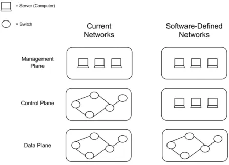
In current computer networks, functionality can be split into three main planes: data, control, and management. The data plane handles packet forwarding. Network devices route packets to their destination, sending them to the next-hop device along the path by forwarding the packets to one of its ports. Devices use information on their forwarding tables and on the packet’s headers to decide which port to send the packets to. The control plane consists of the distributed routing algorithms that fill the forwarding tables. Routers in interconnected networks exchange information about destination addresses using dy-namic distributed routing protocols. These devices must therefore understand and process a myriad of protocols. The management plane monitors the network and configures the data plane mechanisms and control plane protocols. A view of the three planes and how they are implemented in today’s networks can be seen in the left part of Figure 1.1. In it, we can see how the control and data planes are coupled in the switches. This means that all the functionality pertaining these two planes is achieved by all network devices working collectively.
1.1.1
Challenges
Computer networks have become part of the critical infrastructure of businesses, schools and homes, with an undeniable success. However, the original computer network archi-tecture is ill-suited to meet today’s requirements. When the mechanisms used in current
Chapter 1. Introduction 2
Figure 1.1: The management, control and data planes on current network architectures and SDN architectures.
networks were designed, they were simple. The original Internet Protocol (IP) control plane was designed to have a single distributed algorithm to maintain the forwarding ta-bles in the data plane [15]. Nowadays, however, things are more complex. Protocols have evolved to deliver higher performance, reliability, broader connectivity and rigor-ous security. These protocols tend to be defined in isolation, with each solving a specific problem without the benefit of any underlying abstractions. The result of this is the pri-mary limitation of today’s networks: complexity [30]. The TCP/IP and Open Systems Interconnection (OSI) layer models are good abstractions, but they only deal with the data plane. One of the main problems with current networks is a lack of powerful control plane abstractions [37].
In addition, the control requirements for today’s networks — Access Control Lists (ACLs), Virtual Local Area Networks (VLANs), middleboxes, etc. — add complexity to the operation and management of a network. These requirements lead to incremental changes in control plane protocols and complex management plane software, which re-sults in ever growing complexity [15]. State and parameters of network components are distributed across the network, making it difficult to guarantee state consistency among all network devices. This leads to management solutions that are both expensive and error-prone. For example, to implement a network-wide policy, possibly hundreds of de-vices and mechanisms must be configured. The complexity of today’s networks and the inherent difficulties in managing them makes it very difficult to apply a consistent set of access, security or Quality of Service (QoS) rules. This can result in network vulnerability to security breaches and enormous struggles for network managers [7, 30].
Chapter 1. Introduction 3
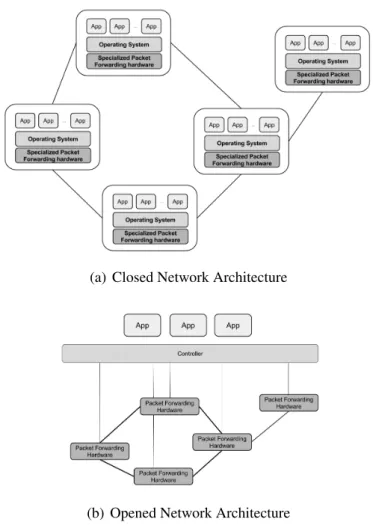
(a) Closed Network Architecture
(b) Opened Network Architecture
Figure 1.2: Logical view of the architecture of current networks and SDNs.
Current networks are relatively static as a result of their complexity, making it hard for them to innovate and to cope with several challenges. For example, due to this static nature, they cannot dynamically adapt to changing traffic, application and user de-mands [30]. Another consequence of the complex network architecture is the difficulty to scale. Every time a new network device is added to the network, it must be configured, and possibly several other devices must be reconfigured as well. To make matters worse, network devices from different vendors usually have different interfaces, which makes it more difficult to configure and manage all the devices in the network.
1.2
SDN: A New Network Paradigm
Due to the fundamental difficulties to operate and manage network control components using a distributed approach, in recent years some work has been done in refactoring the network control plane in a centralized approach [5, 7, 15]. A new networking paradigm, SDN, originated based on such ideas.
Chapter 1. Introduction 4
In Software-Defined Networks, the control plane is separated from the data plane. It is moved out of the individual network devices, to be implemented in software in separate servers. This allows the network to be programmatically controlled [30]. Network de-vices become simple, vendor-independent, packet forwarding dede-vices that no longer need to understand and process the wide range of protocol standards used in current networks. They simply receive packet forwarding and control instructions from a specialized en-tity (a network controller or network operating system). Network applications, such as routing, load balancing, etc., run on this logically centralized controller, as seen in Fig-ure 1.2(b). This is in clear contrast with current networks, where the control logic is embedded in all the network devices (Figure 1.2(a)). The controller maintains a global view of the network, supplying programmers with a simplified and programmatically con-figurable network abstraction. This makes it possible to easily implement and manage a wide range of network services, such as routing, access control, QoS, etc. [30]
We refer to the controller as a logically centralized entity because it is abstracted to both the applications and the switches as such. A physically centralized solution is likely to arise scalability concerns. However, the controller can be transparently implemented in a distributed fashion. As such, scalability issues can be reasoned about and tackled similar to any distributed system [40].
1.3
Motivation
In this work, we will develop and evaluate an SDN control application: a load balancer. Such a load balancer is accomplished using an inexpensive software application that runs on an SDN controller. Therefore, this low-cost solution is in stark contrast with cur-rent load balancing solutions, which are materialized by expensive network devices. We aim to show how simple it is to write a control application that performs load balancing custom-tailored to a specific scenario, as opposed to purchasing an expensive and rigid load balancing hardware. Furthermore, an SDN load balancing solution has the added benefit of considering network status when scheduling load. Different paths can be cho-sen to accommodate different network congestion scenarios, providing added flexibility and increased performance.
1.4
Contributions
Our work’s main contribution is the development and evaluation of a load balancing so-lution for a Software-Defined Network. We have:
Chapter 1. Introduction 5
• Evaluated and compared typical load balancing algorithms (round robin, number of connections, server load);
• Evaluated a novel algorithm that takes advantage of the ability to take network load into account when scheduling traffic. Current load balancing solutions can only choose the target server for a request, and are forced to use the path the network pro-vides. In our work, thanks to the network control permitted by an SDN architecture, our application can partition load between not only the servers, but also the paths traffic takes to get to the chosen server. This way we can effectively take network load into account when scheduling traffic, as opposed to taking only server load into account. This can be particularly beneficial in datacenter topologies, which are made to have multiple paths to a resource in the network;
• Tested and evaluated our load balancing control application using the Mininet Hi-Fi [18] network emulator. This emulator is used in virtually all SDN-related work. With Mininet Hi-Fi, we can emulate large networks in a single machine that sup-port the SDN paradigm. The virtual software switches connect to a remote SDN controller and can communicate using the OpenFlow [25] protocol. In addition to its support of Software-Defined Networks, Mininet Hi-Fi offers more realism and fidelity than simulators, and is cheaper, simpler and more flexible than a test bed.
1.5
Work Plan
Initially, our work plan consisted in:
• Task 1 (October – December 2012) — Literature survey and writing a preliminary report;
• Task 2 (December 2012) — Learning to use Mininet Hi-Fi;
• Task 3 (January 2013) — Emulate a load balancer using Mininet Hi-Fi on a Software-Defined Network
• Task 4 (February – April 2013) — Emulate JITeR [11] using Mininet Hi-Fi on a Software-Defined Network;
• Task 5 (April – June 2013) — Writing of the project’s report
The plan was slightly changed as we progressed in our work. We abandoned the idea of developing an application that mimics the behavior of JITeR due to three factors: 1) Mininet Hi-Fi was lauched in mid December, until then we worked with the previous version of Mininet that raised fidelity concerns. This caused a delay in the writing of a
Chapter 1. Introduction 6
preliminary report, and in all subsequent work; 2) we saw enough significance in extend-ing the study of the load balancer, in particular due to the possibility of partitionextend-ing traffic among multiple network paths, something we have not anticipated; 3) we saw the need to run a significant number of lengthy experiments of our load balancer application.
1.6
Document Structure
This document is organized as follows:
• Chapter 2 — Here we provide a discussion of the related work. We break down the structure of an SDN architecture and explain its inner workings. We describe the abstractions this novel network architecture provides and detail the implementations of the ones used in our work. Since we aim to create a load balancer, we give an explanation of what load balancing is, and how it is usually accomplished in today’s networks. We also provide a detailed description of the emulator we use in our work, Mininet Hi-Fi, and how it works.
• Chapter 3 — This chapter describes the design of the load balancer and the algo-rithms evaluated and proposed.
• Chapter 4 — Here we evaluate the different load balancing algorithms. We present the network topology used, and provide a detailed description of the experiments. We provide a discussion on how we set up Mininet Hi-Fi to accurately run our experiment, and show the results of several performance measures
• Chapter 5 — In the last chapter we present the conclusions we take from this work. We also present a discussion on things that can be improved as future work.
Chapter 2
Related Work
In this work we investigate how Software-Defined Networking (SDN) can improve net-work control and management. This chapter aims to detail the concepts and tools used in our work.
We will try to elucidate what SDN is, how it is accomplished, and how network man-agers may benefit from it.
To convey how relatively simple it is to solve network control problems in an SDN architecture, an application that performs load balancing was developed. We will de-scribe what load balancing is, how it can be useful, and how it is implemented in today’s networks.
As we wish to study how our load balancing solution performs, we deployed it in an emulated network environment provided by the Mininet Hi-Fi tool. We will unravel what this network emulator can do, how it works, and why it is useful in our work.
2.1
Software-Defined Networking
In this new network architecture, control is decoupled from the network devices, and is directly programmable. The network devices become simple packet forwarding devices, which receive control instructions from a logically centralized entity known as the con-troller. By logically centralized we mean that control logic is to be designed and operated as if it was a centralized application, rather than a distributed state [24]. However, the controller itself may be a distributed system, as is in fact the case with production SDNs, such as Google’s private Wide Area Network (WAN) [21].
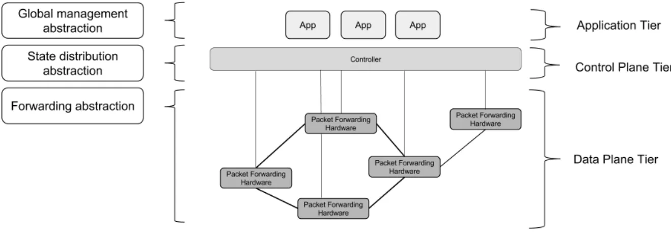
Current networks have no powerful control plane abstractions. SDN aims to solve this problem. The control plane is redefined as three abstractions: a forwarding abstraction, a state distribution abstraction and a global management abstraction. The forwarding ab-straction allows a software controller to communicate directly with the data plane, using a common Application Programming Interface (API) to program the network hardware. In SDNs, the materialization of this abstraction is most commonly done using
Chapter 2. Related Work 8
Figure 2.1: SDN abstractions and architecture.
Flow [25]. The state distribution abstraction shields control programs from the vagaries of distributed state. Thus, management applications no longer have to worry about dis-semination and collection of state. The logically centralized controller accomplishes the state distribution abstraction. With the global management abstraction the network has a logical appearance and can be managed as a single logical switch, rather than having to program each individual network device one at a time [37].
The network becomes divided in three tiers, as seen in Figure 2.1. The switches — now “dumb” packet forwarding devices — are located in the data plane tier; the controller and the network applications are in the control plane and application tiers, respectively.
2.1.1
OpenFlow
OpenFlow [25] is the most common forwarding abstraction in SDNs. It is the first stan-dard communications interface defined for the exchanging of information between the controller and the packet forwarding devices. While it is not mandatory to use OpenFlow, it is nowadays the most common standard used for the communication between SDN controllers and packet forwarding devices.
OpenFlow started out as a way for researchers to run experimental protocols in net-works used every day. As explained before, netnet-works today are static. A lot of the algo-rithms that are used, as well as functions, are fixed in hardware, in the network device’s chips. This results in a high barrier of entry for new ideas, due to the enormous installed base of equipment and protocols. Commercial solutions, meaning proprietary equipment, are closed and inflexible. Research solutions on the other hand, either have insufficient performance or are too expensive. OpenFlow, however, attempts to have switches support a broad range of applications, with high performance and low-cost implementations, all while being consistent with vendor’s need for closed platforms.
Chapter 2. Related Work 9
Figure 2.2: OpenFlow Switch’s Components. The flow table is managed by a remote controller using the OpenFlow protocol, via a Secure Channel [25].
be different, OpenFlow exploits a common set of functions that run in many network devices. The goal is to provide an open protocol to program the flow table in different network devices. This way, network traffic can be partitioned into production traffic and research traffic. Flows can be controlled, the paths that packets follow can be chosen, as well as the processing they receive. OpenFlow can be compared to the instruction set of a Central Processor Unit (CPU), since it specifies basic primitives that can be used by external software (in SDN, the controller) to program the forwarding plane of the network devices.
We present the three building blocks of an OpenFlow switch in Figure 2.2: a flow table, with an action associated with each flow entry; a secure channel connecting the switch to a remote controller; and the OpenFlow Protocol, which provides an API for the controller to communicate with the switch. The flow table is populated with flow entries of the form h header; action i, as decided by the remote controller. Packet headers are compared with the header field of flow entries on the switch. If there is a match, the action associated with the matched entry is performed on the packet. The switch does not have to know what it means in term of distributed state, it only knows what it is supposed to do.
There are three basic actions that all OpenFlow switches must support: forward the flow’s packets out to a certain port (or ports) so they can be routed through the network; encapsulate and forward a packet to the controller, typically used when there are no matches in the flow table (for the first packet of a flow), so the controller can decide on an action; and drop the flow’s packets. The OpenFlow protocol also allows for the modification of various packet header fields, such as source and destination addresses and ports. Counters are also maintained for each flow entry, recording the number of matching packets and bytes transferred.
Chapter 2. Related Work 10
MAC src MAC dst IP src IP dst TCP dport . . . Action Count
* * 10.1.1.2 192.168.* 35671 * port 1 1098 * 10:20:. * * * * port 2 250 * * * 5.6.7.8 * * port 3 300 * * * * 25 * drop 120 * * * 192.* * * local 120 * * * * * * controller 11
Table 2.1: An example illustration of an OpenFlow-Enabled Switch’s flow table [30].
A flow is a broad definition, limited only by the capabilities of the implementation of the flow table. This means that a flow can be a Transmission Control Protocol (TCP) connection, or packets from a particular Media Access Control (MAC) address, or packets with the same VLAN tag, and so forth. This can be observed in Table 2.1, which presents an illustration of a flow table with a subset of its various fields. Rules are ordered in priority. Wild carded fields (represented by *) enable a wide range of policies to be implemented in the network. As an example, the third rule in Table 2.1 will match on all packets with an IP destination address of 5.6.7.8, regardless of the remaining fields of the packet. The ability to allow a network to be programmed on a per-flow basis provides extremely granular control, which enables the network to respond to real-time changes at the application, user and session levels [30]. On OpenFlow-enabled switches there can be an additional action one can exert on a flow: to forward the flow’s packets through the switch’s normal processing pipeline. This allows isolation between experimental traffic and production traffic [25].
While the initial goal of OpenFlow was to foster innovation, allowing one to easily experiment a network protocol by dividing production and experimental traffic, the greater value of the OpenFlow API is that it creates a general programming environment for the data plane of a network. By generalizing the forwarding path it allows the decoupling of the distribution model from the control logic on the network elements.
2.1.2
SDN Controllers
Controllers offer a uniform and centralized programmatic interface to the entire network. Much like operating systems provide controlled access to high-level abstractions for the resources of a computer system, thus facilitating program development, the controller software is a “network operating system”, providing the ability to observe and control a network. The interface offered must be general enough to support a broad spectrum of network management applications [25].
Chapter 2. Related Work 11
of it perform the actual management [16]. The controllers form the control plane of the SDN network and the applications form the management plane. For example, the controller merely adds and removes flow-entries from the switches’ flow tables on behalf of the network management applications [25].
Some concerns about availability and scalability may arise when devising a network architecture based on a centralized controller. However, enough resilience can be achieved by applying standard replication techniques [16]. In fact, the term logically centralized is an oversimplification. What is important to note is that the distribution model is our choice to make, and not the network’s choice [37]. Thus, the controller can be a distributed system built and configured based on the specific requirements of scalability, resiliency, availability, etc. [22] All that is needed to maintain is a unified network view. As with any distributed system, the choice in consistency model offers a tradeoff between perfor-mance and overhead, which influences SDN scalability [40]. Furthermore, the OpenFlow protocol allows for a switch to be controlled by more than one controller, for increased performance and resilience [25].
Controllers present programs with a centralized programming model, allowing appli-cations to be written as if the entire network were present on a single machine. This is made possible by logically centralizing the network state. Controllers also allow programs to be written in terms of high-level abstractions, such as users and host names, instead of low-level configuration parameters, like IP and MAC addresses. Management rules can be enforced independent of the network topology; provided the controller maintains map-pings between these abstractions and the low-level configurations [7, 16].
There is already a significant number of controllers available to choose from: NOX [16], POX [32], Floodlight [12], Ryu [33], etc. We have decided to use POX, a Python version of the first SDN controller: NOX.
NOX
NOX was the first SDN controller made available. It tries to provide a modular and flex-ible framework for users to write control components that achieve control plane goals, using OpenFlow switches. A NOX-based network consists of a set of switches and one or more network-attached servers, running the NOX controller software and the man-agement applications over it. The NOX software consists of several different controller processes (one per server) and a single network view, kept in a database running on one of the servers. The network view contains the results of NOX’s network observations, and applications use this state to make management decisions [16].
NOX provides observation granularity at the switch-level topology, showing the loca-tions of users, hosts, middleboxes and other network elements [16]. As for control granu-larity, once control is enforced on some packet, subsequent packets with the same header can be treated the same way, meaning that control granularity is done at the flow level.
Chapter 2. Related Work 12
These granularity choices allow the system to scale to relatively large networks while still providing flexible control. The only component that is global (must be consistent across controller processes) is the network view.
When an incoming packet’s header does not match any flow entry at a switch, it is forwarded to the controller process. NOX uses these packets to construct the network view and applications running on NOX use them to determine the control actions to exert on the network. Typically a packet whose header does not match any flow entries is the first packet of a new flow. If the application decides to install an entry for this new flow, subsequent packets will match on the flow entry installed; the switch updates the appropriate flow counters and applies the corresponding actions.
Since NOX is responsible for establishing every flow in the network, it may become a bottleneck if it does not have enough capacity to handle all the requests. However, a single controller process can handle 100000 flow initiations per second [16], which is considered enough for a good range of networks [3].
NOX’s interface revolves around events, a namespace and the network view. Applica-tions use a set of handlers registered to execute when a particular event happens, typically triggered by the dataplane. Applications register for events, and NOX invokes a handler when an event occurs, processing each event individually. The application handler’s re-turn value indicates to NOX whether to stop the execution of an event, or to trigger the next registered handler. Events can be generated either in direct response to received OpenFlow messages, or by the applications as they process other events.
POX
POX [32] is the Python version of NOX. Its focus is on research and academia. NOX’s core infrastructure was implemented in C++; however, it allowed applications to be writ-ten in either Python or C++. As development of NOX progressed, developers saw the need to build separate Python and C++ versions. So POX was forked from NOX, but the basic idea and framework remains the same [26].
2.1.3
Management Applications
On top of the control plane resides the management plane. On an SDN architecture, the management plane is accomplished by the software applications operating on an ab-straction of the network state. For all the control requirements that may exist in current networks, we can write management applications to satisfy them.
The control problem which we will develop an application for is network load balanc-ing. We will construct a load balancer for a Software-Defined Network.
Chapter 2. Related Work 13
Figure 2.3: High-level view of a dispatcher-based web server cluster architecture.
2.2
Load Balancing
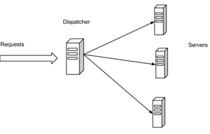
Today’s internet has a high, ever-growing volume of traffic. Some online services, such as web sites and social networks, have to be able to cope with millions of requests per day. The need to improve web server capacity is often faced by administrators. A popular solution to increase capacity and improve reliability of web services is to have multiple servers working collectively as a single web resource. Online services are often replicated on multiple servers, providing greater capacity and increased reliability. This collection of servers can be known as a distributed web server, a server cluster, or a web farm [34]. In this distributed architecture, incoming requests are routed among the various server nodes in a user-transparent way.
To effectively utilize the resources of a cluster of servers, a load balancing scheme must be adopted. The chosen scheme consists of the entity doing the load balancing and the algorithm used to decide which server to send each request to. A dispatcher-based load balancing approach is characterized by having a separate entity — the dispatcher — deployed at the network’s ingress point, receiving the incoming requests and distributing them among the servers [6], as seen in Figure 2.3. A specialized network routing device, called a load balancer, typically materializes the dispatcher. The load balancer acts as a front-end for the server cluster, and runs a scheduling algorithm to make decisions regarding the distribution of load among the servers in the cluster. The algorithm plays an important part in the effectiveness of this distributed solution, since the choice of the right server to assign each request can increase cluster throughput and decrease the mean response time.
Load balancing is a technique used to evenly distribute workload amongst a collec-tion of resources, in order to get optimal resource utilizacollec-tion, minimum response time,
Chapter 2. Related Work 14
maximum throughput and avoid overload. In a typical dispatcher-based approach the server cluster is presented to the clients as a single virtual IP address, or IP alias. This is typically the address of a dispatcher that acts as a centralized scheduler and controls all routing decisions of all client requests. An example communication pattern in this approach would be: 1) a client sends a request to the IP address alias for some online service; 2) the request reaches the dispatcher; 3) the dispatcher selects the server that will service the request using some scheduling policy, and forwards the request to the chosen server in the cluster; 4) the chosen server handles the request and replies to the client. This distributed architecture allows a service to be easily scalable, since it is possible to add additional server machines to augment the performance of the service. Another benefit is service availability. An appropriate scheduling algorithm can provide the service with fault resilience, allowing machines to leave the cluster due to failure or maintenance, with a graceful degradation of performance [34].
2.2.1
Current Load Balancing Solutions
Today’s dispatcher-based load balancing solutions are accomplished using a vendor-specific network routing hardware (the dispatcher). These components have become essential in modern networks, and have evolved to provide other functionalities besides load balanc-ing, like caching and some network security features.
However, there are some disadvantages with this approach. Dedicated load balanc-ing hardware can be expensive (typically several thousand dollars). This can be an even greater burden if a service/network needs more than one, as is common. Furthermore, dispatchers run vendor software that implements a rigid choice of policies, and have lim-ited customizability [39]. It can be impossible to tailor scheduling policies to a particular need, and specialized administration may be required. On unstructured networks, such as a WAN, it can be hard to know what the best locations for the dispatchers are in order to effectively partition network load.
An important limitation of current dispatcher-based approaches is that the load can only be partitioned between the servers; dispatchers cannot choose the path the requests follow. They are forced to use the path imposed by the network. This can be a relevant disadvantage when there are multiple paths to a resource. This is a disadvantage we can tackle using SDN. Since we have full control over the network, we have the capability of not only choosing the destination of traffic but also the path it takes.
2.3
Emulating Software-Defined Networks
In order to evaluate our network control application, we opted to use a network emu-lator. The tool we use to make such emulations is Mininet Hi-Fi [18], an extension of Mininet [23].
Chapter 2. Related Work 15
2.3.1
Mininet
Mininet is a container-based emulator, employing lightweight OS-level containers that share a single kernel. It allows for the rapid prototyping of large networks on the con-strained resources of a single machine [18]. Mininet differs from other emulators em-ploying lightweight virtualization in its support of Software-Defined Networks. A con-sequence of an SDN architecture is that the functionality of the network can be defined after it has been deployed. New features can be added in software, without modifying the switches. Systems prototyped on Mininet support this paradigm. Mininet has been used as a prototyping environment in just about all SDN-related work, being now the de facto emulator used in such projects.
Current available prototyping environments have their pros and cons. Special-purpose test beds for networking can be very realistic, but they are costly to build and maintain, have practical resource limitations and may lack the flexibility to support experiments with custom topologies or behavior. The high cost alone makes it beyond the reach for most researchers [23]. Simulators, such as NS-2 [28], are appealing because they can run on a single machine. However, they lack realism. Their models for hardware, pro-tocols and traffic generation may raise fidelity concerns. Moreover, the code created on the simulator is not the same code that would be deployed on a real network, and they are not interactive. One could envision a solution with a network of virtual machines, having a virtual machine per network element and host. However, virtual machines are too heavyweight, limiting the scale of such a network to just a handful of switches and hosts.
Emulators, nonetheless, can obtain the best of both worlds. Like test beds, emula-tors run real code with interactive network traffic; and like simulaemula-tors, they support ar-bitrary topologies with low cost. Furthermore, emulator code can be “shrink-wrapped” and ported to a virtual machine, allowing one to effortlessly share their experiments [18]. Since Mininet preserves switch, application and script semantics between emulation and hardware, an idea that works on Mininet can be deployed on a real production network for validation or general use.
However, emulators may not provide adequate performance fidelity for experiments. As CPU resources are multiplexed in time by the scheduler, there is no guarantee that a host ready to send a packet will be scheduled immediately, or that virtual software switches will transmit data at the same rate as their physical counterparts. This is due to background loads that affect the performance of virtual nodes, leading to unrealistic re-sults. Infidelity may arise when multiple processes execute serially on the available cores, rather than in parallel as in physical hosts and switches. Unlike simulators, Mininet runs in real time and does not pause a host’s CPU clock. Therefore, events such as transmit-ting a packet or finishing a computation are susceptible to delays, due to serialization and background system load [18].
Chapter 2. Related Work 16
Mininet’s original architecture uses lightweight OS-level virtualization to emulate net-work elements. It makes use of Linux containers, a virtual system mechanism built on top of the kernel. It provides a virtual environment that has its own network namespace. A virtual network is created by placing hosts in a separate container (with a separate network namespace) and connecting them with virtual Ethernet pairs.
By using lightweight virtualization, Mininet can scale to hundreds of nodes and still maintain interactive performance. It was shown in [23] that networks with hundreds of switches can be started in tens of seconds. Topologies with a significant number of switches and hosts cannot fit in memory using system virtualization. Such large networks can be emulated on Mininet because it virtualizes less and shares more: the file system, user and process spaces, kernel devices and libraries are shared between containers and managed by the Operating System (OS).
Mininet provides a Python API that allows the creation of custom topologies. Switches, hosts, links and controllers can be defined and custom-tailored in a few code lines of Python.
The main problem of the original Mininet is that it does not provide any assurance of performance fidelity, because it does not isolate the resources used by virtual hosts and switches.
2.3.2
Mininet Hi-Fi
Mininet Hi-Fi attempts to accurately emulate and reproduce experiments limited by net-work resource constraints on a netnet-work of hosts, switches and links. This is done by carefully allocating and limiting host CPU and link bandwidth, and then monitoring the experiment to ensure the emulator is operating within the limits imposed, producing re-alistic results [18]. Thus, Mininet Hi-Fi extends the original Mininet architecture, adding mechanisms for performance isolation, resource provisioning and monitoring for perfor-mance fidelity.
Mininet Hi-Fi implements CPU and network bandwidth limits using OS-level features in Linux. As in Mininet, it uses control groups, or cgroups, to group processes together (belonging to a container/virtual host). It then enforces limits and isolation on the resource usage of each cgroup. CPU bandwidth is limited by enforcing a maximum time quota for a cgroup within a given period of time. Traffic control is exerted using the tc command, which allows the configuration of network link properties, such as bandwidth, delay, and packet loss.
Resource provisioning is accomplished by splitting the CPU among containers, with some margin to handle packet forwarding. Since the exact CPU usage for packet for-warding varies (with path length, lookup complexity and link load), it is hard to know in advance the correct configuration for an experiment. It is up to the experimenter to allocate link speeds, topologies and CPU slices based on an estimated demand.
Chapter 2. Related Work 17
Mininet Hi-Fi relies on the monitoring of the performance fidelity to help verify if an experiment is operating realistically. Measuring the inter-dequeue times of packets monitors link and switch fidelity. As links run at a fixed-rate, packets should leave at predictable times whenever the queue is non-empty. To monitor host fidelity, the CPU idle time is observed. CPU bandwidth limiting ensures that no virtual host receives excessive CPU time, but not whether each virtual host is receiving sufficient time to execute its workload. The presence of idle time implies that a virtual host is not starved for CPU resources, and the absence of idle time is conservatively assumed to indicate that fidelity has been lost and the experiment should be reconfigured [18].
Mininet Hi-Fi is ideal for experiments that have network constraints, that is, are lim-ited by network properties such as link bandwidth, rather than other system properties such as memory latency, and have aggregate resource requirements that would fit within a single modern machine. It is therefore a good fit for experiments that have modest resource requirements [18].
2.4
Final Remarks
This chapter provided a detailed description of the key concept of our work, SDN. We have seen how the separation of the control and data planes is achieved, and the inner workings of the controller software we will use to build of our SDN load balancer ap-plication. We have also explained what load balancing is, and how it is accomplished in current networks. As our choice in prototyping environment lied in Mininet Hi-Fi, we have justified that choice, and detailed how this emulator achieves its goals.
Given the background information provided in this chapter, we are now able to detail how a load balancer application can be built in a Software-Defined Network. In the next chapter we will describe how we have built our load balancing solution, as well as its scheduling algorithms.
Chapter 3
Load Balancing in SDN
Built as an application on top of a controller, load balancing behavior can be achieved without the need for expensive commercial hardware. Due to the extent of the network control allowed in a Software-Defined Networking architecture, it is possible to augment a load balancing scheduling policy to consider not only server load, but also network link load as well, as seen in previous work [19].
3.1
The Load Balancer Application
We have created a load balancer as an application built on top of the POX controller. As an OpenFlow controller, POX is connected to all the OpenFlow-enabled switches in the network. It treats applications as modules that can be loaded when it starts. These modules listen for and handle events triggered by POX in result of the switch’s behavior. The application is built by listening to specific events, and enforcing a set of network actions to be executed by the switches.
Message Description
Flow Modification Edits the flows on a flow table. We use it to add an entry to the flow table, but it can be used to edit or delete a flow entry. Statistics Request Requests statistics from the switches. We use it to request flow
table statistics, but it can be used for port, queue and switch statistics, amongst others.
Set Configuration Edits OpenFlow configuration options on a switch. Table 3.1: The OpenFlow messages used in our application.
Chapter 3. Load Balancing in SDN 20
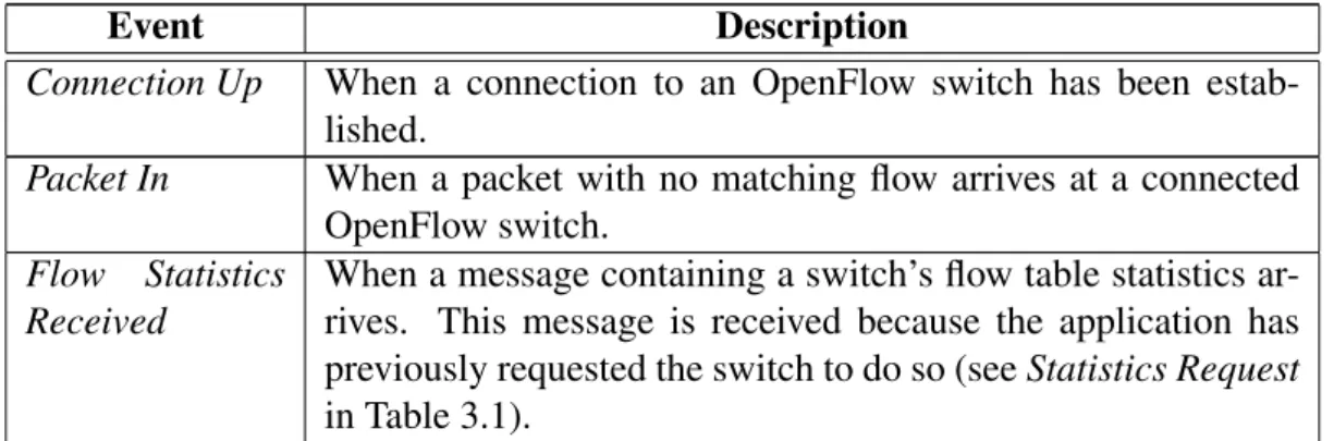
Event Description
Connection Up When a connection to an OpenFlow switch has been estab-lished.
Packet In When a packet with no matching flow arrives at a connected OpenFlow switch.
Flow Statistics Received
When a message containing a switch’s flow table statistics ar-rives. This message is received because the application has previously requested the switch to do so (see Statistics Request in Table 3.1).
Table 3.2: The OpenFlow events our application handles.
OpenFlow’s API is extensive [29]; however, we are only interested in a handful of operations. As seen before, the controller and the switches communicate through a secure channel. The controller exerts the application’s actions on a switch by sending it special-purpose OpenFlow messages, and presents the application with switch data triggering OpenFlow events. OpenFlow events contain attribute objects that hold the respective switch’s information and the OpenFlow message that triggered the event. For our pur-poses, we need to consider three OpenFlow messages, and need to listen to three events only, as reported in Tables 3.1 and 3.2, respectively.
The default action an OpenFlow switch will take upon receiving a packet whose header does not match any flow entry is to send it to the controller. So, when a switch receives a new packet, it will trigger a Packet In event. Our application will then run the respective event handler. It installs flow entries on the relevant switches (by sending a Flow Modificationmessages), triggering the switches to send the packet on its path un-til it reaches its destination. Subsequent packets belonging to the same connection will match on these flow table entries installed. No controller action is therefore needed (as long as packets keep matching on flow entries). These steps will be reviewed with greater detail in subsequent sections.
When the application needs to request flow table information, it instructs the controller to send a Statistics Request message to the switches. When it receives the reply from the switch, the controller will trigger a Flow Statistics Received event. The load balancer, having registered to listen for this event, collects the information it requested. We will later see how our load balancer application uses this information.
Connection Up events and Set Configuration messages occur in the startup stage of the application only. A switch can be configured to send along a specific number of the first bytes of an unmatched packet when communicating this occurrence to the controller. We use Set Configuration to configure the switches to send the whole packet. While this exerts additional overhead in some scenarios, it is negligible in ours.
Chapter 3. Load Balancing in SDN 21
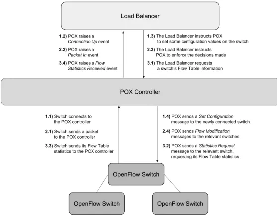
Figure 3.1: Communication between controller, switches and the load balancer.
A view of the communication between switches, controller and load balancer appli-cation, as these various events and messages are used, can be seen in Figure 3.1. We note that the three occurrences depicted in this figure are not presented in any temporal order. For example, while it is necessary for a switch to connect to the controller in order to be recognized and used by the application (messages 1.x in the figure), there is no relation between the arrival of new packets and the request for switch information (i.e., messages 2.x and 3.x can occur in different orders).
3.1.1
Flows
Flow entries installed in the switches must be made so that all packets from one connec-tion match on them. This is due to the fact that several web services require servers to use stored client information in order to effectively service a request. This makes it impera-tive that all packets pertaining to a request be sent to the same server. For our purposes, we define connection as a TCP connection. As explained in the previous section, we can build flow entries that match on a single field (all other fields being wild cards), or on a set of fields. A TCP connection can be characterized by the 4-tuple hsource IP address, destination IP address, source TCP port, destination TCP porti. When creating flows, we construct them so that packets match on these four fields.
Chapter 3. Load Balancing in SDN 22
Flows have a time-to-live period. They can be configured to expire when we wish them to do so. Hard and soft timeouts can be attributed to a flow entry. A hard timeout will trigger a switch to delete the flow entry from its flow table after an imposed amount time has passed. A soft timeout will have a flow entry deleted only when the flow has been inactive for a certain amount of time. Inactivity in a flow entry means having no packets matching on it. On our setup, flow entries pertaining client-server communication have a soft timeout of 30 seconds, and have no hard timeout.
Each flow entry is associated with an action. In our setting we need to consider two. First, to route packets to their destination, the action the switches take is to forward the received packet to the egress port leading to the next hop in the path. Second, to translate from the virtual address to the effective server address that will treat the request (recall Section 2.2) we need to change certain fields of a packet, as a server host machine will only acknowledge a packet to be destined to it when its MAC and IP addresses are the same as the packet’s destination MAC and IP addresses. Since clients do not know which server will service their request, the load balancer must write the target server’s MAC/IP on these fields. The destination MAC/IP addresses of packets will then be the same as those of the chosen server.
3.1.2
Routing
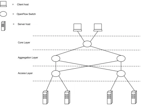
As said before, the POX controller provides management applications with a network view. This dynamic view keeps changing as network events occur, and is a result of the controller’s observations. In a typical network, control applications would be aware of topology changes, graciously accommodating nodes entering and leaving the network. Routing paths would be calculated dynamically, commonly by a routing application run-ning on the controller. In such a scenario, our load balancer would use this dynamic routing information when building up the path choices for a resource. However, since routing is not in the scope of our work, we have opted to define the network topology and routing in a static way. The network topology remains unchanged throughout the experiments, and so do the available routing paths.
In our implementation, topology information is read from a file. This file provides our application with knowledge on server and switch’s names, IP and MAC addresses, and switch’s Data Path Identifiers (DPIDs) (a unique switch identifier). The names are useful to identify each node (switch or server) when running the application.
The file also provides the load balancing application with routing information. The application reads from the file details about every switch’s ports, and to which nodes they lead to. This is what allows the load balancer to construct the available paths between nodes, and present the available choices when choosing a path to a server.
Chapter 3. Load Balancing in SDN 23
3.2
Load Balancing
After presenting the generic details of our application, we now proceed to explain how it distributes client’s requests among the servers.
Each of the replicated servers has its own IP address in the network. However, the collection of servers is viewed by the client as one single entity that provides some web service. In our case, we assume the service to be a traditional web server, in which clients issue HyperText Transfer Protocol (HTTP) requests and the server sends a response. This web service responds to a single IP — an IP alias — and clients seeking to use the service will send requests to this IP.
When a client sends a request to the web service’s IP alias, the switch connected to the client will raise a Packet In event on the controller if the respective packet header informa-tion does not match on any of the switch’s flow entries. As explained before, this event is triggered by the request’s first packet, and the load balancer handles it. The load balancer will then choose a server from the collection of servers using a particular scheduling pol-icy. In certain cases it will also choose a specific path for the server. After the decision is made, the controller then installs flow entries on each switch’s flow table down the chosen path. When the server response’s first packet arrives at the switch connected to the server, it triggers another Packet In event, and the load balancer installs flow table entries for the reverse path of the reply packets in the flow table.
3.2.1
Handling Packet In Events
A switch raises a Packet In event in three distinct situations:
1. When it receives the first packet of a request issued by a client — A packet is ruled to be the first of a client-initiated HTTP request if the load balancer does not have a hclient IP, client TCP porti pair stored for the packet header on its state. In this circumstance, the load balancer chooses a server and a path to the server, and stores this information in its state. How the load balancer makes this choice is explained in Section 3.3. Finally, a flow entry is installed in the flow table of every switch of the path. On the ingress switch that receives client traffic, the flow entry installed will not only enforce the action of forwarding the packet to the port leading to the next hop on the path, but will also rewrite the packet’s destination IP and MAC addresses to that of the chosen server. Subsequent flow entries (on all other switches) will need only to route the packet down its path; no field rewriting is necessary.
2. When the first packet of a server reply is received — When a client request reaches a web server, the server will in turn issue a response. The response packets will not match on flow table entries previously installed for the client-to-server path. Just as
Chapter 3. Load Balancing in SDN 24
happens for the client-to-server communication path, the first packet of the server response will trigger a Packet In In event. This packet’s fields will be the reverse of their respective client-to-server counterparts. If for the pair hdestination IP address, destination TCP porti a hserver, path to serveri pair is stored as load balancer’s state, the packet is from the server’s response. Flow table entries are installed for the path retrieved from the load balancer’s state, but in the reverse order. The first hop switch’s flow entry will have an extra action to rewrite the source IP and MAC addresses to that of the web service’s IP and MAC alias.
3. When the packet received is a packet pertaining to an ongoing connection that ar-rives at a switch before the respective flow table entry is installed — Flow entries are installed into the OpenFlow switches by the controller. However, there is no strict time guarantee as to when this happens. It is possible for a packet to reach a switch before the matching flow entry is installed. Because the switch does not yet know what to do with it, it triggers a Packet In event. As the load balancer already knows the route this packet will traverse (it has already made the decision, other-wise the packet would not be “in-flight”) it can install the flow accordingly. Hence, when a packet arrives before its respective flow entry, the switch is instructed by the load balancer to forward the packet to the next hop in the path retrieved from the load balancer’s state. Packets arriving at a switch before their respective flow entry is installed can occur either in the client-to-server path or the server-to-client path. Whichever the case, the load balancer determines the next hop, and instructs the switch to forward the packet to its correct egress port.
For our scenario, the load balancer’s state is a data structure that, for each pair of client IP address and TCP port, stores the chosen server and the path to the server.
3.3
Scheduling Algorithms
We have explained the basic functionality of our load balancer application and how its decisions are enforced in the network. The scheduling decisions, which are at the heart of the load balancing behavior, will now be described.
Traditional load balancing solutions, as said before, balance load across server ma-chines. These solutions are oblivious to the path the data takes to get to the chosen server. Therefore, they cannot take advantage of a network topology that allows multiple paths to a host machine. Scheduling load between multiple paths can be particularly beneficial when certain links become congested, or when a path’s delay is higher than another. The sophisticated network control and management allowed in an SDN architecture makes it possible for our load balancer application to balance load not only across servers, but also choose the path the data takes to reach the chosen server.
![Figure 2.2: OpenFlow Switch’s Components. The flow table is managed by a remote controller using the OpenFlow protocol, via a Secure Channel [25].](https://thumb-eu.123doks.com/thumbv2/123dok_br/19204554.955329/29.892.213.673.116.254/figure-openflow-switch-components-controller-openflow-protocol-channel.webp)
![Table 2.1: An example illustration of an OpenFlow-Enabled Switch’s flow table [30].](https://thumb-eu.123doks.com/thumbv2/123dok_br/19204554.955329/30.892.130.765.145.305/table-example-illustration-openflow-enabled-switch-flow-table.webp)