Architecture, Services and Protocols
for CRUTIAL
Anas Abou El Kalan, Amine Baina, Hakem Beitollahi,
Alysson Bessani, Andrea Bondavalli, Miguel Correia,
Alessandro Daidone, Wagner Dantas, Geert Deconinck,
Yves Deswarte, Henrique Moniz, Nuno Neves, Paulo Sousa,
Paulo Verissimo
DI-FCUL
TR–09–5
Março 2009
Departamento de Informática
Faculdade de Ciências da Universidade de Lisboa
Campo Grande, 1749-016 Lisboa
Portugal
Technical reports are available athttp://www.di.fc.ul.pt/tech-reports. The files are stored in PDF, with the report number as filename. Alternatively, reports are available by post from the above address.
Project Acronym:
CRUTIAL
Start date of the project:
01/01/2006
Duration: 36 months
Deliverable no.:
D18
Title of the deliverable: Architecture, Services and
Protocols for CRUTIAL
Project co-funded by the European Commission within the Sixth
Frame-work Programme (2002-2006)
Contractual Date of Delivery to the CEC: 13/03/2009
Actual Date of Delivery to the CEC: 13/03/2009
Organisation name of lead contractor for this deliverable FCUL
Editor(s): Nuno Neves2, Paulo Verissimo2
Author(s): Anas Abou El Kalam4; Amine Baina4; Hakem Beitollahi5; Alysson Bessani2; Andrea
Bondavalli3: Miguel Correia2; Alessandro Daidone3; Wagner Dantas2; Geert Deconinck5; Yves
Deswarte4; Henrique Moniz2; Nuno Neves2; Paulo Sousa2; Paulo Verissimo2;
Participant(s): (1) CESI-R; (2) FCUL; (3) CNR-ISTI; (4) LAAS-CNRS; (5) KUL; (6) CNIT
Work package contributing to the deliverable: WP4
Nature: R
Dissemination level: PU
Version: 004
This document describes the complete specification of the architecture, services and pro-tocols of the project CRUTIAL. The CRUTIAL Architecture intends to reply to a grand challenge of computer science and control engineering: how to achieve resilience of critical information infrastructures (CII), in particular in the electrical sector.
In general lines, the document starts by presenting the main architectural options and com-ponents of the architecture, with a special emphasis on a protection device called the CRUTIAL Information Switch (CIS). Given the various criticality levels of the equipments that have to be protected, and the cost of using a replicated device, we define a hierarchy of CIS designs incre-mentally more resilient. The different CIS designs offer various trade offs in terms of capabilities to prevent and tolerate intrusions, both in the device itself and in the information infrastructure.
The Middleware Services, APIs and Protocols chapter describes our approach to intrusion-tolerant middleware. The CRUTIAL middleware comprises several building blocks that are or-ganized on a set of layers. The Multipoint Network layer is the lowest layer of the middleware, and features an abstraction of basic communication services, such as provided by standard pro-tocols, like IP, IPsec, UDP, TCP and SSL/TLS. The Communication Support layer features three important building blocks: the Randomized Intrusion-Tolerant Services (RITAS), the CIS Com-munication service and the Fosel service for mitigating DoS attacks. The Activity Support layer comprises the CIS Protection service, and the Access Control and Authorization service. The Access Control and Authorization service is implemented through PolyOrBAC, which defines the rules for information exchange and collaboration between sub-modules of the architecture, cor-responding in fact to different facilities of the CII’s organizations. The Monitoring and Failure Detection layer contains a definition of the services devoted to monitoring and failure detection activities.
The Runtime Support Services, APIs, and Protocols chapter features as a main component the Proactive-Reactive Recovery service, whose aim is to guarantee perpetual correct execution of any components it protects.
Table of Contents 1
List of Figures 2
1 Introduction 5
2 Architecture 8
2.1 Fundamental Architectural Options . . . 9
2.2 Hierarchy of CRUTIAL Information Switches . . . 11
2.3 Middleware . . . 15
3 Middleware Services, APIs and Protocols 18 3.1 Multipoint Network . . . 18
3.1.1 IP – Internet Protocol . . . 18
3.1.2 IPSec – Internet Protocol Security . . . 19
3.1.3 UDP and TCP . . . 20
3.1.4 SSL – Secure Socket Layer . . . 22
3.2 Communication Support . . . 23
3.2.1 Randomized Intrusion-Tolerant Services . . . 23
3.2.2 CIS Communication Service . . . 37
3.2.3 Fosel for Mitigating DoS Attacks . . . 50
3.3 Activity Support . . . 67
3.3.1 CIS Protection Service . . . 67
3.3.2 Access Control and Authorization . . . 76
3.4 Monitoring and Failure Detection . . . 93
3.4.1 The Diagnosis Framework . . . 93
3.4.2 Correlation of Diagnosis Information . . . 95
4 Runtime Support Services, APIs and Protocols 105
4.1 CIS Proactive-Reactive Recovery . . . 105
4.1.1 Overview . . . 105
4.1.2 Model of the System . . . 106
4.1.3 Service Description and Interface . . . 107
4.1.4 Service Protocols . . . 110
4.1.5 Integrating PRRW in the CIS . . . 114
5 Conclusions 117
2.1 CRUTIAL overall architecture (WAN-of-LANs connected by CIS, P processes
live in the several nodes) . . . 9
2.2 Example mapping of part of an infrastructure to the WAN-of-LANs architecture. 10 2.3 Non-intrusion-tolerant CIS design. . . 12
2.4 Intrusion-tolerant CIS design. . . 13
2.5 Intrusion-tolerant & self-healing CIS design. . . 15
2.6 CRUTIAL middleware. . . 17
3.1 The RITAS protocol stack. . . 23
3.2 Generic channel table T of node p (channel instance Tqin detail). . . 43
3.3 CIS-CS architecture. . . 46
3.4 The Fosel architecture. . . 53
3.5 Applying Fosel into the CRUTIAL architecture. . . 59
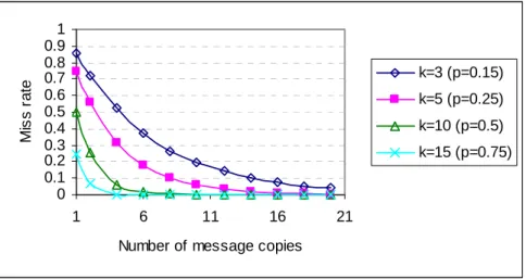
3.6 Miss rate vs. number of message copies (20 senders simultaneously). . . 61
3.7 Miss rate vs. number of selected queues (20 senders simultaneously). . . 62
3.8 Miss rate vs. attack rate (for different values of selected queues). . . 63
3.9 Miss rate vs. attack rate (for different values of message copies). . . 63
3.10 Compare Fosel, SOS and a straightforward filter (deadline miss rate vs. attack rate for different values of selected queues). . . 64
3.11 Compare Fosel, SOS and a straightforward filter (deadline miss rate vs. attack rate for different values of message copies). . . 64
3.12 DoS attack in the static case. . . 65
3.13 DoS attack in the dynamic case. . . 66
3.14 DDoS attack in the dynamic case. . . 66
3.15 An intrusion-tolerant CIS architecture. . . 69
3.16 Self-healing CIS architecture. . . 74
3.17 Modeling Permissions. . . 81
3.18 Modeling Prohibitions. . . 82 3
3.19 Modeling Obligations. . . 82
3.20 Modeling Conflicts. . . 83
3.21 Exchanges Signals in Load Shedding Scenario. . . 84
3.22 Created Web Services in Load Shedding Scenario. . . 85
3.23 Using PolyOrBAC in Load Shedding Scenario. . . 85
3.24 OrBAC rule for the arming request at TS CC side. . . 86
3.25 OrBAC rule for the arming request/order at DSCC side. . . 86
3.26 OrBAC rule for the arming order at DSSS side. . . 87
3.27 TSCC-WS1-arming automata. . . 87 3.28 DSCC-WS1-arming automata. . . 88 3.29 DSCC-WS2-arming-order automata. . . 88 3.30 DSSS-WS2-arming-order automata. . . 89 3.31 TSCC-WS3-loadshedding automata. . . 89 3.32 TSSS-WS3-loadshedding automata. . . 90 3.33 TSSS-WS4-loadshedding automata. . . 90 3.34 DSSS-WS4-loadshedding automata. . . 90 3.35 DSCC-WS5-reintegration automata. . . 91
3.36 The diagnosis framework identifying the chain constituted by the monitored com-ponent, the error detection mechanism and the diagnosis mechanism. . . 94
3.37 Data fusion: conceptual schema. . . 96
4.1 Relationship between the rejuvenation period TP, the rejuvenation execution time TD, and k. . . 108
4.2 PRRW architecture. . . 108
4.3 Recovery schedule (in an Si j or Risubslot there can be at most k parallel replica recoveries). . . 110
1
Introduction
The largely computerized nature of critical infrastructures on the one hand, and the perva-sive interconnection of systems all over the world, on the other hand, have generated one of the most fascinating current problems of computer science and control engineering: how to achieve resilience of critical information infrastructures. In project CRUTIAL, we are concerned with the susceptibility of the latter to computer-borne attacks and faults, i.e., with the protection of these infrastructures. We propose an architecture and a set of techniques and algorithms aiming at achieving resilience to faults and attacks in an automatic way. Although we focus on the com-puter systems behind electrical utility infrastructures as an example, the architecture we propose is generic and may come to be useful as a reference for modern critical information infrastructures.
It is worthwhile recapitulating some of the reasoning behind the blueprint of this architec-ture, recently published in [114, 115]. Although inspired by previous intrusion-tolerant system architectures, the CRUTIAL architecture was largely influenced by two facts. Firstly, the fact that Critical Information Infrastructures (CII) feature a lot of legacy subsystems (controllers, sensors, actuators, etc.). Secondly, the fact that conventional security and protection techniques can bring serious problems, when directly applied to CII controlling devices, by preventing their effective operation. Although they are very practical problems, we will show ahead that they yielded in fact very interesting research challenges.
Another relevant fact was that our belief that the crucial problems in critical information infrastructures lie with the forest, not the trees, has been confirmed everyday as new incidents have occurred. That is, the problem is mostly created by the generic and non-structured network interconnection of CIIs, which bring several facets of exposure impossible to address at individual level. Whilst it seems today non-controversial that such a status quo brings a considerable level of threat, to our knowledge there had been no previous attempt at addressing the problem through the definition of a reference model of a critical information infrastructure distributed systems ar-chitecture. One which, by construction, would lay the basic foundations for the necessary global resilience against abnormal situations. Our conjecture was that such a model would be highly con-structive, for it would form a structured framework for (1) conceiving the right balance between prevention and removal of vulnerabilities and attacks; (2) achieving tolerance of remaining poten-tial intrusions and designed-in faults; and (3) enabling adaptation and self-awareness mechanisms to overcome unforeseen situations.
Finally, and in a related manner, we conjectured that any solution, to be effective, has to involve automatic control of macroscopic command and information flows, occurring essentially between the several realms composing the critical information infrastructure architecture (both intra- and inter-organizations), with the purpose of securing appropriate system-level properties, at organizational level. This has to be addressed, in an automatic way, through innovative access control models that understand the organizational reality, and are thus capable of translating the related high-level security policies into the adequate technical mechanisms such as access control matrices and firewall filter rule-sets.
of the project CRUTIAL. The definitions herein elaborate on the major architectural options and components established in the Preliminary Architecture Specification [83] and Preliminary Speci-fication of Services and Protocols [84], with special relevance to the CRUTIAL middleware build-ing blocks, and are based on the fault, synchrony and topological models defined in the previous documents. The document, in general lines, describes the generic aspects of the Architecture, the Middleware and the Runtime Support Services.
The Architecture chapter discusses the main options that were taken during the definition of the CRUTIAL Architecture. It also introduces several designs of a protection device called the CRUTIAL Information Switch (CIS). The CIS ensures that the incoming and outgoing traffic in/out of a protected LAN satisfies the security policy of the organization that manages the LAN. Given the various criticality levels of the CI equipment and the cost of using a replicated device, a hierarchy of CISs designs is proposed to offer incrementally more resilient solutions. The chapter ends with an overview of the CRUTIAL middleware, which is then next presented with more detail.
The Middleware chapter describes our approach to intrusion-tolerant middleware. The middleware organized in several layers, each one providing services to other layers or directly to the applications. The Multipoint Network layer is the lowest layer of CRUTIAL’s middleware, and features an abstraction of basic communication services, such as provided by standard protocols, like IP, IPsec, UDP, TCP and SSL/TLS.
The Communication Support layer features three important building blocks: the Random-ized Intrusion-Tolerant Services (RITAS), the CIS Communication service and the Fosel service for mitigating DoS attacks. The Randomized Intrusion-Tolerant Services (RITAS) are organized as a stack of randomized intrusion-tolerant protocols, supporting applications who depend on intrusion-tolerant broadcast and agreement. These protocols, being randomized, overcome the impossibility result in asynchronous settings established in [50] (also called the FLP result), but present a significant performance improvement over previous protocols of the same class. The CIS Communication service supports secure communication between CIS and, ultimately, be-tween LANs. It provides secure channels, multicast primitives, and probabilistic gossip-based information diffusion between CIS. In recent years DoS attacks have become one of the most seri-ous security threats to the Internet. Today Internet protocols have become an emerging technology for remote control of industrial applications, and as such, vulnerable to the same kind of attacks. We address the DoS problem with an overlay protection layer for DoS attacks on top of the normal infrastructure.
The Activity Support layer comprises the CIS Protection service and the Access Control and Authorization service. The CIS Protection service protects realms from one another, i.e., a LAN from another LAN or from the WAN, thus allowing us to deal both with outsider and in-sider threats. The Access Control and Authorization service is implemented through PolyOrBAC, which defines the rules for information exchange and collaboration between sub-modules of the architecture, corresponding in fact to different facilities of the CII. Each organization specifies its security policy according to OrBAC. As organizations are interconnected through CIS, each CIS regroups mechanisms to define security policy of systems that compose each LAN (local and collaboration policies), and it also regroups mechanisms for collaboration: to make these LANs
capable of collaboration and offering services to each other.
The Monitoring and Failure Detection layer is devoted to monitoring and failure detection activities. Diagnosis in Crutial should occur at different components at different architectural levels, and as such, the classical framework has been extended: several components need to be monitored and several deviation detection mechanisms need to be in place, errors observed in different components must be correlated. Likewise, given that we are dealing with a complex infrastructure, methods for distributed diagnosis are mandatory, with a distinction between local and global detection and diagnosis.
The Runtime Support chapter features as a main component, the Proactive-Reactive Re-covery Service, whose aim is to guarantee perpetual execution of any components it protects. In CRUTIAL we investigated limitations of existing approaches to intrusion-tolerant proactive recovery, and proposed a very complete scheme addressing them, which we named proactive-reactive recovery. Our first observation is that protecting oneself from timing attacks by using asynchronous models, and fulfilling periodic recoveries, are incompatible goals. To address this issue, we propose an innovative scheme based on a hybrid sync-asynchronous architecture, called proactive resilience. Our second observation is that one should allow correct replicas that detect or suspect that some replica is faulty, to accelerate the recovery of this replica. It is known that perfect Byzantine failure detection is impossible to attain in a general way. In consequence, deal-ing with imperfect failure detection is the most complex aspect of the proactive-reactive recovery service presented.
2
Architecture
The CRUTIAL architecture encompasses four aspects:
• Architectural configurations featuring trusted components in key places, which a priori in-duce prevention of some faults, and of certain attack and vulnerability combinations. • Middleware devices that achieve runtime automatic tolerance of remaining faults and
intru-sions, supplying trusted services out of non-trustworthy components.
• Trustworthiness monitoring mechanisms detecting situations not predicted and/or beyond assumptions made, and adaptation mechanisms to survive those situations.
• Organisation-level security policies and access control models capable of securing informa-tion flows with different criticality within/in/out of a CII.
Given the severity of threats expected, some key components are built using architectural hybridisation methods in order to achieve trusted-trustworthy operation [112]: an architectural paradigm whereby components prevent the occurrence of some failure modes by construction, so that their resistance to faults and hackers can justifiably be trusted. In other words, some special-purpose components are constructed in such a way that we can argue that they are always secure, so that they can provide a small set of services useful to support intrusion tolerance in the rest of the system.
Intrusion tolerance mechanisms are selectively used in the CRUTIAL architecture, to build layers of progressively more trusted components and middleware subsystems, from baseline un-trusted components (nodes, networks) [112]. This leads to an automation of the process of build-ing trust: for example, at lower layers, basic intrusion tolerance mechanisms are used to construct a trustworthy communication subsystem, which can then be trusted by upper layers to securely communicate amongst participants without bothering about network intrusion threats.
One of the innovative aspects of this work, further to intrusion tolerance, is the resilience aspect, approached through two paradigms: proactive-resilience to achieve exhaustion-safety [103], to ensure perpetual, non-stop operation despite the continuous production of faults and intrusions; and trustworthiness monitoring to perform surveillance of the coverage stability of the system, that is, of whether it is still performing inside the assumed fault envelope or beyond assumptions made [21]. In the latter case, dependable adaptation mechanisms are triggered.
Finally, the desired control of the information flows is partly performed through protection mechanisms using an adaptation of the organisation-based access control model (OrBAC) [1] for implementing global-level security policies. OrBAC allows the expression of security policy rules as high level abstractions, and the composition of the security policies of the organizations into one global policy.
The mechanisms and algorithms in place achieve system-level properties of the following classes: trustworthiness or resistance to faults and intrusions (i.e., security and dependability);
timeliness, in the sense of meeting timing constraints raised by real world control and supervision; coverage stability, to ensure that variation or degradation of assumptions remains within a bounded envelope; dependable adaptability, to achieve predictability in uncertain conditions; resilience, read as correctness and continuity of service even beyond assumptions made.
2.1
Fundamental Architectural Options
We view the system as a WAN-of-LANs, as introduced in [110]. There is a global inter-connection network, the WAN, that switches packets through generic devices that we call facility gateways, which are the representative gateways of each LAN (the overall picture is shown in Figure 2.1). The WAN is a logical entity operated by the CII operator companies, which may or may not use parts of public network as physical support. A LAN is a logical unit that may or may not have physical reality (e.g., LAN segments vs. Virtual LANs (VLANs)). More than one LAN can be connected by the same facility gateway. All traffic originates from and goes to a LAN. As example LANs, the reader can envision: the administrative clients and the servers LANs; the operational (SCADA) clients and servers LANs; the engineering clients and servers LANs; the PSTN modem access LANs; the Internet and extranet access LANs, etc.
C I S W A N L o c a l N e t w o r k F a c i l i t y F a c i l i t y C I S C I S L o c a l N e t w o r k C I S M o d e m s e r v e r P S T N I n t e r n e t C I S C I S h o s t i l e e n v i r o n m e n t N o d e N o d e N o d e N o d e N o d e N o d e
Figure 2.1: CRUTIAL overall architecture (WAN-of-LANs connected by CIS, P processes live in the several nodes)
The facility gateways of a CRUTIAL critical information infrastructure are more than mere TCP/IP routers. Collectively they act as a set of servers providing distributed services relevant to solving our problem: achieving control of the command and information flow, and securing a set of
W A N ( i n t e r n e t , p r i v a t e l i n k s , . . . ) C I S C I S c o r p o r a t e n e t w o r k C I S w o r k s t a t i o n s w e b s e r v e r p u b l i c s e r v i c e n e t w o r k d a t a a r c h i v e h i s t o r i a n n e t w o r k o p e r a t o r o p e r a t i o n g a t e w a y o p e r a t i o n n e t w o r k s u b s t a t i o n c o n t r o l n e t w o r k D i s t r i b u t i o n S y s t e m O p e r a t o r c e n t r e C I S s u b s t a t i o n s o t h e r e n t i t i e s
Figure 2.2: Example mapping of part of an infrastructure to the WAN-of-LANs architecture. necessary system-level properties. CRUTIAL facility gateways are called CRUTIAL Information Switches (CIS), which in a simplistic way could be seen as sophisticated circuit or application level firewalls combined with equally sophisticated intrusion detectors, connected by distributed protocols.
This set of servers must be intrusion-tolerant, prevent resource exhaustion providing per-petual operation (i.e., can not stop), and be resilient against assumption coverage uncertainty, providing survivability. The services implemented on the servers must also secure the desired properties of flow control, in the presence of malicious traffic and commands, and in consequence be themselves intrusion-tolerant.
An assumed number of components of a CIS can be corrupted. Therefore, a CIS is a logical entity that has to be implemented as a set of replicated physical units (CIS replicas) according to fault and intrusion tolerance needs. Likewise, CIS are interconnected with intrusion-tolerant protocols, in order to cooperate to implement the desired services. The CIS boxes in the figure represent these intrusion-tolerant, replicated, logical CIS.
An example WAN-of-LANs. The WAN-of-LANs model is very abstract so in this section we
use it to represent a small part of a distribution power grid. This example is inspired in a testbed
of the CRUTIAL project presented in [37]1, and the corresponding scenario in [45].
Figure 2.2 presents a Distribution System Operator (DSO) centre. This centre includes 1See Section 3.1.1 of that document.
several networks and is connected to the substations through the substation control network (bot-tom). This network is connected to the substations through the (logical) WAN, which can be the Internet, a set of private links, VLANs or other type of network. The DSO centre includes the corporate network (top), the public service network were services like web servers are placed (middle), the data historian network were historical information about the infrastructure is stored (top right), and the operation network were operators monitor and control the power generation infrastructure (right). All these networks are modeled as (logical) LANs and are connected by CIS, that protect them from one another and, especially, from the Internet/WAN.
2.2
Hierarchy of CRUTIAL Information Switches
The protection of a LAN is made by a CIS device that provides two basic services: • the Protection Service (PS) and
• the Communication Service (CS).
The PS ensures that the incoming and outgoing traffic in/out of the LAN satisfies the security policy of the organization that manages the LAN. CS supports secure communication between CIS and, ultimately, between LANs. The CS provides secure channels, reliable and atomic multicast primitives, and probabilistic gossip-based information diffusion between CIS.
Give the various criticality levels of the CI equipment and the cost of using a replicated device, it is worth defining a hierarchy of CISs designs incrementally more resilient. Next we present this hierarchy and, for each design, we point out what it offers, its cost and limitations.
Notice that more details about the CIS Protection and Communication Services are pro-vided respectively in Section 3.3.1 and 3.2.2.
Non-Intrusion-Tolerant CIS Figure 2.3 depicts the design of a non-intrusion-tolerant CIS. The
non-intrusion-tolerant CIS is the cheapest design because it only requires one machine just as any classical firewall. Nevertheless, it offers better protection than normal firewalls through the use of application-level policy enforcement and of a rich access control model. These characteristics reduce the probability of an attacker being able to construct a well-crafted message and deceive the CIS to let it go through. Although it is more difficult to mislead the CIS, an attacker may find a way of compromising the machine where the CIS is running (e.g., by exploiting a vulnerability of the operating system) and take control of CIS operation. Notice that the attacker may need days, weeks, or even months to find a vulnerability and deploy such an attack, but from what happened in the past we know that with a reasonable probability she will eventually have success in her quest.
Intrusion-Tolerant CIS To understand the rationale of the design of the intrusion-tolerant CIS,
Data Historian
Switch
PLC
Switch
Figure 2.3: Non-intrusion-tolerant CIS design.
and the LAN that we want to protect. Further assume that we wish to ensure that only the correct messages (according to the deployed policy) go from the non-trusted side, through the CIS, to the computers and/or devices in the protected LAN. A first difficulty to address is that traffic has to be received by all n replicas, instead of only 1 (as in a normal firewall), to allow every replica to participate in the decisions. A second problem is that up to f replicas can be faulty and behave malicious, both towards the other replicas as to the receiver computers (e.g., the SCADA controllers).
Our solution to the first problem is to use some device (e.g., an Ethernet hub) to broadcast the traffic to all replicas. These verify whether the messages comply with the security policy and do a vote, approving a message if and only if at least f + 1 different replicas are in favor. This guarantees that at least one correct replica thinks that the message should go through. An approved message is then transmitted by the CIS to the destination by a distinguished replica, the leader, so there is no unnecessary traffic multiplication inside the LAN.
Traditionally, intrusion-tolerant mechanisms address the second problem with masking protocols of the Byzantine type, which extract the correct result from the n replicas, despite f maliciously: basically, only results (or messages) that are supported by f + 1 replicas are accepted. Since a result must be sent to the computers in the protected LAN, this consolidation has to be performed either at the source or at the destination. The simplest and most usual approach implements a front-end at the destination host that accepts a message if: (1) f + 1 different replicas send it; or (2) the message has a certificate showing that f + 1 replicas approve it; or (3) the
message has a signature generated by f + 1 replicas using threshold cryptography2. This however
would require changes to the end hosts and the traffic in the protected LAN would be multiplied by n in certain cases (every replica would send the message), which is undesirable.
2Threshold cryptography is a form of cryptographic that allows to split a key among a set of parties and to define the minimum number of parties that are required to make useful things with the key (see [99]). Unfortunately, it can only be used in combination with public key cryptography schemes where different keys are used to encrypt and to decrypt, whereas IPSEC/AH uses the same key to produce and verify MACs.
Data Historian Hub PLC Hub W W W
Figure 2.4: Intrusion-tolerant CIS design.
Therefore, we should turn ourselves to consolidating at the source and transmit only one, but correct, message. What is innovative here is that the source-consolidation mechanism should be transparent to the protected LAN. Moreover, this has to be done with the following difficulty in mind – since a faulty replica (leader or not) has direct access to the LAN, it can send incorrect traffic to the protected computers, which can not distinguish between good and bad messages. This makes consolidation at the source a hard problem.
According to best practice recommendations from expert organizations and governments, the standard protocols that are expected to be generalized in SCADA/PCS systems will utilize
IPSECto secure the communications. Consequently, we can assume that the IPSEC
Authentica-tion Header (AH) protocol [66] will be available, and take advantage of it to design our soluAuthentica-tions.
The basic idea is that the protected computers will only accept messages with a valid IPSEC/AH
Message Authentication Code (MAC), which can only be produced if the message is approved by
f + 1 different replicas. However, IPSEC/AH MACs are generated using a shared key3 K and
a hash function, so it is not possible to use threshold cryptography. As the attentive reader will note, the shared key storage becomes a vulnerability point that can not be overlooked in a highly resilient design – there must be some secure component that stores the shared key and produces MACs. This requirement calls for a secure component in an otherwise Byzantine-on-failure en-vironment, which we will name as a secure wormhole [111]. The wormhole can be deployed as a set of local trustworthy components, one per replica, using technologies such as smart-cards or cryptographic boards. Figure 2.4 depicts the design of an intrusion-tolerant CIS.
This CIS design requires 2 f + 1 machines in order to tolerate f intrusions. Thus, the configuration presented in Figure 2.4 is able to tolerate one intrusion. Notice that such a design only makes sense if the different machines can not be attacked in the same way, i.e., they must not share the same set of vulnerabilities. In order to achieve this goal, each CIS replica is deployed in a different operating system (e.g., Linux, FreeBSD, Solaris), and the operating systems are configured to use different passwords and different services. In addition, each CIS replica is enhanced with a secure wormhole subsystem that stores a secret key and this key is used to produce a MAC for messages that are approved by at least f + 1 replicas. Given that the wormhole is secure, no malicious replica can force it to sign an unapproved message.
In practical terms, the intrusion-tolerant CIS is more difficult to compromise than the non-intrusion-tolerant version because an attacker will need to find vulnerabilities and deploy attacks against f + 1 diverse replicas and not just one. The task of compromising each replica may take days, weeks, or months, but attackers tend to be patient persons.
Intrusion-Tolerant and Self-Healing CIS The most resilient CIS design combines intrusion
tolerance with self-healing mechanisms in order to address the limitations explained in the pre-vious section. Self-healing is provided by a proactive-reactive recovery service that combines time-triggered periodic rejuvenations with event-triggered rejuvenations when something bad is detected or suspected [101].
Proactive recoveries are triggered periodically in every replica even if it is not compro-mised. The goal is to remove the effects of malicious attacks/faults even if the attacker remains dormant. Otherwise, if an attacker compromises a replica and makes an action that can be detected (e.g., sending a message not signed with the shared key K), the compromised replica is rejuve-nated through a reactive recovery. Moreover, the rejuvenation process of a (proactive or reactive) recovery does not simply restore replicas to known states, since this would allow an attacker to exploit the same vulnerabilities as before. The rejuvenation process itself introduces some degree of diversity to restored replicas (change operating system, use memory obfuscation techniques, change passwords, etc.), so that attackers will have to find other vulnerabilities in order to com-promise a replica. Figure 2.5 depicts the design of an intrusion-tolerant CIS with self-healing mechanisms.
This CIS design requires 2 f + k + 1 machines in order to tolerate f intrusions per recover-ing period (dictated by the periodicity of the proactive recoveries). The new parameter k represents the number of replicas that recover at the same time and its value is typically one. If this param-eter was not included in the calculation of the total number of required machines, the CIS could become unavailable during recoveries. Thus, the configuration presented in Figure 2.5 composed of 4 replicas is able to tolerate one intrusion while another is being rejuvenated. The length of the recovering period corresponds to the sum of the recovery time of each replica. In the experi-ments performed in our laboratory we were able to recovery each replica in less than 2.5 minutes, which means that the recovering period was less than 10 minutes when using 4 replicas [101]. In this scenario, an attacker would need to find vulnerabilities and deploy attacks against f + 1 = 2 replicas within 10 minutes, which seems to be difficult given that each recovery changes the set of vulnerabilities and the attacker has to restart her work. Moreover, we believe that the recovery
Data Historian Hub PLC Hub W W W W
Figure 2.5: Intrusion-tolerant & self-healing CIS design.
time of a replica can be reduced to less than one minute using readily available technologies such as solid state disks.
2.3
Middleware
We now observe the part of the system made of the WAN and all the CIS that interconnect all the internal LANs of the critical information infrastructure to the WAN (recall Figure 2.1).
We model this setting as a distributed system with N nodes (CIS). We use the weakest fault and synchrony models that allow to carry out the application tasks. So, we use the asyn-chronous/arbitrary model, which does not make any assumptions about either time needed to make operations and faults/intrusions that can occur, as a starting point, and strengthen it as needed. For example, by resorting to hybrid models using wormholes [111], and assuming some form of partial synchrony.
We assume that the environment formed by the WAN and all the CIS is hostile (not trusted), and can thus be subjected to malicious (or arbitrary or Byzantine) faults. On the other hand, LANs trust the services provided by the CIS, but are not necessarily trusted by the latter. That is, as we will see below, LANs have different degrees of trustworthiness, which the CIS dis-tributed protocols have to take into account. CIS securely switch information flows as a service to edge LANs as clients.
We assume that faults (accidental, attacks, intrusions) continuously occur during the life-time of the system, and that a maximum number of f malicious (or arbitrary) faults can occur within a given interval. We assume that services running in the nodes (CIS) cooperate through distributed protocols in such an environment. In consequence, these nodes have to be capable of tolerating fault/intrusions by employing replication techniques.
Some of the services running in CIS may require some degree of timeliness, given that SCADA implies synchrony, and this is a hard problem with malicious faults. We also take into account that these systems should operate non-stop, a hard problem with resource exhaustion (the continued production of faults during the life-time of a perpetual execution system leads to the inevitable exhaustion of the quorum of nodes needed for correct operation [103]).
LAN-level services A LAN is the top-level unit of the granularity of access control, regardless
of possible finer controls. It is also and correspondingly, a unit of trust or mistrust thereof. In fact, we are not concerned with what happens inside a LAN, except that we may attribute it a different levels of trust. For instance, if the LAN is a SCADA network, the level of trust is high, but if it is the access to the Internet then the level of trust is low.
Traffic (packets) originating from a LAN receive a label that reflects this level of trust, and contains access control information, amongst other useful things.
The trustworthiness of a label (that is, the degree in which it can or not be tampered with) can vary, depending on the criticality of the service. In the context of this document, and without loss of generality, we assume it is an authenticated proof of a capacity.
WAN-level services The collection of CIS implements a set of core services, aiming at achieving
the objectives we placed as desirable for a reference model of critical information infrastructure distributed systems architecture:
• Intrusion-tolerant information and command dissemination between CIS units, with authen-tication and cryptographic protection (broadcast, multicast, unicast).
• Pattern-sensitive information and command traffic analysis (behaviour and/ or knowledge-based intrusion detection) with intrusion-tolerant synchronisation and coordination between local Intrusion Detection Systems (IDSs).
• CIS egress/ingress access control based on LAN packet labels and/or additional mecha-nisms, implementing an instance of the global security policy.
The CIS middleware layers implement functionality at different levels of abstraction, as represented in Figure 2.6. As mentioned earlier, a middleware layer may overcome (through in-trusion tolerance) the fault severity of lower layers and provide certain functions in a trustworthy way.
M o n i t o r i n g a n d F a i l u r e D e t e c t i o n P h y s i c a l N e t w o r k M u l t i p o i n t N e t w o r k ( M N ) n m p C o m m u n i c a t i o n S u p p o r t S e r v i c e s ( C S ) A c t i v i t y S u p p o r t S e r v i c e s ( A S ) P r o a c t i v e R e c o v e r y + R e c o n f i -g u r a t i o n + D i v e r s i t y R u n ti m e E n vi ro n m e n t (t ru st e d f u n c ti o n s)
Figure 2.6: CRUTIAL middleware.
The lowest layer is the Multipoint Network module (MN), created over the physical infras-tructure. Its main properties are the provision of multipoint addressing, secure channels (IPsec, SSL, etc.), and management communications, hiding the specificities of the underlying network. The Communication Support Services module (CS) implements basic cryptographic primitives, Byzantine agreement, consensus, group communication and other core services. The CS mod-ule depends on the MN modmod-ule to access the network. The Activity Support Services modmod-ule (AS) implements building blocks that assist participant activity, such as replication management (e.g., state machine, voting), IDS and firewall support functions, access control. It depends on the services provided by the CS module.
The block on the left of the figure generically implements Monitoring and Failure Detec-tion. Failure detection assesses the connectivity and correctness of remote nodes, and the liveness of local processes. Trustworthiness monitoring and dependable adaptation mechanisms also re-side in this module, and have interactions with all the modules on the right. Both the AS and CS modules depend on this information.
The block to the right represents the support services. These include the usual operating system’s services, but also the trusted services supplied in support to the algorithms in the various modules: proactive recovery, reconfiguration, and diversity management.
3
Middleware Services, APIs and Protocols
The Middleware Services, APIs and Protocols chapter describes the intrusion-tolerant mid-dleware developed within the context of the project. The midmid-dleware comprises several layers, including the Multipoint Network, Communication and Activity Support, and Monitoring and Failure Detection.
3.1
Multipoint Network
The Multipoint Network (MN) is the bottom layer of CRUTIAL’s middleware (see Fig-ure 2.6). Its purpose is to offer a simple abstraction of the basic communication services provided by the underlying network infrastructure, which can then be utilized in an uniform way by the higher layers of the middleware. These services are said to be basic in the sense that they are implemented by standard protocols, like IP, IPsec, UDP, TCP and SSL/TLS. This section presents some of the protocols that can be integrated in the MN module, their services and APIs. The presentation is organized in terms of the two relevant layers of the TCP/IP reference model to which these protocols belong: Network and Transport. We skip the lowest layers for which there are many technologies and are too low level to be considered middleware: Ethernet (wired and wireless), SDH/ATM, Frame Relay, copper circuits, etc. Application layer protocols, like some protocols specific for critical infrastructures and industrial systems (MMS and ICCP), are also not described since they are seen at a higher level than the middleware.
3.1.1 IP – Internet Protocol
The main service provided by the Network layer in the Internet is routing data packets – datagrams – from the source host to the destination host. Hosts are interconnected by special nodes called routers that inspect the datagrams to forward – or route – them to the next router or the destination. The format of the datagrams is defined by the most widely used Network layer protocol in the Internet, the Internet Protocol (IP). Nowadays, IP underlies most communication networks around the world, including the Internet, corporate networks and even some control networks, so it is important to give some insight about it.
The most important data in an IP datagram are the source and destination host addresses. A host or, more precisely, each host’s network interface is identified by an IP address, which has 32 bits in IPv4, the current almost universally adopted version of IP. A shift to IPv6 is currently happening, although there is a high uncertainty about when it will end or even reach most of the Internet. IP also provides other services like fragmentation and reassembly of packets too big for the size of the packet transported by the physical network. IP does not ensure the reliability of the communication, i.e., datagrams can be dropped or duplicated.
multicast. This is important for CRUTIAL middleware since it involves multicast to several hosts, e.g., for several CIS. The multicasted datagram is delivered to all members of a certain group with the same guarantees given by the regular IP datagrams: it is not guaranteed to reach all members, it is not guaranteed to arrive intact to all members and it is not guaranteed to arrive in the same order to all members, relative to other datagrams. Hosts can join and leave the group at any time, i.e., group membership is dynamic. Multicast groups cannot span the whole Internet since not all routers support this functionality. Typically there are “islands” of routers in the Internet that support it.
The classical API to IP is the sockets API, originally defined in Berkeley Unix. Several versions appeared since them, starting in other Unixes, and up to MS-Windows and Java, to give some examples. However, sockets are not usually used to send IP datagrams directly – so called raw sockets – but instead at transport level to send data over UDP or TCP, so more details are provided below. IP multicast is also typically used below UDP, and the same reasoning applies to the API.
3.1.2 IPSec – Internet Protocol Security
Internet Protocol Security (IPSec) is an extension of IP that provides some level of security [67]. In its basic form, IP messages can be modified and its content read by anyone with access to the network, e.g., a hacker controlling a router. IPSec prevents this problem. IPSec has an important role in CRUTIAL since it is a basic mechanism to ensure security in the Network layer. IPSec is designed to enhance the security of IPv4, providing interoperable, high-quality, cryptographically-based security. It offers several services, such as access control, connectionless integrity, data origin authentication, protection against replays, confidentiality (through encryp-tion) and limited traffic flow confidentiality. Since these services are offered at the Network/IP layer, they can be used by any higher layer protocol, such as TCP, UDP, HTTP, etc. IPSec also supports negotiation of IP compression, motivated by the observation that encryption used within IPSec prevents effective compression by lower protocol layers.
IPSec is divided in two (sub)protocols, which may be applied alone or in combination with each other to provide the desired set of security properties at IP-level. The Authentication Header (AH) protocol provides connectionless integrity, data origin authentication, and an op-tional anti-replay service. The Encapsulation Security Payload (ESP) protocol provides payload confidentiality (using encryption) and limited traffic flow confidentiality. Optionally, it may also provide connectionless integrity, data origin authentication, and an anti-replay service.
Both AH and ESP are vehicles for access control, based on the distribution of crypto-graphic keys and the management of traffic flows relative to these security protocols. These pro-tocols support two different modes of operation. At Transport mode, IPSec essentially protects upper layer protocols (e.g., TCP). At Tunnel mode, the protocols are applied to tunneled IP pack-ets, i.e., the IP datagrams themselves are sent through a secure tunnel. IPSec allows the user or the system administrator to control the granularity at which a security service is offered, allowing,
for example, the creation of a single encrypted tunnel to carry all the traffic between two security gateways or a separate encrypted tunnel for each TCP connection between a pair of hosts com-municating across these gateways. IPSec can be configured to protect only the integrity of the communication (preventing modifications) or the integrity and the confidentiality of the traffic.
Most IPSec implementations do not have an API that can be used by applications to trans-mit secure data, other than the socket API used for IP, UDP or TCP. IPSec works at the operating system level, and typically can only be configured by the system administrator. A system admin-istrator can define the policy for IPSec on a host basis, determining the ways by which a host can connect securely to another.
3.1.3 UDP and TCP
Network-level IP solves the problem of end-to-end communication between hosts. How-ever, for implementing distributed applications, the problem that really has to be solved is slightly different: end-to-end communication between processes, since typically there are many processes running in each host. This is the problem solved by the Transport layer. In IP-based networks hosts are identified by IP addresses; inside a host, application are identified by ports (one or more), which are 16-bit numbers (range 0-65535). The standard Transport layer Internet protocols are the User Datagram Protocol (UDP) and the Transmission Control Protocol (TCP). Both protocols are used to support communication in critical infrastructures, so both are relevant for the CRUTIAL middleware.
UDP provides a datagram mode of packet-switched computer communication in an inter-connected set of computer networks. Applications can send messages to other programs with a minimum set of guarantees using UDP. The key characteristics of the protocol are: it is transaction oriented, the delivery of messages is not ensured, nor is the order of message arrival, and there might be duplication of messages. UDP in fact is a thin layer on top of IP, which does not provide more guarantees, only adds information about the source and destination applications, i.e., the source and destination ports.
TCP, on the other hand, is a connection-oriented, end-to-end reliable protocol designed to fit into a layered hierarchy of protocols supporting multi-network applications. Applications can send data using TCP, in a reliable way, to other programs on host computers attached to distinct but interconnected computer communication networks. TCP does not rely on the protocols below for reliability, but rather assumes that it can obtain a (potentially) unreliable datagram service from the lower level protocols, typically IP. A TCP connection serves to send a stream of data (not independent datagrams), which in practice is split in TCP segments. Reliability means that segments are delivered in the order they were sent and unmodified. In practice, these properties are ensured using a Cyclic Redundancy Check (CRC) to detect modifications, and retransmissions to recover from missing or corrupted segments. A disruption of the network can interrupt the delivery of the stream of data if a timeout causes TCP to break the connection. TCP segments include the source and destination ports.
The CRC code in TCP segments is used to detect accidental modifications, e.g., due to line noise. However, in terms of security it does not protect the segments since a malicious hacker can modify the segment plus the CRC code to fit the segment modification. Malicious modifications have to be detected using Message Authentication Codes (MAC), like those provided by IPSec. In fact, reliable and secure end-to-end application communication can be implemented using TCP over IPSec.
TCP is a complex protocol, with several other mechanisms that are not discussed here. Examples are flow control (to prevent segments from being sent when the reception buffer has no space), slow start (to avoid contributing to network congestion when a TCP connection is established) and fast retransmit (to cause an earlier retransmission of missing segments).
The classical programming interface for TCP and UDP is the Berkeley Unix Socket API, although today there are many adaptations of this API available, like the Java sockets API, pro-vided by the Java programming language. In what follows we consider the classical socket API. The three basic calls are:
• socket() – creates a socket, i.e., a communication endpoint with an IP address, a protocol (TCP or UDP) and a port (set by default);
• bind() – associates a specific IP address, protocol and port to the socket; • close() – destroys a socket.
In the case of TCP there are a few specific calls related to establishing a connection be-tween two machines: a server, that waits for connections, and a client, that makes connections. The calls are:
• listen() – executed in the server side to state the maximum number of connections that may be pending at a certain instant;
• accept() – blocks the server waiting for connections, or picks a pending connection; • connect() – called by the client to establish a connection with a server.
There are several calls used to send and receive messages, such as write(), sendto(), read() and recvfrom(). To configure some parameters of the sockets there are calls like ioctl() and setsockopt() that can be used. For instance, setsockopt() can be used to add/remove a host to/from an IP multicast group. Finally, the select() call is often used for a server to block waiting for messages from several sockets, instead of only one. Alternatively, a server can be multithreaded and have one thread blocked waiting for messages in each port.
3.1.4 SSL – Secure Socket Layer
The Secure Socket Layer (SSL) [59, 52], later standardized as Transport Layer Security (TLS), is a security extension to TCP. It basically provides authentication of the hosts involved in the communication, and confidentiality and integrity of the communication. SSL/TLS is a modification of TCP. The initial handshaking is followed by a negotiation of the cryptographic algorithms to use and the creation of a session key. Authentication is based on public-key cryp-tography and digital certificates, and can be mutual (both peers authenticate themselves), one-way or simply not done. Integrity and (optionally) confidentiality of data are guaranteed using the ses-sion key, respectively by adding a MAC and encrypting the data. The security guarantees provided by SSL/TLS are similar to those provided by TCP over IPSec, except for the more powerful au-thentication scheme and the usual availability of a user-level API, something that is not common with IPSec.
SSL/TLS is provided by packets like OpenSSL and languages like Java. The basic APIs tend to be quite similar to the TCP sockets API. However there are usually a set of calls to define the location of the certificates, if confidentiality is turned on or off, to select which cryptographic algorithms should be used, etc.
3.2
Communication Support
This section presents the Communication Support layer, which features three main build-ing blocks: the Randomized Intrusion-Tolerant Services, the CIS Communication service and the Fosel service for mitigating DoS attacks. These services can be utilized for instance by the im-plementations of the activity support services, or by applications that need to have high levels resilience to accidental faults or malicious attacks.
3.2.1 Randomized Intrusion-Tolerant Services
RITAS, which stands for Randomized Intrusion-Tolerant Asynchronous Services, is stack of intrusion-tolerant protocols for distributed systems. At the heart of distributed applications there is usually a need to conduct some sort of coordinated activity. The protocols provided in RITAS can be used as primitives to carry out fundamental coordination activities in a dependable way. The stack provides several forms of broadcast and consensus protocols that operate correctly even if some of the processes that compose the system are attacked and compromised by a malicious adversary. In other words, the protocols are intrusion-tolerant.
R e l i a b l e B r o a d c a s t E c h o B r o a d c a s t B i n a r y C o n s e n s u s M u l t i - v a l u e d C o n s e n s u s V e c t o r C o n s e n s u s A t o m i c B r o a d c a s t T C P I P S e c A H P r o t o c o l s i m p l e m e n t e d i n R I T A S S t a n d a r d I n t e r n e t s e r v i c e s
Figure 3.1: The RITAS protocol stack.
The RITAS protocols stack is depicted in Figure 3.1. All protocols in the stack rely on two standard Internet services that are abstracted in the MN: the IPSec Authentication Header protocol (AH) and the Transmission Control Protocol (TCP). These two protocols provide authenticated reliable communication channels for the rest of the stack. At the bottom there are the broadcast primitives: echo broadcast and reliable broadcast. On top of the broadcast primitives is the most basic flavor of consensus: binary consensus. This is the only randomized protocol in the stack. On top of binary consensus there is the multi-valued consensus protocol, which allows the proposal of arbitrary values. Finally, at the top of the stack there are two protocols: vector consensus, and atomic broadcast.
The protocols of RITAS share a set of important structural properties. They are asyn-chronous in the sense that no assumptions are made on the processes relative execution and com-munication times, thus preventing attacks against assumptions in the domain of time. They attain
optimal resilience, tolerating up to f = bn−13 c malicious processes out of a total of n processes,
which is important because the cost of each additional replica has a significant impact in a real-world application. They are signature-free, meaning that no expensive public-key cryptography is used anywhere in the protocol stack, which is relevant in terms of performance since this type of cryptography is several orders of magnitude lower than symmetric cryptography. They take decisions in a distributed way (there is no leader), thus avoiding the costly operation of detecting the failure of a leader, an event that can considerably delay the execution.
3.2.1.1 System Model
The system is composed by a group of n processes P = {p0, p1, ...pn−1}. Group
member-ship is assumed to be static, i.e., the group is predefined and there cannot be joins or leaves during the system operation.
There are no constrains on the kind of faults that can occur in the system. This class of unconstrained faults is usually called arbitrary or Byzantine. Processes are said to be correct if they do not fail, i.e., if they follow their protocol until termination. Processes that fail are said to be corrupt. No assumptions are made about the behavior of corrupt processes – they can, for instance, stop executing, omit messages, send invalid messages either alone or in collusion with
other corrupt processes. It is assumed that at most f = bn−13 c processes can be corrupt for total
number of n processes.
The system is assumed to be completely asynchronous. There are no assumptions whatso-ever about bounds on processing times or communications delays.
Each pair of processes (pi, pj) shares a secret key si j. It is out of the scope of this work
to present a solution for distributing these keys, but it may require a trusted dealer or some kind of key distribution protocol based on public-key cryptography. Nevertheless, this is normally performed before the execution of the protocols and does not interfere with their performance. Each process has also access to a random bit generator that returns unbiased bits observable only by the process (if the process is correct).
Some protocols use a cryptographic hash function H(m) that maps an arbitrarily length
input m into a fixed length output. We assume that it is impossible (1) to find two values m 6= m0
such that H(m) = H(m0), and, (2) given a certain output, to find an input that produces that output.
The output of the function is often called a hash.
All the described protocols preserve their correctness under the presence of an adversary with complete control of the network scheduling, having the power to decide the timing and the order by which the messages are delivered to the processes. Despite this, the presence of such an adversary is not very realistic in practice since a malicious attacker who has the power to control the network scheduling usually has the power to perform much more severe damage such
as halting the communication between the processes altogether.
3.2.1.2 Protocols of RITAS
Reliable Channels. The two layers at the bottom of the stack implement a reliable channel (see
Figure 3.1). This abstraction provides a point-to-point communication channel between a pair of correct processes with two properties: reliability and integrity. Reliability means that messages are eventually received, and integrity says that messages are not modified in the channel. More formally, these properties are defined as follows:
• RC1 Reliability : If processes piand pjare correct and pisends a message m to pj, then pj
eventually receives m.
• RC2 Integrity : If piand pj are correct and pj receives a message m with sender(m) = pi,
then m was sent by piand m was not modified in the channel.1
In practical terms, the properties can be enforced using standard Internet protocols: re-liability is provided by TCP, and integrity by the IPSec Authentication Header (AH) protocol. TCP establishes a point-to-point two-way communication channel between a pair of processes and guarantees reliable and FIFO delivery of sender to receiver data. The IPSec AH protocol guarantees connectionless integrity and data origin authentication of IP datagrams. It protects all fields of an IP datagram except those that are mutable during the transmission of an IP packet on
the network (e.g., the TTL field). The IPSec AH protocol requires that every pair of processes pi
and pjshare a secret symmetric key ki j.
The primitive provided by the MN is called RC Broadcast(m), and it allows the broadcast-ing of a message m to all processes. In practice this is done by sendbroadcast-ing m to each channel that connects to any other process.
Reliable Broadcast. The reliable broadcast protocol ensures that all correct processes
eventu-ally receive the same set of messages. No constrains are placed on the relative delivery order of messages. It is defined formally as follows:
• RB1 Validity : If a correct process pi broadcasts a message m, then pi eventually delivers
m.
• RB2 Agreement : If a correct process pi delivers a message m, then all correct processes
eventually deliver m.
• RB3 Integrity : For any message m, every correct process delivers m at most once, and only if m was previously broadcasted by sender(m).
These properties basically ensure that all correct processes deliver the same messages, and that, upon a broadcast, if the sender is correct, then the message is eventually delivered by all correct processes. In the case the sender is corrupt, the protocol guarantees that either all correct processes deliver the same message, or no message is delivered at all.
Algorithm 1 Reliable Broadcast protocol (for process pi).
Function R Broadcast (vi, rbid)
INITIALIZATION:
1: activate task (T0); {sender only}
2: activate task (T1);
TASKT0 (SENDER ONLY):
1: RC Broadcast( hINITIAL, vi, rbidi );
TASKT1:
1: wait until have been delivered at least one hINITIAL, v, rbidi or n+ f2 hECHO, v, rbidi or
f+ 1 hREADY, v, rbidi) messages;
2: RC Broadcast( hECHO, v, rbidi );
3: wait until have been delivered at least n+ f2 hECHO, v, rbidi or f + 1 hREADY, v, rbidi
mes-sages;
4: RC Broadcast( hREADY, v, rbidi );
5: wait until have been delivered at least 2 f + 1 hREADY, v, rbidi messages;
6: return v;
The implemented reliable broadcast protocol was originally proposed in [23], and it is presented in Algorithm 1. An instance of the protocol, identified by rbid, starts with the sender broadcasting a message (INITIAL, m, rbid) to all processes. Upon receiving this message a
pro-cess sends a (ECHO, m, rbid) message to all propro-cesses. It then waits for at least bn+ f2 c + 1 (ECHO,
m, rbid) messages or f + 1 (READY, m, rbid) messages, and then it transmits a (READY, m, rbid) message to all processes. Finally, a process waits for 2 f + 1 (READY, m, rbid) messages to deliver m. The broadcasts inside the protocol are made via the reliable channels.
Echo Broadcast. The echo broadcast protocol is a weaker and more efficient version of reliable
broadcast. Its properties are somewhat similar, however, it does not guarantee that all correct processes deliver a broadcasted message if the sender is corrupt. In this case, the protocol only ensures that the subset of correct processes that deliver will do it for the same message. Formally, we define echo broadcast with the following properties:
• EB1 Validity : If a correct process pibroadcasts a message m, then pieventually delivers m.
• EB2 Agreement 1 : If the sender is correct and a correct process pi delivers a message m,
• EB3 Agreement 2 : If the sender is corrupt and a correct process pidelivers a message m,
then no correct process delivers m06= m.
• EB4 Integrity : For any message m, every correct process delivers m at most once, and only if m was previously broadcasted by sender(m).
The implemented echo broadcast primitive was originally proposed in [108], and is a variant of the previously described reliable broadcast protocol. It is presented in Algorithm 2.
Algorithm 2 Echo Broadcast protocol (for process pi).
Function E Broadcast (vi, ebid)
INITIALIZATION:
1: activate task (T0); {sender only}
2: activate task (T1);
TASKT0 (SENDER ONLY):
1: RC Broadcast( hINITIAL, vi, rbidi );
TASKT1:
1: wait until have been delivered at least one hINITIAL, v, rbidi or n+ f2 hECHO, v, rbidi
2: RC Broadcast( hECHO, v, rbidi );
3: wait until have been delivered at least 2 f + 1 hECHO, v, rbidi
4: return v;
The protocol is essentially the described reliable broadcast algorithm with the last com-munication step omitted. An instance of the protocol identified by ebid is started with the sender broadcasting a message (INITIAL, m) to all processes. When a process receives this message, it
broadcasts a (ECHO, m) message to all processes. It then waits for more than n+ f2 (ECHO, m)
messages to accept and deliver m. The broadcasts inside the protocol are made using the reliable channels.
Binary Consensus. A binary consensus allows correct processes to agree on a binary value.
Each process pi proposes a value vi∈ {0, 1} and then all correct processes decide on the same
value b ∈ {0, 1}. In addition, if all correct processes propose the same value v, then the decision must be v. Binary consensus is formally defined by the following properties:
• BC1 Validity : If all correct processes propose the same value b, then any correct process that decides, decides b.
• BC2 Agreement : No two correct processes decide differently. • BC3a Termination : Every correct process eventually decides.
Algorithm 3 Binary Consensus protocol (for process pi).
Function B Consensus (vi, bcid)
1: repeat
2: R Broadcast( hS1, vi, bcid, ii );
3: wait until ((n − f ) valid S1 messages have been delivered);
4: ∀j: if (hS1, vj, bcid, ji has been delivered) then Vi[j] ← vj; else Vi[j] ← ⊥;
5: if (#1(Vi) ≥ dn− f2 e) then 6: vi← 1; 7: else 8: vi← 0; 9: end if 10: R Broadcast( hS2, vi, bcid, ii );
11: wait until ((n − f ) valid S2 messages have been delivered);
12: ∀j: if (hS2, vj, bcid, ji has been delivered) then Vi[j] ← vj; else Vi[j] ← ⊥;
13: if (∃v: v 6=⊥ and #v(Vi) > n2) then 14: vi← v; 15: else 16: vi← ⊥; 17: end if 18: R Broadcast( hS3, vi, bcid, ii );
19: wait until ((n − f ) valid S3 messages have been delivered);
20: ∀j: if (hS3, vj, bcid, ji has been delivered) then Vi[j] ← vj; else Vi[j] ← ⊥;
21: if (∃v: #v(Vi) > 2 f + 1) then 22: return v; 23: else if (∃v: #v(Vi) > f + 1) then 24: vi← v; 25: else 26: vi← 1 or 0 with probability 12; 27: end if 28: until
Given the FLP impossibility result, there is no deterministic algorithm that can guarantee the termination property of consensus in our system model, which is completely asynchronous. The solution is to resort to a randomized model that guarantees the termination in a probabilistic way (as opposed to a deterministic way). As such, the termination property is changed to the following:
• BC3 Termination : Every correct process eventually decides with probability 1.
The implemented protocol is adapted from a randomized algorithm previously presented
in [23]. The protocol has an expected number of communication steps for a decision of 2n− f, and
uses the underlying reliable broadcast as the basic communication primitive. The main advantage of this algorithm is that is does not use any cryptography whatsoever (although its dependence on
a reliable communication channel, in practice, implies the use of a relatively cheap cryptographic hash function of some sort).
The protocol proceeds in 3-step rounds, running as many rounds as necessary for a decision to be reached (see Algorithm 3). The first step (lines 2-9) of an execution of the protocol identified
by bcid starts when each process pi(reliably) broadcasts its proposal vi. Then waits for n − f valid
messages and changes vi to reflect the majority of the received values. In the second step (lines
10-17), pi broadcasts vi, waits for the arrival of n − f valid messages, and if more than half of
the received values are equal, vi is set to that value; otherwise vi is set to the undefined value
⊥. Finally, in the third step (lines 18-27), pi broadcasts vi, waits for n − f valid messages, and
decides if at least 2 f + 1 messages have the same value v 6=⊥. Otherwise, if at least f + 1 messages
have the same value v 6=⊥, then vi is set to v and a new round is initiated. If none of the above
conditions apply, then vi is set to a random bit with value 1 or 0, with probability 12, and a new
round is initiated.
The validation of the messages is performed as follows. A message received in the first step of the first round is always considered valid. A message received in any other step k, for
k> 1, is valid if its value is congruent with any subset of n − f values accepted at step k − 1.
Suppose that process pireceives n − f messages at step 1, where the majority has value 1. Then at
step 2, it receives a message with value 0 from process pj. Remember that the message a process
pjbroadcasts at step 2 is the majority value of the messages received by it at step 1. That message
cannot be considered valid by pi since value 0 could never be derived by a correct process pj
that received the same n − f messages at step 1 as process pi. If process pj is correct, then pi
will eventually receive the necessary messages for step 1, which will enable it to form a subset of
n− f messages that validate the message with value 0. This validation technique has the effect of
causing the processes that do not follow the protocol to be ignored.
Multi-valued Consensus. The multi-valued consensus builds on top of the binary consensus
protocol. It allows for processes to propose and decide on values with an arbitrary domain V .
Depending on the proposals, the decision is either one of the proposed values or a default value
⊥ /∈V . Formally, it is defined as follows:
• MVC1 Validity 1 : If all correct processes propose the same value v, then any correct process that decides, decides v.
• MVC2 Validity 2 : If a correct process decides v, then v was proposed by some process or
v=⊥.
• MVC3 Validity 3 : If a value v is proposed only by corrupt processes, then no correct process that decides, decides v.
• MVC4 Agreement : No two correct processes decide differently. • MVC5 Termination : Every correct process eventually decides.