BJRS
OF
RADIATION SCIENCES
07-02B (2019) 01-18 ISSN: 2319-0612 Accepted: 2019-05-20Energy and Exergy Analyses of Angra 2 Nuclear Power Plant
J. G. O. Marques, A. L. Costa, C. Pereira, Â. Fortini
Universidade Federal de Minas GeraisDepartamento de Engenharia Nuclear – Escola de Engenharia
Av. Antônio Carlos Nº 6627, Campus Pampulha, CEP 31270-901, Belo Horizonte, MG, Brasil [email protected]
ABSTRACT
Nuclear Power Plants (NPPs) based on Pressurized Water Reactors (PWRs) technology are considered an alternative to fossil fuels plants due to their reliability with low operational cost and low CO2 emissions. An example of PWR plant is Angra 2 built in Brazil. This NPP has a nominal electric power output of 1,300 MW and made it possible for the coun-try save its water resources during electricity generation from hydraulic plants, and improved Brazilian knowledge and technology in nuclear research area. Despite all these benefits, PWR plants generally have a relatively low thermal efficiency combined with a large amount of irreversibility generation or exergy destruction in their components, reduc-ing their capacity to produce work. Because of that, it is important to assess such systems to understand how each com-ponent impacts on system efficiency. Based on that, the aim of this work is to evaluate Angra 2 by performing energy and exergy analyses to quantify the thermodynamic performance of this PWR plant and its components. The methodol-ogy consists in the development of a mathematical model in EES (Engineering Equation Solver) software based on thermodynamic states in addition to energy and exergy balance equations. According to the results, Angra 2 has energy efficiency of 36.18% and exergy efficiency of 49.24%. Reactor core is the most inefficient device in the NPP; it has exergy efficiency of 67.16% and is responsible for 63.88% of all exergy destroyed in Angra 2.
1. INTRODUCTION
Global warming is one of the main environmental concerns of society. This effect is directly related to CO2 emissions, especially by burning fossil fuels in power plants to produce electricity. An
alter-native to fossil fuels and their environmental issues are renewable energy sources, such as, hydro, biomass and solar. These resources have potential to supply energy needs of society in sustainable manner, as pointed out by Ozcan and Dincer [1].
However, according to Komiyama and Fujii [2], the power output of renewable resources is directly affected by the seasonality and variability of climate conditions such as solar insolation. Additional-ly, Khalid et al. [3] believe that the intermittency of renewable energies creates barriers and chal-lenges for their use in industrial activities. In this sense, Huhtala and Remes [4] emphasize nuclear technologies can supply energy in a reliable way with low operational cost and low CO2 emissions.
One possible nuclear technology for electricity production is PWR that represents the majority of the world’s NPPs [5]. Generally, a PWR power plant converts nuclear energy into thermal one by using the heat released from nuclear fission. Thermal energy is then used to boil water and produce steam that will drive a turbine to produce electricity. According to Ozcan e Dincer [1], NPPs have thermal efficiency around 35% and they represent 16% of the worldwide electricity demand.
Besides thermal or energy efficiency, exergy is an alternative way to evaluate any kind of thermal systems, including nuclear ones. An exergy analysis allows evaluating the performance of a system and its components by quantifying irreversibility generation in each device of the power plant [6, 7]. In literature, there are many papers addressing energy and exergy analyses to evaluate a wide variety of nuclear systems or NPPs.
Durmayas and Yavuz [8] performed an exergy analysis in a pressurized water reactor with a ther-mal capacity of 4,250 MW in order to assess the irreversibility related to the NPP and its compo-nents. The authors focused their attention in how much of the available work is loss due to irrevers-ibility. The results of this study indicate that the reactor is the least efficient device in the nuclear power plant. In another way, Zare et al. [9] proposed a combined cycle of a gas turbine-modular helium reactor (GT-MHR) with an ammonia-water mixture (AWM) cycle. This concept allows uti-lizing waste heat from GT-MHR to produce both cooling effect and additional work. The authors carried out a thermodynamic analysis and conclude that the exergy efficiency of the hybrid cycle can be around from 4% to 10% higher than that one of the common GT-MHR cycle. Similarly, Yari and Mahmoudi [10] compared two nuclear systems, a classic GT-MHR cycle and an Organic Ran-kine Cycle with a GT-MHR (GT-MHR/ORC). The organic RanRan-kine cycle reuses waste energy from
GT-MHR to produce additional work by superheating low boiling temperature fluids, such as, re-frigerant ones like R123. According to the results, the GT-MHR/ORC have both energy and exergy efficiencies higher than the classical GT-MHR cycle.
Additionally, in the works [1] and [11] were proposed different hybrid systems for both electricity and hydrogen production by using the energy provided by a CANDU super critical water reactor (SCWR). According to the results, the system proposed by [1] has energy and exergy efficiencies of 18.6% and 31.35%, respectively, while that one analyzed by [11] has energy and exergy efficiencies of 31.6% and 56.2%, respectively.
Besides that, Khalid et al. [3] compared two nuclear technologies, CANDU 6 and a Sodium-cooled Fast Reactor (SFR), for desalination processes. The authors applied the concept of exergy to assess the performance of a desalination process due to each technology. According to the results, a desal-ination process based on CANDU 6 has exergy efficiency of 49.2%, while the same process based on SFR has exergetic efficiency of 63.3%. On the other hand, the study developed by Terzi et al. [12] performed an exergy analysis in a water-cooled water-moderated power reactor (VVER) with a thermal capacity of 3,900 MW and a nominal electric power of 1,000 MW. According to the results, the overall thermodynamic efficiency of this nuclear technology is around 30%.
Therefore, based on the papers available in the literature, there is a wide variety of information about energy and exergy models covering many types of nuclear plants or systems in many coun-tries worldwide, but none of them addressing a Brazilian NPP, not even Angra 1 or Angra 2. So, the aim of this work is to evaluate Angra 2, a nuclear power plant built in Brazil, by performing both energy and exergy analyses. In this way, it will be possible to determine Angra 2 thermodynamic performance and which of its components are the most inefficient; moreover it will be verified if the Brazilian NPP has thermodynamic efficiency close to other nuclear power plants.
2. METHODOLOGY
In this section are described the main steps need to develop the paper and consequently achieve its aim. Basically, the first step consists in defining the system or NPP studied, including its thermody-namic cycle and components like reactor, turbines, heaters and pumps. In the second step are de-termined the values of thermodynamic properties (pressure, temperature, quality, enthalpy and en-tropy) related to each point of the power plant, based on source data provided by Final Safety Anal-ysis Report (FSAR) [13]. The basic law of mass balance is used during the third step to determine mass flow rate in every device of the NPP. Finally, in fourth and fifth steps, using the values of
thermodynamic properties and mass flow rate from the previous steps are respectively applied ener-gy and exerener-gy balances to determine system enerener-gy (or thermal) and exerener-gy efficiencies.
The steps 2 to 5 are implemented using the software Engineering Equation Solver (EES), available at Universidade Federal de Minas Gerais (UFMG). The equations about mass, energy and exergy balances applied during steps 3 to 5 can be easily found in basic thermodynamics books like those ones found in the references [14, 15 and 16].
2.1. System description
Angra 2 is the second NPP built in Brazil and has a nominal electric power output of 1300 MW. Such energy is able to supply the need of electricity of a city with 2 million inhabitants [17]. Angra 2 is a PWR technology from SIEMENS Corporation. In a simply way, a PWR plant consists by three main circuits: primary, secondary and tertiary. In primary circuit, liquid water coolant at high pressure removes heat from nuclear fission at reactor core. After that, in secondary circuit, liquid water coolant at high pressure and now at high temperature boils water to produce steam in steam generator (SG). This steam will drive both a high pressure turbine (HPT) and a low pressure turbine (LPT) to produce electricity. The secondary circuit is based on a Rankine cycle like the most steam power plants. Finally, in the third circuit, seawater cools steam, in condenser, after it leaves low pressure turbine. This cooling process is necessary to guarantee all the thermodynamic processes in the plant, including reactor cooling, steam generation and also electricity production.
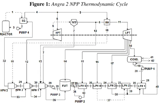
Besides all processes and equipments described above, Angra 2 has many other devices necessary for its satisfactory operation. They are: low pressure heaters (LPHs), high pressure heaters (HPHs), pumps, feedwater tank (FWT), water or moisture separator (MS) and reheater (RH). Both LPHs and HPHs preheat water, by recovering heat to increase its temperature, before it reaches steam genera-tor in order to increase system thermal efficiency. Similarly, reheater superheats steam before it drives low pressure turbine, increasing system overall performance. All these devices and their po-sition in the NPP, alongside with the thermodynamic cycle for system, can be seen in Figure 1. Figure 1 represents the thermodynamic cycle of the system from a simplified version of the thermal diagram for Angra 2 presented in FSAR [13]. The points numbered from 1 to 43 in this figure rep-resent thermodynamic states and are used in next sections to develop both energy and exergy mod-els.
Figure 1: Angra 2 NPP Thermodynamic Cycle
Source: adapted from FSAR [13].
2.2. Defining thermodynamic states and properties
Using reference data from FSAR [13] was determined the thermodynamic state in every point of the NPP defined in Figure 1. The values of pressure and temperature or quality provided by FSAR [13], to the points 1 to 43, were implemented in EES software to obtain the values of enthalpy and entro-py related to every point, using water as working fluid. Additionally, point 0 refers to water at dead state condition. So, the obtained values of thermodynamic properties are shown in Table 1 and are used latter during energy and exergy calculations. The values -100 and 100 at quality column in Table 1, are respectively designate as subcooled liquid and superheated steam, while the values be-tween 0 and 1 represent saturated condition or two phase liquid-vapor.
Additionally, Table 1 also presents the flow values of mass, energy and exergy for each point of the NPP. Such parameters are calculated in next sections, but they are already shown here in order to allow visualization in a single table of all the thermodynamic variables and properties involved in paper development.
The basic law of mass balance for each component of the nuclear power plant, considering steady state conditions, is:
min = mout (1) Equations from (2) to (24) are obtained when implementing Eq. (1) in EES software for every sin-gle component of the NPP. In addition to these equations and using Table 2 with the input values of mass flow rate from FSAR [13] is possible to determine the mass flow rate in every point of the system, as previously shown in Table 1. Additionally, mass flow rate in points 1, 2 and 3 are ob-tained later by energy analysis considering reactor and steam generator.Table 1: Thermodynamic properties based on FSAR [13] source data.
State Point, i Pressure P,[bar] Temperature T,[°C] Quality x,[-] Enthalpy h,[kJ/kg] Entropy s,[kJ/kg*K] Mass flow ,[kg/s] Energy flow ,[MW] Exergy flow ,[MW] 0 1 25 -100 104.8 0.3669 - - - 1 157 324.9 -100 1,482.33 3.472 19,643.87 29,119 8,874 2 157 291.1 -100 1,289.18 3.14 19,643.87 25,324 7,025 3 163.5 291.4 -100 1,290.38 3.14 19,643.87 25,348 7,045 4 66.41 282.3 0.998 2,773.33 5.834 2,069.35 5,739 2,149 5 66.22 282.1 0.9961 2,770.66 5.83 1,943.04 5,384 2,015 6 11.65 186.7 0.8676 2,519.75 5.96 1,781.56 4,489 1,332 7 11.46 185.9 -100 789.37 2.197 230.60 182 32.06 8 11.46 185.9 0.9971 2,776.94 6.526 1,456.71 4,045 1,217 9 59.19 274.7 0.9927 2,773.30 5.874 126.31 3,50.3 129.7 10 57.53 272.8 -100 1,198.85 3.001 126.31 151.4 39 11 11.08 237.7 100 2,909.98 6.816 1,456.71 4239 1,285 12 22.85 219.3 0.8933 2,602.49 5.887 161.49 420.3 137.6 13 11.46 185.9 0.9971 2,776.94 6.526 94.24 261.7 78.76 14 4.96 164.3 100 2,777.23 6.891 66.96 186 48.69 15 2.378 125.8 0.9727 2,654.85 6.92 83.36 221.3 49.7 16 0.891 96.44 0.8281 2,280.52 6.344 116.34 265.3 45.8 17 0.158 55.06 0.3258 1,002.53 3.121 69.92 70.09 5.354 18 0.0763 40.62 0.897 2,326.83 7.454 1,120.13 2606 122 19 0.0763 36.6 -100 153.28 0.5266 1,306.39 200.2 1.081 20 14.54 36.7 -100 154.99 0.5274 1,306.39 202.5 2.995 21 9.39 36.7 -100 154.53 0.5276 1,306.39 201.9 2.321 22 8.89 38 -100 159.92 0.5452 1,306.39 208.9 2.538 23 8.4 42.5 -100 178.69 0.6052 1,306.39 233.4 3.669 24 7.9 52.5 -100 220.45 0.7356 1,306.39 288 7.431 25 7.41 92.2 -100 386.70 1.217 1,306.39 505.2 36.95 26 6.92 124.3 -100 522.41 1.574 1,306.39 682.5 75.52 27 6.92 124.4 -100 522.83 1.575 1,389.75 726.6 80.48 28 5 151.6 -100 639.23 1.858 2,069.35 1,323 185.7 29 82.65 152.9 -100 649.60 1.863 2,069.35 1,344 204.4 30 81.67 182 -100 775.67 2.149 2,069.35 1,605 288.5 31 80.69 215.9 -100 926.51 2.469 2,069.35 1,917 403.4 32 69.66 218.9 -100 939.81 2.499 2,069.35 1,945 412.5 33 57.53 226.7 -100 975.29 2.573 126.31 123.2 26.86 34 22.85 185 -100 785.93 2.186 287.80 226.2 39.91
35 22.85 158.5 -100 670.13 1.926 612.64 410.5 61.55 36 6.92 125.8 -100 528.79 1.59 83.36 44.08 4.953 37 0.891 96.4 -100 403.88 1.266 116.34 46.99 3.603 38 0.158 55 -100 230.24 0.7679 69.92 16.1 0.4079 39 0.891 46.3 -100 193.92 0.6555 116.34 22.56 0.3522 40 0.891 42.3 -100 177.19 0.6029 186.26 33 0.3745 41 1 25 -100 104.84 0.3669 291,011 305103 0 42 1 27 -100 105.68 0.3697 291,011 307538 0.8162 43 2.378 125.7 -100 528.14 1.589 83.36 44.03 4.909
Table 2: Input values of mass flow rate based on FSAR [13] source data.
State Point, i Mass Flow ,[kg/s] 4 2,069.35 5 1,943.040 6 1,781.555 7 230.604 13 94.237 14 66.964 15 83.363 16 116.34 17 69.917
(i) Mass balance for reactor and steam generator;
3 2 1 m m m = = (2) 32 4 m m = (3)
(ii) Mass balance for low and high pressure heaters;
26 25 24 23 22 21 20 19 m m m m m m m m = = = = = = = (4) 43 15 36 m m m = = (5) 16 37 m m = (6) 17 38 m m = (7) 37 39 m m = (8) 39 38 40 m m m = + (9) 15 43 m m = (10) 32 31 30 29 28 m m m m m = = = = (11)
10 33 m m = (12) 33 12 34 m m m = + (13) 7 34 13 35 m m m m = + + (14) (iii) Mass balance for feedwater tank, moisture separator, reheater and condenser;
36 26 27 m m m = + (15) 35 27 14 28 m m m m = + + (16) 13 7 6 8 m m m m = − − (17) 11 8 m m = (18) 10 9 m m = (19) 40 18 19 m m m = + (20) 42 41 m m = (21) (iv) Mass balance for low and high pressure turbines;
5 4 9 m m m = − (22) 6 5 12 m m m = − (23) 17 16 15 14 11 18 m m m m m m = − − − − (24) 2.4. Energy model
The first law of thermodynamics for a control volume accounts energy exchange in many devices, such as turbines, pumps, compressors and heaters. If kinetic and potential energies can be neglected during steady state conditions, the first law simply becomes in Eq. (25). Such statement is the foun-dation for the energy model proposed in this section, used to evaluate the system and its compo-nents.
− = −W mouthout minhin Q (25)Besides that, the values of energy flow (E ) to each thermodynamic state, previously shown in Ta-i
ble 1, are calculated by implementing Eq. (26) in ESS software with the values of enthalpy and mass flow. i i i mh E = (26)
Then, by implementing in EES software Eq. (25) for every individual component of Angra 2 NPP are obtained the following energy variables:
(i) The total thermal power released by reactor and added to steam generator (SG);
) ( 1 3 1 Re m h h P actor = − (27) ) ( ) ( 1 2 4 4 32 1 h h m h h m QSG = − = − (28) (ii) Heat exchanged in low pressure heaters (LPHs) and high pressure heaters (HPHs);
40 40 39 39 38 38 21 22 20 1 , m (h h ) m h m h m h QLPH = − = + − (29) ) ( ) ( 23 22 37 37 39 20 2 , m h h m h h QLPH = − = − (30) ) ( ) ( 24 23 17 17 38 20 3 , m h h m h h QLPH = − = − (31) ) ( ) ( 25 24 16 16 37 20 4 , m h h m h h QLPH = − = − (32) ) ( ) ( 26 25 15 15 36 20 5 , m h h m h h QLPH = − = − (33) 25 25 34 34 7 7 13 13 29 30 30 1 , m (h h ) m h m h m h m h QHPH = − = + + − (34) 34 34 33 33 12 12 30 32 30 2 , m (h h ) m h m h m h QHPH = − = + − (35) ) ( ) ( 32 31 10 10 33 30 3 , m h h m h h QHPH = − = − (36)
(iii) Energy balance in feedwater tank (FWT), moisture separator (MS), reheater (RH) and conden-ser; 35 35 27 27 14 14 28 28h m h m h m h m EFWT = = + + (37)
13 13 8 8 7 7 6 6h mh mh m h m EMS = = + + (38) ) ( ) ( 9 10 8 11 8 9 h h m h h m QRH = − = − (39) ) ( ) ( 18 19 41 42 41 18 h h m h h m QCondenser = − = − (40)
(iv) Work consumed by each pump and the total pumping work required by the NPP;
) ( 20 19 20 1 , m h h WPump = − (41) ) ( 36 43 43 2 , m h h WPump = − (42) ) ( 29 28 29 3 , m h h WPump = − (43) ) ( 3 2 3 4 , m h h WPump = − (44) 4 , 3 , 2 , 1 ,
,Pumps Pump Pump Pump Pump
Total W W W W
W = + + +
(45)
(v) Work performed by LPT and HPT plus the net work done by NPP and its thermal efficiency;
) ( 6 6 12 12 5 5h m h m h m WHPT = − + (46) ) ( 14 14 15 15 16 16 17 17 18 18 11 11h m h m h m h m h m h m WLPT = − + + + + (47) LPT HPT Turbines Total W W W , = + (48) Pumps Total LPT HPT NPP Net W W W W , = + − , (49) actor NPP net NPP Thermal P W Re , , = (50) 2.5. Exergy model
Based on Moran et al. [14], exergy accounts “the maximum theoretical work obtainable from an overall system consisting of a system and its surroundings as the system comes into equilibrium with the environment or passes to the dead state”. So, exergy can be determined as a thermodynam-ic property. Then, the exergy flow in each point of Angra 2, already shown in Table 1, is calculated by Eq. (51).
(h h0) T0(s s0)
m x
E i = i i − − i −
(51)
Where, h0 and s0 are the thermodynamic properties enthalpy and entropy at dead state conditions
(T0 = 25 °C and P0 = 1 bar). According to the first law of thermodynamics, energy is always
served in devices or processes. It can never be destroyed. In contrast, exergy never can be con-served during a process because some part of it will be destroyed by irreversibility like friction and heat transfer through a finite temperature difference [14].
Applying an exergy balance for a control volume during steady state conditions, Eq. (52), it is pos-sible to determine the amount of exergy destroyed in every component of the NPP. This balance equation only considers the flows of exergy entering and leaving the system by both heat transfer and fluid flow.
0 1 0 + − − = −
Q Exin Exout ExDestroyed T T (52)In an alternative way of Eq. (52), when exergy by heat transfer can be neglected, the exergy de-stroyed in each individual device can be calculated based on the concepts of exergy as fuel and ex-ergy as product as presented in Eq. (53) and used by many authors like Şöhret et al. [18] and Balli [19]. Exergy as fuel represents the exergy added to the system like when a fuel burns in a combus-tion chamber and adds heat to the working fluid that represents exergy as product. In an alternative way, exergy as fuel and product simply represent the difference between exergy flow in and exergy flow out as in Eq. (53).
−= −
= Fuel oduct in out
Destroyed Ex Ex Ex Ex
x
E Pr
(53)
Then, the exergy destroyed in every device of Angra 2 is calculated by Eq. (53) with the expres-sions of exergy as fuel and product defined in Table 3, considering all the exergy flows in each component.
Component ExFuel ExProduct Reactor
1−(
To TReactor)
PReactor Ex1−Ex3Steam Generator (SG) Ex1 −Ex2 Ex4−Ex32
Moisture Separator (MS) Ex6 Ex7−Ex8−Ex13
Reheater (RH) Ex9 −Ex10 Ex11 −Ex8
Condenser Ex18 −Ex19 Ex42−Ex41
High Pressure Turbine (HPT) Ex5 −Ex12−Ex6 WHPT Low Pressure Turbine (LPT) Ex11−Ex14 −Ex15−Ex16−Ex17 −Ex18 WLPT Low Pressure Heater 1 (LPH1) Ex39 −Ex38 −Ex40 Ex22−Ex21
Low Pressure Heater 2 (LPH2) Ex37 −Ex39 Ex23−Ex22
Low Pressure Heater 3 (LPH3) Ex17 −Ex38 Ex24−Ex23
Low Pressure Heater 4 (LPH4) Ex16 −Ex37 Ex25−Ex24
Low Pressure Heater 5 (LPH5) Ex15 −Ex43 Ex26−Ex25
Feedwater Tank (FWT) Ex14 +Ex27 −Ex35 Ex28
High Pressure Heater 1 (HPH1) Ex7+Ex13+Ex34−Ex35 Ex30 −Ex29
High Pressure Heater 2 (HPH2) Ex12 +Ex33−Ex34 Ex31 −Ex30
High Pressure Heater 3 (HPH3) Ex10 −Ex33 Ex32 −Ex31
Pump 1 WPump,1 Ex20 −Ex19
Pump 2 WPump,2 Ex36 −Ex43
Pump 3 WPump,3 Ex29−Ex28
Pump 4 WPump,4 Ex3 −Ex2
In the specific case of reactor, exergy as fuel is calculated by Eq. (54) based on reactor temperature (TReactor = 800 °C), environmental temperature (T0) and also reactor thermal power ( Reactor).
actor actor actor Fuel P T T x E Re Re 0 Re , 1 − = (54)
Besides that, exergy destruction in reactor can be calculated according to Eq. (55) additionally to Eq. (53). This equation represents exergy destruction when the thermal power released by reactor core at 800 °C is transferred to the water coolant at a mean temperature ( Water) close to 308 °C.
− − − = actor Water actor actor actor Destroyed P T T P T T x E 0 Re Re Re 0 Re , 1 1 (55)
In this way, the total amount of exergy destroyed by the system and the exergy efficiency for each device can be respectively determined by Equations (56) and (57).
= Destroyed NPP Destroyed Ex x E , (56) Fuel Destroyed Fuel oduct x E x E x E x E − = = Pr 1 (57)Additionally, the total amount of exergy in or supplied by the system and the total exergy out the NPP also its exergy efficiency are calculated according to the following equations:
Pumps Total actor Fuel in Total Ex W x E , = ,Re + , (58) Turbines Total out Total W x E , = , (59) NPP Destroyed out Total in Total Ex Ex x E , = , + , (60) in Total NPP Destroyed in Total out NPP x E x E x E x E , , , 1 − = = (61)
All equations presented in this section were implemented in EES software with the values of ther-modynamic properties from Table 1. The model described above neglects chemical exergy.
3. RESULTS AND DISCUSSIONS
In this section are presented and discussed the main results of the paper, including:
I. Heat exchanged and work related to each device of Angra 2 plus system thermal efficiency. II. Exergy destroyed in all equipments of the nuclear power plant and its exergy efficiency.
3.1. Energy Analysis
The results presented in Table 4 are related to the energy model described in section 2.4 for Angra 2 NPP and its components. Remembering, the values of energy flow for each state, calculated by Eq. (26), were already shown in Table 1.
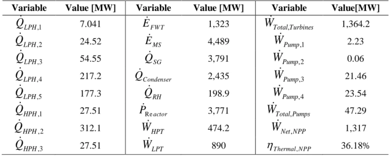
The highest values of heat exchanged considering low and high pressure heaters occur in LPH4
(217.2 MW), LPH5 (177.3 MW) and HPH2 (312.1 MW) and represent the energy added to the
system thermal efficiency. Additionally, reheater needs 198.9 MW to superheat steam, turning it from state 8 to 9, before it drives low pressure turbine to produce electricity. Besides that, conden-ser releases 2,435 MW to seawater, while the values of energy exchange in feedwater tank (1,323 MW) and in moisture separator (4,489 MW) represent the balance between the total energy flows in and out in such devices.
LPT and HPT respectively produce 474.2 MW and 890 MW, representing a total work of 1,364.2 MW. Besides that, the net work done by the NPP corresponds to 1,317 MW because the system consumes 47.29 MW in 4 pumps. Additionally, reactor releases a thermal power of 3,771 MW. These values of net work and thermal power are close to the real values of Angra 2 provided by FSAR [13], and this validates the proposed model and its results. Finally, Angra 2 has thermal effi-ciency of 36%; it is a common effieffi-ciency value for PWR plants or NPP systems like those ones available in the literature presented by Durmayaz and Yavuz [8] and Terzi et al. [12], what also validates the energy model.
Table 4: Energy values for each device and thermal efficiency of Angra 2.
Variable Value [MW] Variable Value [MW] Variable Value[MW]
1 ,
LPH
Q 7.041 EFW T 1,323 WTotal,Turbines 1,364.2
2 , LPH Q 24.52 EMS 4,489 WPump,1 2.23 3 , LPH Q 54.55 QSG 3,791 WPump,2 0.06 4 , LPH Q 217.2 QCondenser 2,435 WPump,3 21.46 5 , LPH Q 177.3 QRH 198.9 WPump,4 23.54 1 , HPH
Q 27.51 PReactor 3,771 WTotal,Pumps 47.29
2 , HPH Q 312.1 WHPT 474.2 WNet,NPP 1,317 3 , HPH Q 27.51 WLPT 890 Thermal,NPP 36.18% 3.2. Exergy Analysis
The values of exergy flow for every point of the NPP calculated by Eq. (51) were previously shown in Table 1. As can be seen in such table, the values of exergy flow are always smaller than the ener-gy one to a well-defined thermodynamic state. It happens because exerener-gy represents the amount of work that can be produced from an energy source based on dead state conditions, as represented in Eq. (51).
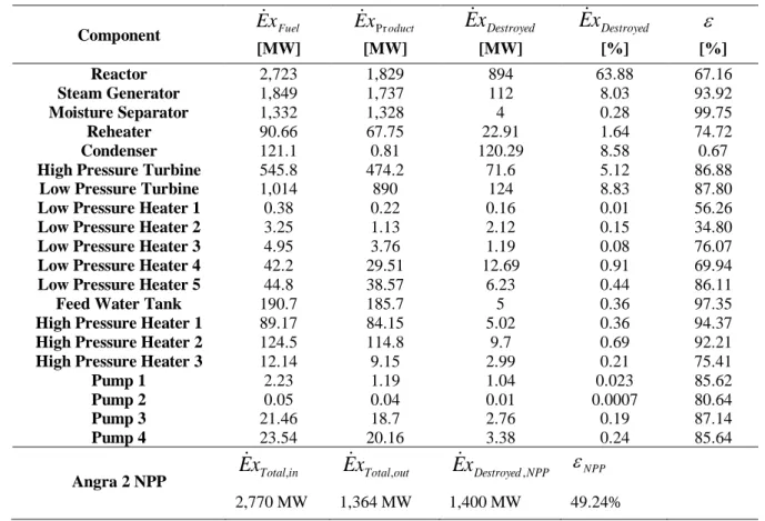
Additionally, Table 5 presents the values of exergy as fuel, exergy as product, exergy destroyed plus the exergy efficiency for Angra 2 and its components. According to the results, the main com-ponents responsible for exergy destruction (in MW or %) are the reactor (894 MW or 63.88%), low
pressure turbine (124 MW or 8.83%), condenser (120.29 MW or 8.58%), steam generator (112 MW or 8.03%), high pressure turbine (71.6 MW or 5.12%) and reheater (22.91 MW or 1.64%). These six components represent 96% (134.5 MW) of all exergy destruction in Angra 2.
Table 5: Exergy values for Angra 2 and its components.
Component ExFuel ExProduct
Destroyed x
E ExDestroyed
[MW] [MW] [MW] [%] [%] Reactor 2,723 1,829 894 63.88 67.16 Steam Generator 1,849 1,737 112 8.03 93.92 Moisture Separator 1,332 1,328 4 0.28 99.75 Reheater 90.66 67.75 22.91 1.64 74.72 Condenser 121.1 0.81 120.29 8.58 0.67
High Pressure Turbine 545.8 474.2 71.6 5.12 86.88
Low Pressure Turbine 1,014 890 124 8.83 87.80
Low Pressure Heater 1 0.38 0.22 0.16 0.01 56.26
Low Pressure Heater 2 3.25 1.13 2.12 0.15 34.80
Low Pressure Heater 3 4.95 3.76 1.19 0.08 76.07
Low Pressure Heater 4 42.2 29.51 12.69 0.91 69.94
Low Pressure Heater 5 44.8 38.57 6.23 0.44 86.11
Feed Water Tank 190.7 185.7 5 0.36 97.35
High Pressure Heater 1 89.17 84.15 5.02 0.36 94.37
High Pressure Heater 2 124.5 114.8 9.7 0.69 92.21
High Pressure Heater 3 12.14 9.15 2.99 0.21 75.41
Pump 1 2.23 1.19 1.04 0.023 85.62 Pump 2 0.05 0.04 0.01 0.0007 80.64 Pump 3 21.46 18.7 2.76 0.19 87.14 Pump 4 23.54 20.16 3.38 0.24 85.64 Angra 2 NPP ExTotal,in out Total x E , ExDestroyed,NPP NPP 2,770 MW 1,364 MW 1,400 MW 49.24%
The reactor core is the most inefficient device in the NPP, as previously discussed by Durmayaz and Yavuz [8] and Terzi et al. [12]. It has exergy efficiency of 67.16% and destroys 894 MW, the equivalent to 63.88% of all exergy destruction in Angra 2. It happens because the thermal power released by reactor core at 800 °C is added to the water coolant at around 308 °C by heat transfer. In this way, according to equations (54) and (55), how higher is the difference temperature between the reactor core and water coolant, the higher will be exergy destruction, reducing system overall performance.
Low and high pressure turbines destroy 124 MW and 71.6 MW respectively, equivalent to 8.83% and 5.12% of all exergy destroyed in Angra 2, during electricity production due to alterations in steam thermodynamic conditions, like enthalpy and entropy, as it pass through such devices. Both LPT and HPT have high exergy efficiency close to 87%. On the other hand, steam generator and reheater destroy respectively 112 MW and 22.91 MW, equivalent to 8.03% and 1.64% of all exergy
destroyed in the NPP, during heat transfer processes to produce and superheat steam. Condenser has exergy efficiency of 0.67% and destroys 120.29 MW or 8.58% of the total exergy destruction. LPHs, HPHs and pumps, represent 4% of the total exergy destroyed in the plant.
Finally, Angra 2 NPP has exergy efficiency of 49.24%, based on a total exergy in of 2770 MW supplied by reactor and pumps with a total amount of exergy destruction of 1,400 MW in its com-ponents plus an exergy out of 1,364 in the form of net work performed by HPT and LPT. There is a small difference of 6 MW among the total net flow of exergy in and out that represents the errors related to the output values of properties like entropy and enthalpy provided by EES software. Therefore, the value of exergy efficiency for Angra 2 and its components are close to some values available in the literature for nuclear power plants, like those presented by Durmayaz and Yavuz [8] and Terzi et al. [12], validating the proposed model and its results.
4. CONCLUSIONS AND FUTURE IDEAS
The aim of the paper was to evaluate Angra 2 NPP and its components based on energy and exergy analyses in order to quantify system thermodynamic performance. It was also possible to determine the most inefficient devices in the plant. According to the results, Angra 2 has energy efficiency of 36.18% and exergy efficiency of 49.24%. Reactor core is the most inefficient device in the NPP; it has exergy efficiency of 67.16% and is responsible for 63.88% of all exergy destroyed in Angra 2. So, the aim of the paper was achieved.
Additionally, in next step it will be performed an advanced exergy analysis to assess Angra 2 NPP and its components in order to better understand the entire system and identify its true potential for improvements. Advanced exergy is a relatively new methodology and complements the traditional exergy approach. It has been addressed by many authors like Şöhret et al. [18] and Balli [19] to evaluate many different thermal systems or power plants.
ACKNOWLEDGMENTS
The authors are grateful to the Coordenação de Aperfeiçoamento de Pessoal de Nível Superior (CAPES), the Fundação de Amparo à Pesquisa do Estado de Minas Gerais (FAPEMIG), and the
Conselho Nacional de Desenvolvimento Científico e Tecnológico (CNPq) for the support.
1. OZCAN, H.; DINCER, I. Thermodynamic modeling of a nuclear energy based integrated system for hydrogen production and liquefaction. Comput. Chem. Eng., v. 90, p. 234-246, 2016.
2. KOMIYAMA, R.; FUJII, Y. Long-term scenario analysis of nuclear energy and variable re-newables in Japan's power generation mix considering flexible power resources. Energy
Policy, v. 83, p. 169-184, 2015.
3. KHALID, F.; DINCER, I.; ROSEN, M. A. Comparative assessment of CANDU 6 and Sodi-um-cooled Fast Reactors for nuclear desalination. Desalination, v. 379, p. 182-192, 2016.
4. HUHTALA, A.; REMES, P. Quantifying the social costs of nuclear energy: Perceived risk of accident at nuclear power plants. Energy Policy, v. 105, p. 320-331, 2017.
5. Eletrobras Eletronuclear: Panorama da energia nuclear no mundo – edição de 2016,
Availa-ble
at:<http://www.eletronuclear.gov.br/LinkClick.aspx?fileticket=SG_9CnL80wM%3d&tabid
=406>. Last accessed: 27 Nov. 2017.
6. VERKHIVKER, G. P.; KOSOY, B. V. On the exergy analysis of power plants. Energy
Convers. Manag., v. 42, n. 18, p. 2053-2059, 2001.
7. MANESH, M. H. K.; AMIDPOUR, M. Multi-objective thermoeconomic optimization of coupling MSF desalination with PWR nuclear power plant through evolutionary algorithms.
Desalination, v. 249, n. 3, p. 1332-1344, 2009.
8. DURMAYAZ, A.; YAVUZ, H. Exergy analysis of a pressurized-water reactor nuclear-power plant. Appl. Energy, v. 69, n. 1, p. 39-57, 2001.
9. ZARE, V.; MAHMOUDI, S. M. S.; YARI, M. Ammonia–water cogeneration cycle for uti-lizing waste heat from the GT-MHR plant. Appl. Therm. Eng., v. 48, p. 176-185, 2012.
10. YARI, M; MAHMOUDI, S. M. S. Utilization of waste heat from GT-MHR for power gen-eration in organic Rankine cycles. Appl. Therm. Eng., v. 30, n. 4, p. 366-375, 2010.
11. AL-ZAREER, M.; DINCER, I.; ROSEN, M. A. Development and assessment of a novel in-tegrated nuclear plant for electricity and hydrogen production. Energy Convers. Manag., v. 134, p. 221-234, 2017.
12. TERZI, R.; TÜKENMEZ, İ.; KURT, E. Energy and exergy analyses of a VVER type nucle-ar power plant. Int J Hydrogen Energy, v. 41, n. 29, p. 12465-12476, 2016.
13. Final Safety Analysis Report (FSAR), (2013).
14. MORAN M. J.; SHAPIRO, H. N.; BOETTNER, D. D.; BAILEY, M. B. Fundamentals of
15. KLEIN, S.; NELLIS, G. Thermodynamics. New York: Cambridge. 2012.
16. BORGNAKKE, C.; SONNTAG, R. E. Fundamentals of Thermodynamics. Wiley Global Education. 2016.
17. Eletrobras Eletronuclear: Angra 2. Available at:
<http://www.eletronuclear.gov.br/aempresa/centralnuclear/angra2.aspx>. Last accessed: 27
Nov. 2017.
18. ŞÖHRET, Y. et al. Advanced exergy analysis of an aircraft gas turbine engine: Splitting ex-ergy destructions into parts. Enex-ergy, v. 90, p. 1219-1228, 2015.
19. BALLI, O. Advanced exergy analyses of an aircraft turboprop engine (TPE). Energy, v.
![Table 1: Thermodynamic properties based on FSAR [13] source data.](https://thumb-eu.123doks.com/thumbv2/123dok_br/18280420.881603/6.892.73.819.499.1163/table-thermodynamic-properties-based-fsar-source-data.webp)
![Table 2: Input values of mass flow rate based on FSAR [13] source data.](https://thumb-eu.123doks.com/thumbv2/123dok_br/18280420.881603/7.892.61.825.148.307/table-input-values-mass-flow-based-fsar-source.webp)