F
ACULDADE DEE
NGENHARIA DAU
NIVERSIDADE DOP
ORTOA remote monitoring and control
system for ecosystem replication
experiments
João Pinto dos Santos Ventura
MSCDISSERTATION Supervisor: Nuno Alexandre Cruz
Co-supervisor: Fernando Lima
Resumo
O estudo de ecossistemas naturais é uma tarefa complicada, principalmente devido aos seus cus-tos elevados e logística complexa. Assim, de forma a contornar essas dificuldades, diversos in-vestigadores têm vindo a realizar experiências num sistema fechado, de forma a replicar os ecos-sistemas em condições controladas e facilmente replicadas e repetidas. De forma a replicar os ecossistemas mencionados, tem-se assistido ao uso de aparelhos electrónicos, tais como sensores e actuadores, de forma a controlar os parâmetros ambientais, ao mesmo tempo que é feita a moni-torização do seu impacto.
Devido à globalização, que facilita a inclusão de membros de todo o mundo em equipas de investigação, existe uma crescente necessidade de controlar e monitorizar os aparelhos utilizados para a replicação das experiências de forma remota.
Actualmente, os investigadores do CIBIO têm vindo a desenvolver o seu próprio sistema para replicação de ecossistemas, que faz uso de um microcontrolador, capaz de supervisionar os sen-sores e actuadores utilizados. No entanto, este sistema é controlado localmente, o que obriga à presença física e portanto, de forma a possibilitar este requisito, é apresentado nesta dissertação o desenvolvimento de um sistema para controlo e monitorização remotos para múltiplas experiên-cias, independentes entre si. Primeiro são apresentados os principais conceitos que servem de base à arquitetura do sistema, de seguida, o design final da arquitectura e, por fim, a sua implementação. A arquitetura de sistema proposta está dividida em três camadas, sendo que a de base é com-posta pelos modulos de sensorização e atuação já existentes, que irão comunicar, através de um protocolo de comunicação sem fios, com um coordenador, pertencente à camada intermédia, que serve como elo de ligação ao Sistema de Gestão de Base de Dados e à Interface do sistema, que se situam na camada final e cujo acesso é feito através da Internet.
De forma a implementar esta arquitetura, é usado o Protocolo IEEE 802.15.4 para Comuni-cações Sem Fios, uma BeagleBone Black como coordenador do hardware associado às experiên-cias, que é composto por um Arduino Mega, do Sistema de Gestão de Base de Dados PostgreSQL e uma Interface para o Sistema, construída com recurso a PHP e HTML.
Por fim, a praticabilidade do sistema é analisada e confirmada, sendo esta feita com recurso a vários testes onde a Interface do Sistema é utilizada para controlar os aparelhos responsáveis pelas experiências. A observação dos resultados obtidos através dos testes é encorajadora, uma vez que o funcionamento do sistema como um todo é validado, no entanto, existe ainda margem para melhorias no mesmo.
Abstract
The study of natural ecosystems is a hard task, due to its costs. and logistical complexity. So, in order to deal with these difficulties, researchers have been using enclosed experiments, in order to replicate ecosystems in controlled and repeatable conditions. To replicate said ecosystems, researchers have been employing the use of electronic devices, such as sensors, and actuators, in order to control the ambient parameters in the ecosystem, while monitoring its impact.
Due to globalization, research teams often include members from all around the world, and to facilitate the data validation, the need for remote monitoring and control of the replication experiments is rising.
Currently, researchers at CIBIO have been developing their own system for ecosystem repli-cation, by having a micro controller supervising the sensors and actuators. Yet, this system cannot be controlled remotely, and so, in order to enable said behaviour this dissertation presents the de-velopment of a remote monitoring and control for multiple and independent experiments, namely, ecosystem replication experiments. First, the main concepts behind the system architecture are presented, secondly its design, and finally its implementation is presented.
The proposed system architecture is divided in three tiers, with the current Sensor and Actu-ator Nodes on the bottom tier, connected via a Wireless Communications Protocol to a Central Coordinator Node, in the middle tier, which is responsible for establishing the bridge between the Sensor and Actuator Nodes and Top Tier, which is composed by the Relational Database Manage-ment System, where the information is stored, and the System Interface, where the user interacts with the experiments.
The implementation of said architecture makes use of IEEE 802.15.4 Standard for Wireless Communications, a BeagleBone Black as a coordinator for the experiment devices, an Arduino Mega as the monitoring and control device for each experiment, a PostreSQL Relational Database Management System, and a System Interface built resorting to PHP and HTML.
Afterwards, the practicability of the system is analysed and confirmed by resorting to tests where the System Interface is used to effectively control the experiments’ devices. The observa-tion of the tests’ results is encouraging, since it demonstrates that the system works as planned, although there is still margin for improvements.
Agradecimentos
Pese embora a escrita deste documento ser feita em inglês, decidi escrever estes agradecimentos em Português.
Assim, gostaria de começar por agradecer ao meu orientador, o Professor Nuno Alexandre Cruz, pela disponibilidade que mostrou ao longo do projecto e pelo facto de me ter proporcionado a oportunidade de atacar este desafio com relativa liberdade de escolha em relação à solução a implementar. Sei que fruto disso irei terminar este percurso com garantias de vir a ser um engenheiro capaz no futuro.
De seguida, gostaria de agradecer aos investigadores do CIBIO, Fernando Lima e Rui Seabra, pelo facto de terem proposto este desafio e pelo entusiamo demonstrado.
Por outro lado, gostaria também de agradecer à minha família e aos meus amigos mais próx-imos, por todos os momentos que passamos, saibam que sem vocês isto não era a mesma coisa.
João Ventura
“Or maybe there are no good people, maybe there are only good decisions”
John Reese in Person Of Interest
Contents
1 Introduction 1 1.1 Context . . . 1 1.2 Motivation . . . 2 1.3 Objectives . . . 2 1.4 Document Structure . . . 32 State of the Art 5 2.1 Introduction . . . 5
2.2 Present System at CIBIO . . . 6
2.3 Networked Control Systems . . . 7
2.3.1 Wireless Sensor and Actuator Networks . . . 8
2.3.2 Summary . . . 10
2.4 Remote Laboratories . . . 11
2.4.1 Summary . . . 13
2.5 Embedded Devices for Remote Control . . . 13
2.5.1 Single Board Computers . . . 13
2.5.2 Network Topologies and Protocols . . . 14
2.6 Data Storage on the Internet . . . 17
2.6.1 Databases . . . 17
2.6.2 Webservers . . . 19
3 Challenge and proposed solution 21 3.1 Presenting the challenge . . . 21
3.2 System Requirements . . . 21
3.3 System Architecture . . . 23
3.3.1 Design Criteria . . . 24
3.4 Hardware and Software Selection . . . 24
4 Implementation 27 4.1 Data Packets . . . 27
4.2 Relational Database Management System . . . 28
4.2.1 Administration Tool . . . 28
4.2.2 Web server . . . 28
4.2.3 Entity Relationship Model . . . 29
4.3 Network Configuration . . . 30
4.3.1 Xbee PRO Series 1 . . . 30
4.4 Central Coordinator Node . . . 35
4.4.1 Software . . . 35 ix
4.4.2 Algorithm . . . 37
4.5 Sensor and Actuator Node . . . 41
4.5.1 Arduino Uno/Mega . . . 41 4.5.2 Xbee Library . . . 41 4.5.3 Firmware . . . 42 4.6 System Interface . . . 48 4.6.1 Website Architecture . . . 48 4.6.2 RDBMS Interaction . . . 51 4.6.3 Data Visualisation . . . 52
5 Testing and System Validation 55 5.1 Communications between the CCN and SANs . . . 55
5.1.1 ID Attribution . . . 55
5.1.2 Experiment Deployment . . . 58
5.1.3 Acknowledging Loss of Communications . . . 62
5.2 Communications between the CCN and DBMS/System Interface . . . 64
5.2.1 System State . . . 64
5.2.2 Data Storage . . . 64
5.2.3 Data Visualization . . . 65
6 Conclusions and Future Work 67 6.1 Future Work . . . 68
A User Manual 69 A.1 Setting Up the Hardware . . . 69
A.1.1 SANs . . . 69
A.1.2 CCN . . . 70
A.2 System Interface . . . 70 B Abstract Submitted to OCEANS’16 MTS/IEEE Monterey Conference 75
List of Figures
2.1 Current Hardware . . . 6
2.2 Present system architecture . . . 6
2.3 Original Setup String . . . 7
2.4 NCS Shared Network Architecture . . . 8
2.5 NCS Hierarchical Structure Architecture . . . 8
2.6 WSAN Basic Architecture . . . 9
2.7 Sensor Node . . . 10 2.8 Sensor/Actuator Node . . . 10 2.9 Characterization of Experiments . . . 11 2.10 WebLab 3-level . . . 12 2.11 Star Topology . . . 14 2.12 Mesh Topology . . . 15 2.13 Ring Topology . . . 15
2.14 Components Of A Database System . . . 17
2.15 Components Of A Database System With SQL . . . 17
2.16 Functionalities of a DBMS . . . 18
2.17 DBMS Three-Tier Architecture . . . 18
3.1 System Architecture . . . 23
4.1 Setup Data Packet . . . 27
4.2 Log Data Packet . . . 27
4.3 Entity Relationship model . . . 29
4.4 Xbee API Mode Data Structure . . . 31
4.5 Xbee API Mode 2 Data Structure . . . 32
4.6 Xbee 64-bit Tx Request . . . 32
4.7 Xbee 64-bit Rx Request . . . 33
4.8 X-CTU Interface . . . 33
4.9 802.15.4 Channel number And PAN Identifier . . . 34
4.10 Setting the Xbee Baud Rate . . . 34
4.11 Xbee Mode of Operation Selection . . . 34
4.12 Xbee IEEE Module Address . . . 35
4.13 Disabling Xbee 16-bit address . . . 35
4.14 Cloud 9 Interface . . . 36
4.15 Client Sequence . . . 38
4.16 Flowchart of Xbee Communication Establishment . . . 38
4.17 Flowchart of Message Reception Processing . . . 39
4.18 Flowchart of database queries . . . 40 xi
4.19 Flowchart of SAN State Machine . . . 43
4.20 Flowchart of SAN ID Request . . . 44
4.21 Flowchart of SAN Setup Request . . . 45
4.22 Flowchart of SAN Message Sending . . . 46
4.23 Flowchart of SAN Message Receive . . . 47
4.24 Web-Page Use Case Diagram . . . 48
4.25 Experiments and Supervise Use Case Diagram . . . 49
4.26 View Stored Data Use Case Diagram . . . 49
4.27 Web-site Architecture . . . 50
5.1 Sending And Confirmation Of "Request ID" By The SAN . . . 56
5.2 CCN Receiving "Request ID" Message . . . 56
5.3 CCN Attributing ID . . . 57
5.4 SAN Confirming The Reception Of ID Value . . . 57
5.5 CCN Receives "Got ID" Message . . . 58
5.6 SAN Number Two Requesting And Acknowledging the Reception Of A Setup Length . . . 60
5.7 Reception of "Request Setup" Message By The CCN . . . 60
5.8 SAN Number 2 Receiving Setup And Acknowledge Message . . . 61
5.9 SAN Number 2 Stored Setup . . . 61
5.10 SAN Number 2 Sending A Log Message . . . 62
5.11 CCN Receiving a Log Message From SAN Number 2 . . . 62
5.12 SAN Number 1 Failing to Deliver A Log Message . . . 62
5.13 System Interface Displaying Lost Communications From SAN Number 1 . . . . 62
5.14 System Interface Displaying Lost Communications From All SANs . . . 63
5.15 Communications Between CCN And SAN Number 1 Restored . . . 63
5.16 Communications Between CCN And SAN Number 2 Restored . . . 63
5.17 Available Setups . . . 64
5.18 SAN Running Experiments . . . 64
5.19 Stored Log Data . . . 64
5.20 Displaying Last Message Received . . . 65
5.21 Plot of SAN ID 1 Running Setup ID 1 on the System Interface . . . 65
5.22 Plot of SAN ID 1 Running Setup ID 1 with Data Downloaded From Data Tables . 65 A.1 Xbee Switch Position . . . 69
A.2 Login . . . 70
A.3 Register . . . 70
A.4 Main Page . . . 71
A.5 Website Menu . . . 71
A.6 Setup Selector . . . 71
A.7 Setup Questionary . . . 72
A.8 Tables Presenting Setups Stored . . . 72
A.9 Tables Presenting Logged Data . . . 73
List of Tables
2.1 Comparison between BeagleBone Black and Raspberry Pi 2 . . . 14
2.2 Wireless Communication Protocol Comparison . . . 16
4.1 Setup Example . . . 41
5.1 Setup ID Number 1 . . . 59
5.2 Setup ID Number 2 . . . 59
Abbreviations
BBB BeagleBone Black CCN Central Coordinator Node DBMS Database Management System FFD Full-function device
GPIO General Purpose Input/Output HTML HyperText Markup Language
IDE Integrated Development Environment JSON JavaScript Object Notation
LAN Local Area Network LED Light Emitting Diode MAC Medium Access Control NCS Networked Control System PAN Personal Area Network PHP Hypertext Pre-processor PHY Physical layer
RDBMS Relational Database Management System RFD Reduced-function device
RTC Real-Time Clock
SAN Sensor and Actuator Node SQL Structured Query Language WLAN Wireless Local Area Network WPAN Wireless Personal Area Network WSAN Wireless Sensor and Actuator Network WSN Wireless Sensor Network
Chapter 1
Introduction
In this chapter the context and motivation behind this dissertation are presented, as well as the objectives proposed and the document’s structure.
1.1 Context
Natural Ecosystems are biological environments that can be found in nature and ranging from aquatic to terrestrial. In the case of this dissertation, the main focus of study are aquatic ecosystems such as marine ecosystems, with high salinity and fresh water ecosystems, with low salinity levels. However, there are other aquatic ecosystems, which cannot be labeled in such as strict way. The study of the aquatic ecosystems is significant in order to determine, among others, the effects of climate change on species’ distribution [1].
Aforesaid studies can be done in the ecosystem itself or through a replication of it in a labo-ratory. However, the study of natural ecosystems, such as the aquatic one, has been proven to be a difficult task, mainly because of the logistical issues it imposes, which are often impossible to deal with and its high cost as referred on [2].
In order to deal with these difficulties, enclosed experiments have been used, as they enable the replication of ecosystems in controlled and repeatable conditions. These replication experiments can be done in various scales concerning space, varying from a small scale, often done in small containers, medium scale, which requires the use of mesocosms, or a large-scale experiment, in which the whole ecosystem is simulated [3].
In long-term experiments, the time-span can vary from weeks to years [1], and so there is a bigger necessity for a remote monitoring and control system, since the impact of a single event, such as deviation on water temperature, can render the experiment unsuccessful. Considering that this task relies on electronic equipment, the effects of water on it cannot be neglected, as it might be the reason for malfunction or permanent damage.
In addition, said system will maximize the possibilities for an investigator to tackle other issues, without having to actively take care of ongoing experiments. Also, multidisciplinary teams, whose members might be from all around the globe, often do the conduction of such experiments.
This adds a problem, since some members will not be able to access the experiment, making them dependent on other members to view the data and control the equipment. Furthermore, the necessity for validation from peers further highlights the importance of remote access to the data acquired from such experiments, for quicker evaluation and validation of the results.
1.2 Motivation
This experiment supervising and control system is to be implemented in a Portuguese research center, CIBIO, which main purpose is centered on biodiversity and genetic resources. For further study of aquatic ecosystems, a system capable of reproducing such ecosystems is already in place. Taking into consideration the wide variety of aquatic ecosystems, there is the need for a flexible data acquisition and control system, capable of adapting to different requirements needed for each specific experiment.
Currently, the monitoring and control hardware in place is a prototype built with low-cost components, whose development has evolved through various iterations. The data logger devel-opment is reported on a paper published in a scientific journal [1], allowing anyone to freely reproduce it. However, there is a main issue, which is the inability for someone to access the data acquired remotely. The solving of this issue is critical, since deviations in various variables, such as temperature, or a power loss of the system itself, which result in the failure to replicate a specific ecosystem scenario, will render the experiment a failure, or at best, a partial success. If data was to be made available remotely, with an alarm system in place immediately informing the researchers, it would enable the possibility of saving the ongoing experiment. In the current situation, a failure of any kind will, most probably, be detected too late for any corrective measures to be taken.
Considering these issues, covering all the steps associated with systems engineering will help in achieving a system that is both accurate and reliable, meeting all the required specifications, which is the main motivation behind this disseratation.
1.3 Objectives
The main objective established for this dissertation is the implementation of hardware, such as a gateway, to connect the experiments to the Internet, enabling their remote monitoring and control. For this, wireless protocols between the gateway and the experiments are needed, since they allow physical separation. This leads to the development of a web application, with the goal of enabling data analysis and control of the ongoing experiments, remotely.
For this web application different authentication levels need to be implemented, with different access to data. The authentication level with highest clearance will enable the user to view data from the different experiments, upload new experiment settings and control the actuators. The lowest clearance authentication level must only enable the user to view the data imported from the experiments.
1.4 Document Structure 3
Furthermore, the web application must have alarms that take into consideration the data ac-quired in real time, in order to send notifications to the users, if the predefined thresholds are met.
Finally, after the completion of the dissertation, a paper will be written, aiming at being se-lected for OCEANS’16 MTS/IEEE Monterey Conference.
1.4 Document Structure
This document is divided in seven chapters, with the remainder of Chapter1covering the docu-ment structure.
Then, Chapter2presents the State of The Art on the topics related to this dissertation, mainly, Wireless Sensor Networs, Wireless Sensor and Actuator Networks, Networked Controlled Sys-tems, Network Topologies, Wireless Communication Protocols, Single board Computers, Database Management Systems, and web servers.
In Chapter3, the challenge and the proposed solution are presented, with detailed explanations on the architecture developed and the software and hardware chosen to play the roles described in the architecture.
In addition, in Chapter4there is a detalied description on how the system was implemented, mainly the firmware developed for Sensor and Actuator Nodes, the software for the Central Coor-dinator Node, and the System Interface. Besides this, the implementation of the chosen Wireless Communication Protocol is described, along with the relationship between all the nodes and the Database Management System.
Proceeding to Chapter 5, it contains the testing protocol followed for the validation of the system’s requirements, as well as its results.
ChapterAconsists on a manual detailing the various steps that a user shall take, in order to achieve a correctly use of the system. Finally, Chapter6addresses the conclusions obtained from the development of the system, followed by a description of future work.
Chapter 2
State of the Art
This chapter starts by presenting an introduction on monitoring and control systems, and how these can be achieved. Then, it presents the current system at CIBIO, with the following topics focusing on the literature for possible approaches in pursuance of a remote monitoring and controlling system.
2.1 Introduction
Monitoring of environments, in the last several years, has made use of networks for distributed sensing, to fully measure the parameters of interest. These networks have evolved along the years, and wireless sensor networks have been subject of broad study as they create new possibilities for sensing, by covering larger areas, and refrain from cables. With the advance of technology, which has brought down both costs and power consumptions, wireless sensor networks have become more appealing.
The necessity for controlling environmental conditions has made the inclusion of actuators on said network a logical step, thus leading to the creation of Wireless Sensor and Actuator Networks (WSAN), having the Network Control Systems (NCS) as a base for its architecture, as it enables the control and alteration of the environment by use of, for example, heating or light sources. With the incorporation of actuators, however, the complexity of the communications in the network is increased, as the protocols will have to manage many-to-one communications with sensors when these are forwarding data, and one-to-many communications when the data needs to be sent to the actuators [4]. In order to draw the complete picture on WSANs and how its components are placed on the network, further study will be made on its architecture and how can they be connected to external networks, such as the world wide web.
The link to an external network with the capacity to monitor and control the ongoing exper-iments is directly related to the concept of Remote Laboratories, which aims at providing all the features that a laboratory has physically, but over the Internet, such as total control of the experi-ments and all its instruexperi-ments
2.2 Present System at CIBIO
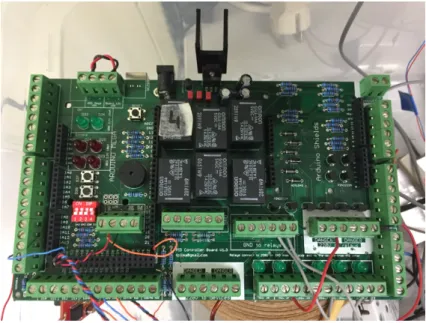
The system currently in place at CIBIO recreates marine ecosystems, with the intention of studying the behaviour of species under certain conditions. In order to do so, it employs a micro controller, which reads and stores values obtained from multiple sensors, such as temperature, water level and luminosity, and sends output orders to the actuators, based on a schedule that is pre-programmed, such as enabling a water pump, in order to simulate tides. Water temperature is controlled using infrared lamps and cooling fans, with both devices acting according to the desired value on the schedule. The system can be repeated, in order to conduce independent experiments simultane-ously. A simple system architecture is detailed in Figure2.2, and the current hardware is shown in Figure2.1.
Figure 2.1: Current Hardware
2.3 Networked Control Systems 7
Presently, there is the possibility of having underway nine experiments concurrently, however, there is no communication between them, nor to a central coordinator or supervisor. Consequently, as the experiments are independent and isolated events, with no connection to an outside network, there is no possibility of monitoring and controlling the experiments remotely at the present time. Each experiment consists of a setup, stored on an SD Card, connected to the Arduino Mega Micro controller via a Arduino SD Shield. Said setup is constituted by a previously defined number of strings, with the same data structure, as presented on Figure2.3, on which the user specifies the date when the actions shall take place, represented in seconds since 1970, and the remainder of the string consisting of bytes concerning the actuators’ operation such as:
• Temperature, in Celsius, concerning the Set Point;
• Tide, regarding the actuation of the Water Pump used to vary the water level, with its value varying between zero and one;
• Light, which controls the infrared lights responsible for heating, also varying between zero and one, like the Tide value;
Figure 2.3: Original Setup String
The firmware in place will then load the setup from the SD card, store it on an auxiliary array. Afterwards, the array is iterated, with each of its positions containing the setup strings, by comparing the actual time, provided by a Real Time Clock (RTC), with the stored time on each string. Once the actual time is equal or superior to the time indicated on the setup string, an event is triggered, taking into consideration the Temperature, Tide, and Light Bytes.
2.3 Networked Control Systems
Networked Control Systems (NCSs) are defined by [5] as "spatially distributed systems in which the communication between sensors, actuators and controllers occurs through a shared band-limited digital communication network".
Two control systems that use network communications are defined on [6], with them being shared-controlled systems and remote control systems. On shared network connections, the sensor and actuator groups communicate with their associated controller, sharing the same network, as it can be seen on Figure2.4.
Figure 2.4: A NCS Shared Network Architecture As Presented in [6]
Remote Control Systems offers a different solution, since is has subsystems of sensor and actuators along with their controller, which then communicates with a central controller, through a network. Such architecture is depicted of Figure2.5.
Figure 2.5: A NCS Hierarchical Structure Architecture As Presented In [6] 2.3.1 Wireless Sensor and Actuator Networks
For better understanding of Wireless Sensor and Actuators Network (WSAN), first there is the need to fully grasp the architecture and behaviour of Networked Control Systems, which were previously described, and Wireless Sensor Networks (WSN), both laying WSANs foundations.
A Wireless Sensor Network (WSN) consists on a network of sensor nodes with the purpose of monitoring a certain environment, which can either be a small, specific area, or a large area. It then forwards the data acquired to a sink (also referred as controller), using wireless communications, which can use the information or relay it to other networks, such as the Internet, through a gateway, thus enabling the interaction between user and the WSN to be made remotely. [4]
The main difference between WSN and WSAN lies on the presence of actuator nodes, which have the ability to alter the environment, either by a scheduled event or in response to an in-put change ([7],[4]), essentially becoming a closed-loop feedback system. In contrast to WSNs, WSANs typically require more power to operate, since it employs actuators such as water pumps or motors. Both WSNs and WSANs
2.3 Networked Control Systems 9
2.3.1.1 WSAN Architecture
WSANs are a relatively new field of study, and as such there are still few architecture examples, however, the authors of [4] offer a possible architecture, which is presented in Figure2.6
Figure 2.6: WSAN Basic Architecture As Presented In [4]
On this type of WSAN, its basic elements are nodes (sensor and actuators) connected to a local controller, that is then connected to a gateway.
Sinks are connected to the gateway, thus providing a way for connecting the WSAN to an outside network, such as the Internet. It is one of the points to be explored in this document, as it is essential for the remote monitoring and control of an experiment.
For this purpose, there is a wide range of equipment that can be used. The main focus will be on single board computer solutions, which are reliable and have the needed computing specifications in order to deal with the tasks at hand, such as establishing communications with all the sinks and relaying data between them and the user.
After further analysis on WSAN architecture, it is possible to conclude that sensor nodes, which design is presented in Figure 2.7, have the simplest hardware, since they do not need to have all the hardware necessary for actuating and controlling mechanical tools such as motors.
Figure 2.7: A Sensor Node As Presented In [4]
On WSANs there is also the possibility of employing integrated sensor/actuator nodes, as exemplified in Figure2.8which include the sensor and actuator units, a microprocessor, a battery and a means for wireless communication [8].
Figure 2.8: A Sensor/Actuator Node From A Case Study Presented In [4]
2.3.2 Summary
Wireless Sensor Networks and Wireless Sensor and Actuator Networks are useful tools for mon-itoring, or monitoring and controlling areas of various scale, from a production process, in a relatively small area, to a country’s coast, or a specific area of it, as their topology permits the presence of wireless sensor nodes which can communicate with each other and correlate the data. Nevertheless, it is not an optimal solution for the required system, as even though there is the need for sensor and actuator nodes, there is no need for communication between them, as they will be assigned to independent experiments, and their spread over an area is small.
2.4 Remote Laboratories 11
Even so, there are valuable lessons to be taken from the study of WSN and WSAN, since there is the need for a gateway in order to establish a connection to an outside network (ie Internet), which will enable to remote control the sensor/actuator nodes currently in place.
Additionally, the study of NCS also proved to be fruitful, as its possible architectures can be replicated in order to achieve a system such as the required one, since it establishes the possibility of the use of a central coordinator controller, connected to independent subsystems, as desired.
2.4 Remote Laboratories
In [9], remote laboratories are defined as online environments for operating instruments and col-lecting measurement data over the Internet. They are mostly used at universities for educational purposes [10], as they provide unlimited access to the experiment at all times, granting students with the possibility of autonomous work and learning, whilst preventing damages to the equipment and reducing the strain on laboratory occupation time.
In addition, [11] presents the characterization of remote experiments and how users can in-teract with them. In this work, experiments are classified according to the type of inin-teraction the user can have with it, the nature of the experiment itself, and the location of both the user and the experiment. There are two types of interactions possible between the user and experiments, either by having direct control over the experiment and its equipment, or the user might control the equipment via virtual instrumentation or a virtual-reality environment.
Figure 2.9: Characterization of Experiments as presented in [11]
Further along, three types of distance experiments are defined, them being based on Virtual Laboratories, Remote Laboratories with access to physical test beds and Hybrid Laboratories, which are a mix of the previous two. Although Virtual Laboratories might be of future interest, if a model of an experience is to be implemented, instead of its direct control, for this disserta-tion, the main point of interest lies on Remote Laboratories, and [11] sheds a light on its typical components, with them being:
• The experiment itself;
• The laboratory server that assures the control of said devices;
• A server links users with the Laboratory Server and Client Workstations, which assures the connection between users and the experiment alongside its resources.
Moreover, [12] sheds further light on client applications, classifying them on two groups. They can either be desktop clients running on the user’s computer or web browser clients. Desktop clients have clear advantages as they provide more flexibility comparing to web browsers, however, they are more intrusive, as they have access to all the files in a computer, and its requirements are harder to meet as they might only run on specific operating systems, contrary to a web browser client, which are supposed work on every operative system with a web browser.
As web server clients have the advantage of running on almost every platform as they are not constrained by operating systems, its concept and architecture will be further explored. On [13], the authors provide insight on user classification and their interaction with the system. Concerning with the definition of user roles, three categories are defined, the web server administrator, which administrates the Web Server, the lab administrator, who is responsible for the management of lab servers as well as the experiment devices and the user, who conducts the experiment. With this information in mind, a three-level architecture is provided, such as seen on Figure2.10.
Figure 2.10: WebLab 3-level architecture as presented in[13]
Concerning this architecture, users can create and manage their account while also being able to conduct or register new experiments. The WebLab Server works both as an Experiment Man-ager, assuming the responsibility of authenticating user and input collection, constraint verifica-tion, scheduling and results collecverifica-tion, and as a Resource Manager, then acting as a creator and maintainer of lab registers, access registers and experiment registers. The lab server has tasks of experiment manager and device manager, communicating with the experiment device controller, which is the responsible for regulating the instruments used in the experiment, sending and receiv-ing data and control signals.
2.5 Embedded Devices for Remote Control 13
2.4.1 Summary
The literature on Remote Laboratories essentially discusses the relationship between the user, the server and the experiments, with bigger focus on the first two. In essence, a Remote Laboratory is a concept similar to NCS, as both define a system that control instruments at a distance, being the Remote Laboratory specific to an application, whilst a NCS, as a concept, has broader approaches.
2.5 Embedded Devices for Remote Control
2.5.1 Single Board ComputersAll the previously stated systems require hardware in order to connect the system to an outside network. Namely, in case of the NCS, the Controller, in WSANs, a gateway, or in Remote Labo-ratories, hardware that runs the Lab Server. In order to find the best cost/performance solution, a market analysis on open-source, single board computers was made. There are various solutions on the market, such as the Arduino Uno and Mega, Intel Galileo and Edison, Banana Pi, Raspberry Pi and Raspberry Pi 2, and the BeagleBone Black, all of which serving the purpose of a prototyping tool, and costing no more than 70e. However, the latter two will be further developed, as they are the most common solutions for embedded systems of higher complexity.
BeagleBone Black
It is a fully open source single board computer, made by BeagleBone.org Foundation that runs a Unix-based Operating System, with the same functionalities as a personal computer at a much-reduced cost. In addition to its technical features, it is also expandable, due to the existence of "capes", which are dedicated boards designed by the community, which have a wide range of applications, from prototyping to wireless communications.
Raspberry Pi 2
The Raspberry Pi 2 is a single board computer, built by the Raspberry Foundation, that like the BeagleBone Black, has the same functionalities as a personal computer, at a reduced cost. It is essentially used as a tool for education on computer based subjects and for graphical applications, but it is also used in the engineering field, either as a prototyping tool, or end-use instrument.
A comparison between the characteristics of the BeagleBone Black and Raspberry Pi 2 is show on Table2.1.
Table 2.1: Comparison between BeagleBone Black and Raspberry Pi 2 Single Board Computers
Characteristics BeagleBone Black Raspbery Pi 2
CPU Cores 2 4
CPU Clock Frequency 1 GHz 900 MHz
Memory 512 MB 1 GB
Storage 4 GB eMMC, Expandable Micro SD Card Required
GPIO (General Purpose Input/Output) 65 40
Communication Protocols I2C, SPI, UART I2C, SPI, UART
USB Ports 1 4
Current Price (1st Quarter 2016) 70.05e 44.22e
2.5.2 Network Topologies and Protocols
The connection between a Gateway, Central Server, or Controller, and the experiments can be established through the use of wireless protocols, which enable to physically separate the devices, for which there are numerous topologies, such as star-shaped, mesh, ring or bus according to the possibilities of the chosen protocol, all of which will be briefly introduced.
In a star shaped topology, there is a central node that communicates independently with various nodes, rendering it impossible the direct connection between nodes. Consequently, if an end-node fails to establish communication with the central node, there is no alternative way for the flow of information to reach the central node [14].
Figure 2.11: Star Topology As Presented In [14]
Moreover, in this topology, each node can listen to all the transmissions sent by the central node directly to it, akin to a bus topology in a cabled network. However, as the mean of commu-nication between the end-nodes and the central node is wireless, the distance between them must be taken into account, since its increase might undermine the possibility of end-nodes to listen to all the information sent by the central node.
2.5 Embedded Devices for Remote Control 15
On a mesh topology, in contrast to a star topology, its end-nodes are interconnected, providing alternative routes for the flow of information, which is useful if direct connection to the central node cannot be established [14]. Nonetheless, in comparison to Star or Ring Topology, it is more complex to manage.
Figure 2.12: Mesh Topology As Presented In [14]
On ring topology, the main node and the end-nodes are sequentially connected in a ring, mak-ing the flow of information circular. As a result, information sent by a node will have to go through all of nodes between it and the destination. This may prove to be a major disadvantage, as the failure to communicate wit one node will cripple the network in such a way that the flow of information will be halted [14]
Figure 2.13: Ring Topology As Presented In [14]
These network topologies, can be implemented making use of various wireless communication protocols. As of today, the most common protocols for it are Wi-Fi (IEEE 802.14), ZigBee (IEEE 802.15.4) and Bluetooth (IEEE 802.15.1).
Wi-Fi
The Wi-Fi protocol, short for Wireless Fidelity, is defined by IEEE 802.14 standard for WLANs, allowing access to the Internet when connected to an Access Point, or in ad-hoc mode[15]. The
main purpose of this protocol is to replace or extend wired networks responsible for computer-to-computer communications.
ZigBee
ZigBee Alliance Company created ZigBee standard in 2002. Its protocol stack is built upon IEEE 802.15.4 that specifies the PHY and MAC layers. It is a self-configuring, self-healing system of redundant and low-power nodes [16], highly interesting for the automation industry and, most specifically for WSNs, in consequence of its low cost and low power consumptions [17], which is a critical requirement in this type of networks.
The implementation of devices in this protocol are divided in two types concerning their func-tionality: Full-function device, which has 3 operation modes: Personal Area Network (PAN) co-ordinator, coordinator and device, and Reduced-function device, that can only communicate with full-function devices.
Bluetooth
Bluetooth, or IEEE 802.15.1, is a standard designed for short-range devices, based on wireless radio system applied on wireless personal area network and its topology provides two connectivity options, piconet and scatternet [15]. On a piconet, one Bluetooth device acts as the master, while one up to seven devices connected act as slaves. The communication between the master and the slaves might be point-to-point or point-to-multipoint, with the slaves synchronized by the master’s clock. Scatternets consists on the connection of piconets in order to form a wider network, with the particularity that a master in a piconet can be a slave in several other piconets. One particular advantage of Bluetooth is the ability to place a device in standby mode in pursuance of power consumption reduction.
The comparison between the characteristics of the 3 Wireless Communication’s Protocols is shown on Table2.2
Table 2.2: Protocol Comparison with values adapted from [15] and [18] Protocols
Characteristics ZigBee Wi-Fi (a/b/g/n) Bluetooth
Range 10-100 m 250 m 10 m
Max number of nodes >65000 2007 8
Frequency Band 2.4 GHz (Global); 868 MHz (Europe) 2.4 GHz; 5 GHz 2.4 GHz
Max Signal Rate 250 Kb/s 600 Mb/s 1 Mb/s
Summary
After comparing the three protocols, Bluetooth might be of lesser interest if the number of nodes is high (equal or more than 8). The ZigBee protocol has the maximum number across the three protocols, and it requires lower power with its signal rate being more than enough for the application in cause. Moreover, in [15] it is also stated that ZigBee offers less complexity as it presents the lower sum of both PHY and MAC primitives.
2.6 Data Storage on the Internet 17
2.6 Data Storage on the Internet
The aim to store data, in a structured way, and make it accessible via the Internet, leads us to database management systems. A computerized database may be created and maintained either by a group of application programs written specifically for that task or by a database management system.
2.6.1 Databases
On Traditional database applications, the information stored is mostly textual or numeric, however, there are new types of database systems, often referred to as big data storage systems, or NoSQL systems, which have been created to manage data for social media applications [19].
According to [20], a database system typically consists of four components: users, the database application, the database management system (DBMS), and the database, as shown on Figure2.14.
Figure 2.14: Components Of A Database System As Presented In [20]
Due to the significance of Structured Query Language (SQL), and the fact that it is understood by all DBMS products while also being usually used by database applications to send statements to the DBMS, [20] presents an alternative architecture for the database system, as shown in Figure 2.15.
Figure 2.15: Components Of A Database System With SQL As Presented In [20]
[19] defines the Database Management System as a "computerized system that enables users to create and maintain a database, while facilitating the processes of defining, constructing, ma-nipulating, and sharing databases among various users and applications".
The Database Application role is to serve as an intermediary between the user and the DBMS, and they can read or modify data present on the database by sending SQL statements to the DBMS.
Additionally, they might also present data in the format of forms and reports. Although application programs can be acquired from software vendors, system specific solutions might be developed and employed.
Figure 2.16: Functionalities Of A DBMS As Presented In [20]
The evolution of DBMS led to the arrival of Relational Database Management Systems (RDBMS), which main difference to DBMS, is that besides storing information in tables, they also allow to store the relationships between them [21]. As of today, the most popular, open-source, Relational Database Management Systems are MySQL and PostgreSQL.
To build the database applications, there are several tools available, such as Hypertext Markup Language (HTML) and Hypertext Pre-processor (PHP). While HTML is useful for generating static Web pages, with fixed objects and text, when it comes to interactive features, PHP is a better solution, as is particularly suited for manipulation of text pages, and in particular for manipulating dynamic HTML pages at the Web server computer, as referred in [22].
Taking this into consideration, a three-tier architecture is reached, as shown of Figure2.17
2.6 Data Storage on the Internet 19
2.6.2 Webservers
The term Web Server refers to hardware, software or a combination of both. When mentioning the hardware part, a web server is a computer, or another physical device, connected to the Internet, which hosts the files associated with a web site, and handles the requests made to web pages by users. Looking at Web Servers from the software perspective, a web server controls the way users access the files hosted on the hardware, in order to execute the requests made by users [23]. There are numerous software web servers, and some of the most popular are the:
• Apache HTTP Server, which is open source and runs on the likes of Linux, Mac OS X, and Windows;
• Microsoft IIS (Internet Information Services) which is runs Windows operating systems; • Sun Java System Web server, from Oracl, which runs, among others, on Linux and Windows
operating systems;
Even though there is no real way to confirm this, the Apache HTTP Server seems to be the most popular web server software, and that being the case, to host a database, developers often use a combination of Apache-MySQL-PHP. This combination, when running on the Linux operating system, is referred to as LAMP; when running on the Windows operating system, it is referred to as WAMP [22].
Chapter 3
Challenge and proposed solution
3.1 Presenting the challenge
This dissertation aims at achieving remote monitoring and control of several experiments. As de-scribed in subchapter2.2, the system in place only allows for presential control of the experiments, and each time a user wants to start a new experiment, he has to physically access the experiments site, remove the SD Card from the SAN, and then store the new setup. Ideally, the desired final system shall be able to access each SAN, communicate with it, either by sending it orders, or logging data, and then relay it to an user on the website. In order to achieve this goal, there are system requirements to be met, which will be further explained.
3.2 System Requirements
To achieve a functional system there are several requirements to be met, some are general, related to the whole system, and some are specific to each individual block.
General Requirements:
• The system needs to handle, at least, 9 experiments at the same time.
• The experiments are all placed in the same physical space, with a few meters between them. • The experiments maximum duration is 12 months;
• The connection between the SANs and the CCN must be wireless. • Data has to be stored on a database;
• There should be a backup energy source for the central controller, to keep it operational in case of a power supply failure.
• A Web Site is required as the System’s Interface, and must be accessible via internet; • Notifications on unexpected system behaviour must be sent directly to the user;
In order to implement the General Requirements presented, the following guidelines were taken into consideration.
Website Guidelines: On the website, the user, after logging in, shall have the ability of per-forming the following actions:
• Insert new experiment setups;
• Check data from all the experiments, in real time, being able to download it; • View real time or completed plots from chosen experiments;
• Check the state of each experiments, with warnings for lost communications, and re-established communications;
• View which setups are available, and which SAN are without setups and available to start a new experiment;
• Check the last received message from any of the SAN; • Start a new experiments;
3.3 System Architecture 23
3.3 System Architecture
Figure 3.1: System Architecture
The main objective of this System Architecture is to integrate the present Sensor and Actuator Nodes (SANs) in a network, enabling the users to control and monitor the experiments remotely.
Within the architecture, each of the tiers have distinct purposes. Begining from the bottom tier - 1 - the SAN, on which the architecture was built upon, are responsible for controlling each experiment, by running a pre-defined setup, monitorize the experiments, and send periodic logging messages.
The middle-tier - 2 - consisting of the CCN is responsible for establishing the connection between several SANs and the database, meaning that it has to be capable of receiving messages from the SANs, process them, and act upon it, either by replying to it, or storing the information on the database.
The upper-tier - 3 - is divided in two sub-tiers. First, we have the DBMS, which has various roles in this system, such as storing the logging data from the active experiments, storing the setup data, and information about the active SAN on the network, and their current state. Then we have the System Interface, which gives the user the ability to monitor the experiments, via graphics and tables, and supervise the SAN state, with notifications of registered system malfunctions. Additionally, it must store the information regarding users, such as their username, password and email.
3.3.1 Design Criteria
The design of the architecture relayed heavily on the study made on WSN, WSAN and NCS presented in Chapter 2, as each of these architectures present us with a distributed architecture where we have sensor, or sensor and actuator nodes relaying information to a gateway. From the gateway on, the design was inspired by Remote Labs and Database Management Systems.
It shall be able to establish communications with each SAN individually, giving orders, receiv-ing data, and relay it to a database. Given that the maximum number of nodes is limited, the option for the network architecture fell upon a Star-based design, with the CCN being the network coordi-nator, and each SAN connected directly to it. As previously stated, one of the system requirements was for this network to be wireless. All the data is to be primarily stored on a database.
3.4 Hardware and Software Selection
Taking into account the system requirements, and the architecture developed to deal with them, the next step was to select the tools used to implement the system.
Taking into consideration the study presented on Table2.2, the IEEE 802.15.4 protocol for Wireless Communications was chosen, mainly because of the superior number of nodes that can be connected simultaneously, which is higher than the maximum number for either Bluetooth and Wi-Fi. Even though the Wi-Fi has superior range, that is not a critical requirement, as the experiments are separeted by a few meters.
With the network protocol chosen in mind, and given the extensive support by the community, reasonable price, and technical specifications, such as being able to establish a Star-Shaped Net-work, the choice for the wireless module fell upon the Xbee PRO Series 1, which has the following characteristics:
• Retries and Acknowledgements;
• Direct Sequence Spread Spectrum (DSSS); • Source/Destination Addressing;
• Unicast And Broadcast Communications;
• Point-to-point, point-to-multipoint and peer-to-peer topologies supported • Indoor/Urban: up to 300’ (90 m), 200’ (60m) for International variant;
3.4 Hardware and Software Selection 25
To connect the Xbee Pro Series 1 to the SAN (which is an Arduino Mega), the Wireless SD Shield for Arduino is the selected hardware. The main reason behind this choice is that, being based on the Xbee Modules from Digi it can use any module with the same footprint, meaning that if, in the future, there is the need to change to a different module, the hardware will not burden that change. Furthermore, the Wireless SD Shield has an SD slot, which can be used to store or retrieve data.
Advancing to the middle-tier of the architecture, the choice for the Central Coordinator Node was the BeagleBone Black. The decision to choose the BeagleBone Black over the Raspeberry Pi 2, was made by taking into consideration its MMC, which means that it doesn’t require the presence of an SD Card, even though it might be employed for memory expansion purposes. In contrast, the Raspberry Pi 2 requires the presence of an SD Card, since is does not have a MMC, meaning that the OS will run on the SD Card. This gives the BeagleBone Black an advantage, since it will be possible to store information on the SD card, regarding the Setups, as a backup to the database. This way, SD Cards might be replaced without making an impact on the normal be-haviour of the BeagleBone Black. Furthermore, the BeagleBone Black has more General Purpose Input/Outputs, and even though that is not a specific requirement, it adds the possibility of future expansions, such as adding security sensors like temperature and humidity ones. Furthermore, in more complex situations, it might even be used to replace the Arduino Mega as a SAN.
To connect the Xbee Module to the BeagleBone Black, Sparkfun’s XBee USB Explorer was the preferred choice, since it simplifies said connection, as it is done by connecting the XBee USB Explorer to the BBB’s USB port. Besides, the Explorer can also be used to connect the Module to a Personal Computer, which is helpful when one wants to configure the module, with the help of X-CTU application.
Moving up to the third-tier, the RDBMS was employed by using PostgreSQL. The main ad-vantage of PostgreSQL in comparison to MySQL is the better implementation of the ANSI norms. Furthermore, the familiarity with PostgreSQL was the most preponderant reason for the choice of PostgreSQL over MySQL. The System Interface will consist on a Website, where the user controls and supervises the experiments. This website was built using PHP, which is a server side scripting language, containing a wide arrange of libraries, with numerous applications. Furthermore, PHP supports DBMS - Database Managements Systems - such as MySQL and PostegreSQL, which was a fulcral requirement, as this System Interface needs to access information stored on the Database [22]. Amongst the use of PHP, HTML4 and 5 are also to be used in the construction of the website.
Chapter 4
Implementation
In this chapter, the implementation of the system architecture presented in Chapter 3.3 will be described, with emphasis on the software developed for the different tiers, and offering some further insight on the Xbee Modules.
4.1 Data Packets
The basis for the correct functioning of the SAN relies on the Setup Data, which is stored on a string, as presented on Chapter2.2, and used to control the actuators, by following the reference values stored in it. To minimize the impact on the firmware previously developed for the SANs, the aproach taken was to include a header, containing the Setup ID and the SAN ID, as a redundancy measure, since it is then possible to compare the Setup and SAN ID received on each of the setup’s string, to the previously assigned Setup and SAN ID, enabling the detection of errors, mainly the possibility of a specific SAN to receive a Setup that was allocated by the user to another SAN, to both the original setup string, shown in Figure4.1, and log strings, shown in Figure4.2.
Figure 4.1: Setup Data Packet
On the setup string, the header includes the Setup ID, which is selected by the User, and the SAN ID, which is given by the CCN after consulting the database. Both of these aspects will be further developed during the chapter.
Figure 4.2: Log Data Packet
The approach taken for the log string, which contains the data acquired by the SAN was similar. Like the Setup Data Packet, it stores the values associated with Setup ID and SAN ID, but
it also stores a Message ID, which is assigned by the CCN once it receives the acquired values by the SAN. The remainder of the Log Data Packet stores the time, in seconds since 1970, when the data was acquired, and the values read from the sensors, and the actuators current state.
The way these strings are constructed is the pivotal point of the implementation, since it en-globes the way setups, and log, are sent by the SAN, received and processed by the CCN, stored on the database, and displayed on the System Interface.
Both Data Packets are transmitted in Xbee Network Messages, which handle the message’s error control. The Xbee Network Messages are thoroughly described later in this Chapter.
4.2 Relational Database Management System
In chapter3.4, it is referred that the choice for a Relational Database Management System fell upon the PostgreSQL. In order to have access to the PostgreSQL RDBMS, a program called XAMPP, which runs the services associated with web page management and RDBMS was employed. To facilitate the use of the RDBMS, phpPgAdmin was used. The use of such tools is documented along this section.
The RDBMS is responsible for storing data information regarding setups, experiments log-ging, and SANs ID, moreover, current setup and state are stored. On top of that, the information regarding the users, such as their user name, email and password is also stored.
4.2.1 Administration Tool
phpPgAdmin is a web-based administration tool for PostgreSQL, built on php and javascript [24], that requires a host (web server), in order to work. It makes easier for users to Create Tables, and to Insert, Update, or View data on tables, due to its user-friendly nature.
4.2.2 Web server
As described in chapter 3.4, the Database and the System Interface shall be hosted outside the BeagleBone Black. During the development of the integrated solution, the best way for testing would be to have a PC hosting both the website and PostgreSQL in a Local Area Network. 4.2.2.1 XAMPP
XAMPP is a free Apache distribution, containing MariaDB, PHP and Perl [25], and was used to host a PostgreSQL RDBMS, through the Apache Web-server, which hosts HTTP. Through Virtual Hosting, the Apache Web Server provided by XAMPP is capable of hosting multiple websites simultaneously. With that in mind, it is used to host both the database and the System Interface website.
4.2 Relational Database Management System 29
4.2.3 Entity Relationship Model
To achieve the final database design, the network architecture and the system requirements pre-sented in Chapter2where taken into consideration. In the end, the following tables were created, as presented in Figure4.3.
Figure 4.3: Entity Relationship model This model was developed with these characteristics in mind:
• There is a Single CCN (beaglebone Table) connected to multiple SANs (Arduino Table); • A SAN (id_arduino on the Arduino Table) can only have one setup at any given time; • One setup (id_setup on the setup_aux Table) has multiple strings, with the reference values
for the experiment, which are stored on the Setup Table;
• A SAN has multiple experiments log messages, which are stored on the Experiments Log Table;
When the system is up and running, on the beaglebone table, whenever the CCN is turned On, the "bbb state" variable is Updated to 1, and when it is turned Off, it is updated to 0.
The Arduino Table contains the information about the SAN, and one of the main concerns when implementing the database was to impede the system to give replicate SAN IDs. To solve this, the id_arduino, which contains the SAN ID, was created as a Primary Key, meaning that its value cannot be repeated on any other row on the table.
Once a SAN receives an ID, and sends back an acknowledge message, the active value is updated to 1. From that moment on, the User is able to start a new experiment with it. The system should be flexible enough so that several SANs can run the same setup at the same time, as the user might want to validate the experiments data, by running it, in parallel, on different SANs. When the experiment starts running the start value will be updated to 1, and once it ends, it goes back to zero, and stop value is updated to one. The main reason for the "id arduino" to be the only Not Null variable is due to the fact that, when the SAN establishes communications with the CCN and an ID is assigned, a row can be inserted in the database with only that value in it, leaving the other fields as Null, and available for future updates when required.
The Setup Aux Table stores the information regarding the Setup Identification and the number of strings that a specific setup has. Both are Not Null values, to avoid the user to, unintentionally, store setups with no identification or null length. This table is directly related to the Setup Table, where each row represents a string containing the information presented on Figure 4.1. Once more, the possibility of entering incomplete setups in the system is taken into consideration, with the solution, once again, falling on the Not Null restriction,.
The last table, Experiments Log, stores the logging data from all the SANs. Each message received comes with an ID (msg_id), given by the CCN, so that it becomes easier for the user to identify each message. The timestamp variable is a TIMESTAMP without time zone, which automatically converts the date in epoch (seconds since 1970) to date and time in a conventional way (20YY-MM-DD HH:MM:SS). The decision to apply the Not Null restriction on this table was made in order to identify if there is a problem going on with the system, since whenever the CCN tries to Insert a new row on the table, if values are missing the PostegreSQL will return an error message.
4.3 Network Configuration
In this section the different modes of operation of an Xbee PRO Series 1 are presented. Taking that into consideration, a decision on the mode of operation was made, and details are given on the configuration of the Xbee PRO Series 1 Module, considering its role in the Network that is being established.
4.3.1 Xbee PRO Series 1
The Xbee PRO Series 1 is an RF Module, operating with base on the 802.15.4 IEEE Standard For Wireless Communications. Its modes of operation and characteristics, along with the selected parameters will be explained in this subsection.
4.3 Network Configuration 31
4.3.1.1 Modes of Operation
The Xbee PRO Series 1 can operate in two modes:
• Transparent Operation (AT), which is the predifined mode of operation, and enables es-tablishment of communications between Xbees in a transparent way, meaning that no data packets have to be formed, the user simply sends the string, and the Xbee will send it to the Xbee configured as the destination. This means that whenever the destination of the message is to be changed, the user will have to use the command mode, in order to change the destination address, which is a complex approach.
• Application Programming Interface (API), which extends the level to which a host applica-tion can interact with the networking capabilities of the module, enabling users to transmit highly structured data quickly, predictably, and reliably [26], since it provides alternative ways to configure the modules and route information.
Given the complexity of the AT Mode when multiple Xbee Modules are connected, the API mode was chosen, and its data structure is presented on Figure4.4.
Figure 4.4: Xbee API Mode Data Structure As Presented in [26] According to [26] the API Mode offers the following advantages:
• Transmitting data to multiple destinations without entering Command Mode; • Receive success/failure status of each transmitted RF packet;
• Identify the source address of each received packet;
Moreover, the API mode has two submodes:
• API Mode, with Figure4.4presenting its structure, which eliminates the sequences contain-ing escaped characters, and differentiates API frames by takcontain-ing into consideration only the start delimiter and length bytes, meaning that if there is a loss of bytes in a packet, the length count will be off, and the next API frame is also lost.
• API Mode with Escaped Characters, which structure is presented in Figure4.5, with added reliability, since it enables Escaped Characters to be interpreted as data, instead of control characters.
Figure 4.5: Xbee API Mode 2 Data Structure As Presented In [26]
The previously mentioned Escaped Characters are data values that must be flagged so that they will not interfere with UART communications. The characters that must be flagged are:
• 0x7E – Frame Delimiter; • 0x7D – Escape;
• 0x11 – XON; • 0x13 – XOFF
Besides of the characters flagged, the data frames between the two is similar. The data con-tained in the frame has a length ranging from 4 to n bytes, and the information that it carries depends on the action taken. Independently of the mode of operation chosen, the Xbee Modules have two address types:
• The Short Type, hexadecimal and user defined, which length is 16-bit; • Long Type, hexadecimal, which length is 64-bit;
In order to use the Long Type Address, the 16-bit address must be disabled and this is done by defining the MY parameter as 0xFFFF or 0xFFFE. Once that is done, the module’s address becomes the 64-bit IEEE address, which is stored in the SH and SL parameters.
For this project the modules are configured to work with 64-bit addresses only, and there are only two types of messages implemented Tx, shown in Figure4.6, and Rx, shown in Figure4.7.
4.3 Network Configuration 33
Figure 4.7: Xbee 64-bit Rx Request As Presented In [26]
Because of these choices, only the coordinator module, present on the CCN, is able to send broadcast messages (Indirect Transmissions), and End Devices, present on the SANs, can only send direct Transmissions, in this case to the CCN.
4.3.1.2 Configuring the Xbee Modules
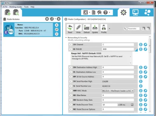
The Xbee Modules were configured by using X-CTU, which is the official program that Digi, the entity behind the Xbee, provides, in which the user is presented with a graphical interface, presented in Figure4.8, to manage and configurate Xbee Modules.
Figure 4.8: X-CTU Interface
To set up a network that enables the modules to communicate with each other, there are several steps, similar in each module, that must be followed.
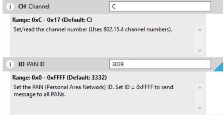
The first step when configuring the Modules is to set the Channel number and the Personal Area Network (PAN) Identifier, both being the same for each module, an example of the procedure is shown on Figure4.9.
Figure 4.9: 802.15.4 Channel number And PAN Identifier
Afterwards, the baud rate is set to the chosen value, 9600, which is the default value on each of the Xbee Modules. This configuration is shown in Figure4.10
Figure 4.10: Setting the Xbee Baud Rate
Finally, one must choose the mode of operation, shown in Figure4.11, which was, as previ-ously explained, API Mode 2, with escaped characters.
Figure 4.11: Xbee Mode of Operation Selection
Moreover, the X-CTU also enables users to check the module’s 64-bit address, as shown in Figure4.12.
4.4 Central Coordinator Node 35
Figure 4.12: Xbee IEEE Module Address
As previously stated, there was the need to disable the 16-bit address of each Xbee Module, this was done by setting the MY Value to 0xFFFF, as shown in the Figure4.13.
Figure 4.13: Disabling Xbee 16-bit address
To check if the modules are working correctly, the X-CTU provides us with a terminal, which can be used to send or receive various types of messages, therefore, enabling the exchange of messages between several Xbee Modules.
4.4 Central Coordinator Node
According to the system architecture presented in chapter3.3, the basic functioning of the CCN consists of:
• Establishing connection to the internet and the database;
• Accept communications from multiple SANs, replying immediately once a message is re-ceived, which is also described as a callback;
• Manage the SANs.
As such, this section focuses heavily on the software developed, further delving into the Inte-grated Development Environment (IDE) and libraries used, and the software’s organization. 4.4.1 Software
4.4.1.1 Cloud 9
The IDE chosen to developed the code for the CCN was Cloud 9, which is an open-source web based programming platform that supports several programming languages, and installed on the BBB by default.
Figure 4.14: Cloud 9 Interface
4.4.1.2 libxbee
One of the main issues with the Xbee Communications in API mode, is the increasing complexity in its implementation in comparison with AT mode. In order to facilitate said implementation, there are several Libraries, some officially backed by Digi, while others are developed by the Xbee Community. Given that this project is being developed with C/C++ languages, the choice fell on libxbee. Its files are available for download on [27]
This library provides users with a simpler way to interact with the Xbee Modules in both its API submodes, making it easier to construct, receive and analyse data packets.
For the development of the software, the following functions defined on the library, and with further characterized in [28] were used:
• xbee_conNew() - Creates a new connection to the Xbee Module, by specifying the connec-tion type and the module’s address;
• xbee_conSettings() - This function is used to configure the module’s settings, such as catch-ing all packets, enable broadcastcatch-ing, or disable acknowledges;
• xbee_conCallbackSet() - Sets a callback function associated with an established connection; • xbee_conCallbackGet() - Retrieves data acquired from the callback set with a connection; • xbee_conTx() - It is used to send a message to a module with an established connection;
![Figure 2.8: A Sensor/Actuator Node From A Case Study Presented In [4]](https://thumb-eu.123doks.com/thumbv2/123dok_br/18794011.925369/28.892.223.637.601.827/figure-sensor-actuator-node-case-study-presented.webp)
![Figure 2.10: WebLab 3-level architecture as presented in[13]](https://thumb-eu.123doks.com/thumbv2/123dok_br/18794011.925369/30.892.187.648.614.880/figure-weblab-level-architecture-as-presented-in.webp)

![Figure 2.15: Components Of A Database System With SQL As Presented In [20]](https://thumb-eu.123doks.com/thumbv2/123dok_br/18794011.925369/35.892.289.651.804.950/figure-components-database-sql-presented.webp)