outubro de 2019
Cristiano António Azevedo Rodrigues
Heterogeneous Fault Tolerance
Architecture based on Arm and
RISC-V Processors
outubro de 2019
Cristiano António Azevedo Rodrigues
Heterogeneous Fault Tolerance
Architecture based on Arm and
RISC-V Processors
Dissertação de Mestrado
Mestrado em Engenharia Eletrónica Industrial e Computadores
Sistemas Embebidos e Computadores
Trabalho efetuado sob a orientação do
Professor Doutor Adriano José Conceição Tavares
Professor Doutor Sandro Emanuel Salgado Pinto
DIREITOS DE AUTOR E CONDIÇÕES DE UTILIZAÇÃO DO TRABALHO POR TERCEIROS
Este é um trabalho académico que pode ser utilizado por terceiros desde que respeitadas as regras e boas práticas internacionalmente aceites, no que concerne aos direitos de autor e direitos conexos.
Assim, o presente trabalho pode ser utilizado nos termos previstos na licença abaixo indicada. Caso o utilizador necessite de permissão para poder fazer um uso do trabalho em condições não previstas no licenciamento indicado, deverá contactar o autor, através do RepositóriUM da Universidade do Minho.
Atribuição-NãoComercial-CompartilhaIgual CC BY-NC-SA
Em primeiro lugar, gostaria de expressar a minha mais profunda gratidão pelo o apoio e contínuo suporte que o meu orientador e professor, doutor Adriano Tavares, me providenciou ao longo deste árduo último ano. Todo o conhecimento passado e pensamento crítico por ele incutido, vieram-se a demonstrar fulcrais ao longo de toda a dissertação. Ainda no âmbito de orientação académica, gostaria também de agradecer toda a ajuda, apoio e críticas construtivas providenciadas pelos professores doutores Sandro Pinto e Tiago Gomes assim como pelo aspirante a doutor, José Martins.
Não poderia deixar de agradecer aos meus colegas de laboratório, Afonso Santos, André Alves e Ricardo Moreira assim como aos meus amigos mais chegados, que foram parte integrante desta minha longa caminhada, tendo eles passando comigo todos os melhores “altos” e dando-me suporte nos meus piores “baixos”. Um especial obrigado a todos os membros do “bando”: Daniel Barbosa, José Silva, José Pedro, Ivo Marques e Valter Mário.
Por fim, endereço um especial agradecimento a toda a minha família. Família essa que fez e faz com que tudo isto tenha um sentido e propósito. Por toda a crença, apoio e suporte incondicional um obrigado para minha mãe, para o meu pai, para os meus irmãos, André e Sandrina, e para o meu cunhado, Senhor Dr. João Ribeiro. Deixo aqui, para uma futura leitura, um agradecimento ao recém-nascido João Salvador, pela inconsciente, mas poderosa extra motivação trazida para a “espinhosa” reta final.
A todos os que fizeram esta caminhada possível, um forte obrigado do fundo do meu coração.
I hereby declare having conducted this academic work with integrity. I confirm that I have not used plagiarism or any form of undue use of information or falsification of results along the process leading to its elaboration.
I further declare that I have fully acknowledged the Code of Ethical Conduct of the University of Minho.
Arquitetura Heterogénea de Tolerância a Falhas Baseada em processadores Arm e RISC-V
Quando sistemas críticos operam em ambientes hostis, estes necessitam de serviços de redundância e de tolerância a falhas para continuarem em funcionamento mesmo na presença de faltas. Embora a técnica de tolerância a falhas seja eficaz para mitigar faltas que ocorrem num único componente, ela perde eficácia, quando múltiplas faltas acontecem simultaneamente em vários componentes. Estes tipos de faltas, despoletam o mesmo erro em todos os componentes afetados, tornando-as indetectáveis. Para solucionar este problema, usualmente, recorre-se a diversidade de desenho para mitigar as Falhas de Modo Comum (FMC), construindo assim um sistema mais robusto e confiável. Várias arquiteturas de tolerância a falhas, baseadas emField-Programmable Gate Array (FPGA), têm sido descritas na literatura, no entanto, pelas pesquisas efetuadas, nenhuma delas tem como objetivo proteger processadores het-erogéneos e aplicar diversidade de desenho ao nível do processador.
Para resolver a supracitada falta de soluções, esta dissertação propõe uma nova arquitetura het-erogénea de tolerância a falhas, Lock-V. O Lock-V promove diversidade de desenho, ao nível da arquitetura do processador, assim como técnicas de tolerância a falhas para, respetivamente, mitigar FMC e detetar e recuperar erros despoletados por causas externas, por exemplo, radiação. Para eliminar as FMC, o Lock-V possuí duas unidades de processamento diferentes: umhard-coreArm Cortex-A9 e umsoft-corebaseado em RISC-V. Desta forma é aplicada diversidade de desenho, usando heterogeneidade noInstruction Set Architecture (ISA). Por outro lado, para implementar tolerância a falhas, o Lock-V propõe uma solução híbrida de Dual-Core Lockstep (DCLS), onde a deteção de erros é feita em hardware, recorrendo a um acelerador na FPGA, e a recuperação dos erros é suportado porsoftware, usando técnicas derollback.
Após o Lock-V ser implementado na Zynq-7000System-on-Chip (SoC), mais de 45000 faltas foram injetadas. Os resultados dessa injeção mostram que quando uma aplicação executa na arquitetura Lock-V, para além de estar protegida contra FMC, devido à diversidade do desenho ao nível dos processadores, também está protegida contra 97% dos erros ocorridos. No entanto, implementar o Lock-V acarreta alguns tradeoffs. 79% dasLook-Up Tables (LUT)e 34% dosFlip-Flops (FF)disponíveis na plataforma (Zedboard), são usados. Ao nível dosoftware, o Lock-V aumenta em 8% o consumo de memoria e, para o pior cenário testando sem a ocorrência de erros, aumenta em 12% o overhead de execução. Tendo em conta que toda a redundância tem o seu custo, o Lock-V provou ser capaz de dotar um sistema com diversidade de desenho e capacidades de tolerância a falhas.
Palavras chave: diversidade de desenho,lockstep, redundância, tolerância a falhas. vi
Heterogeneous Fault Tolerance Architecture based on Arm and RISC-V Processors
Safety-critical systems deployed in harsh environments rely on fault tolerance and redundancy tech-niques to keep them operating even in the presence of faults. Although there are effective techtech-niques to mitigate one side faults, they are not enough to protect the system against simultaneously multi side faults. These kinds of faults trigger the same error in faulty redundant components, which makes resulting errors invisible and undetectable for fault tolerant mechanisms. To overcome this problem, design diversity is applied in fault tolerant system to mitigate the Common-Mode Failure (CMF) and build a more robust and reliable system. Despite several fault tolerance architectures based on FPGA are available in the literature, to the best of our knowledge, none of them aims both hardening of heterogeneous processors and applying design diversity at processor level.
To address this lack of solutions in the current state of the art, this dissertation proposes a novel het-erogeneous fault tolerance architecture, Lock-V, which enables design diversity at processors architecture level. It deals with CMF, as well as both error detection and recovery fault tolerance techniques to mitigate errors triggered by external environment interactions, e.g., radiation. To eliminate the CMF, Lock-V ex-plores an implementation based on different processing units: a hard-core Arm Cortex-A9 and a soft-core RISC-V-based processors, to leverage design diversity through ISA heterogeneity. To implement fault toler-ance, Lock-V proposes a hybrid DCLS solution where the error detection is done by hardware, resorting to a FPGA accelerator, while error recovery is performed by software using rollback technique.
After the deployment of Lock-V on a Zynq-7000 SoC, over 45000 faults were injected. The results taken from such injection shows that when an application runs on the Lock-V architecture, besides its protection against the CMF due to processors design diversity, it is also protected against 97% of the triggered errors. Nevertheless implement Lock-V came up with some tradeoffs. It used 79% of the LUT and 34% of the FF available on the Zedboard FPGA platform. Regarding the software part, implementing Lock-V leads to an 8% increase in memory footprint and also an increase in the execution overhead around 12%, mainly in the worst case scenario as tested in the absence of errors. Knowing that all the redundancy has its cost, Lock-V proved to be able to grant a system with design diversity and fault tolerance capabilities.
Keywords: design diversity, fault tolerance, lockstep, redundancy.
List of Figures xi
List of Tables xii
List of Listings xiii
Acronyms xiv
1 Introduction 1
1.1 Motivation . . . 2
1.2 Goals . . . 2
1.3 Document Structure . . . 3
2 Background, Context and State of the Art 5 2.1 Dependability . . . 5 2.1.1 Dependability Attributes . . . 6 2.1.1.1 Reliability . . . 6 2.1.1.2 Availability . . . 6 2.1.1.3 Safety . . . 7 2.1.2 Dependability Threats . . . 8
2.1.2.1 Fault, Error, Failure . . . 8
2.1.2.2 Causes . . . 9 2.1.3 Dependability Means . . . 9 2.1.3.1 Fault tolerance . . . 11 2.2 Redundancy . . . 12 2.2.1 Hardware Redundancy . . . 13 2.2.2 Software Redundancy . . . 13 2.2.2.1 Time Redundancy . . . 13 2.2.2.2 Spatial Redundancy . . . 13 2.2.3 Information Redundancy . . . 14 viii
2.2.4.2 Triple Modular Redundancy . . . 15
2.2.5 Redundancy to achieve Fault-Tolerance . . . 15
2.2.5.1 Design diversity . . . 17
2.3 Lockstep . . . 17
2.3.1 Design Diversity Applied To Lockstep . . . 19
2.3.2 Lockstep Implementations . . . 20 2.3.3 Discussion . . . 24 3 Platform 26 3.1 Processors . . . 26 3.1.1 The lowRISC . . . 28 3.2 ZedBoard . . . 30
4 Proposed Architecture (Lock-V) 32 4.1 Adding Lockstep Capabilities . . . 32
4.2 Architecture Overview . . . 34
4.3 The lowRISC Adaptations . . . 36
4.3.1 Adding A New Peripheral . . . 36
4.4 xLockstep . . . 37
4.4.1 Synchro . . . 38
4.4.2 LIFO . . . 40
4.4.3 Checker . . . 41
4.4.4 xLockstepAXI-aware Interface . . . 41
4.5 xLockstepdeployment in Lock-V . . . 43
4.6 xLockstepAPI . . . 44
5 Lock-V Framework 48 5.1 Framework Overview . . . 48
5.2 Error Detection Capabilities . . . 50
5.2.1 Checkpoint . . . 50
5.3 Error Recovery Capabilities . . . 51
5.3.1 Save Processors’ Context . . . 52
5.3.2 Rollback Processors’ Context . . . 53
5.4 Framework Constraints . . . 54
6.1 Lock-V PL Resources Utilization . . . 57
6.2 Lock-V Framework Costs . . . 58
6.2.1 Memory Footprint . . . 58 6.2.2 Execution Footprint . . . 59 6.3 Case study . . . 62 6.3.1 Setup . . . 62 6.3.2 Fault Injection . . . 63 6.3.2.1 Results . . . 64 7 Conclusion 66 7.1 Future Work . . . 67 References 68 x
2.1 Fault tolerant system with error detection and error recovery. . . 11
2.2 Representation of a system with DWC, adapted [1]. . . 15
2.3 Representation of a system with TMR, adapted [1]. . . 16
2.4 Transaction Architecture block diagram [2]. . . 23
2.5 Proposed loosely DCLS architecture implemented in the Zynq-7000 APSoC [3]. . . 24
3.1 Tethered and untethered implementations based on the Rocket chip. . . 29
3.2 ZedBoard development board. . . 30
4.1 Design options for the lockstep architecture. . . 33
4.2 Proposed DCLS heterogeneous architecture. . . 34
4.3 Design of thexLockstepaccelerator with its modules and sub-modules. . . 38
4.4 Main FSM of thexLockstep. . . 39
4.5 ThexLockstepperipheral memory address space. . . 42
4.6 Lock-V design (Arm side). . . 44
4.7 Control register field. . . 47
4.8 Status register field. . . 47
5.1 Flow execution of an application running in Lock-V, coded using the Lock-V framework. . 49
5.2 Flow execution of the checkpoint tool. . . 50
5.3 Example of the Arm save processor’s context. Although the number of registers and stack alignment are different, the logic in the RISC-V save processor’s context is the same. 53 5.4 Example of the Arm rollback processor’s context. Although the architecture is different, the logic behind the RISC-V rollback processor’s context is the same. . . 55
6.1 Fault injection setup. . . 62
6.2 Fault injection mechanism. . . 63
6.3 SDC errors after the injection of faults with and without the Lock-V. . . 65
6.4 Hang errors after the injection of faults with and without the Lock-V. . . 65
2.1 Dependability table of concepts. . . 6
2.2 Availability percentage corresponding to the different systems types. . . 7
2.3 Dependability means and their use cases during the lifetime of a system. . . 10
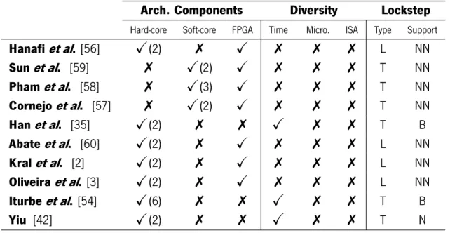
2.4 Gap analysis among Lockstep implementations. . . 25
3.1 Soft-Core Candidates Analysis. . . 27
6.1 Post-Implementation results obtained from Vivado 2016.2. . . 58
6.2 Arm memory footprint in bytes. . . 59
6.3 RISC-V memory footprint in bytes. . . 59
6.4 saveContextandrollbackexecution footprint. . . 60
6.5 Checkpointexecution footprint in clock cycles. . . 61
6.6 Lock-V execution footprint with and without an error in clock cycles. . . 61
6.7 Fault injections testes with and without Lock-V. . . 64
4.1 New entry added into lowRISC address map, changing the chisel file
$TOP/src/main/s-cala/Configs.scala. . . 36
4.2 New NASTI-Lite interface added to the NASTI-Lite crossbar, changing the SystemVerilog file $TOP/src/main/verilog/chip_top.sv. . . 36
4.3 LIFO Module interface, which was implemented in chisel. . . 40
4.4 Signals for restrict the access to the Arm registers bank. Two equal signals were used in the RISCV Advanced Extensible Interface (AXI)-Lite interface. . . 43
4.5 Internal API function for read a MMIO peripheral register. . . 45
4.6 Internal API function for write in a MMIO peripheral register. . . 46
4.7 Internal API function for write in a bit of a MMIO peripheral register. . . 46
ABI Application Binary Interface
ADAS Advanced Driver-Assistance Systems
ALU Arithmetic Logic Unit
AMBA Advanced Microcontroller Bus Architecture
API Application Programming Interface
ASIC Application Specific Integrated Circuits
AXI Advanced Extensible Interface
BIST Built-In-Self-Test
BRAM Block Random Access Memory
CMF Common-Mode Failure
COTS Commercial Off-The-Shelf
CPU Central Processing Unit
DCLS Dual-Core Lockstep
DDR Double Data Rate
DMR Dual-Modular Redundancy
DWC Duplication With Comparison
ECC Error Correcting Code
EDAC Error Detection And Correction
FF Flip-Flops
FIC Fabric Interrupt Controller
FIFO First In First Out
FMC Falhas de Modo Comum
FP Frame Pointer
FPGA Field-Programmable Gate Array
FSM Finite State Machine
GP Global Pointer
GPIO General-Purpose Input/Output
I/O Input/Output
I2C Inter-Integrated Circuit
ISA Instruction Set Architecture
L2C Locked L2 Cache
LIFO Last In First Out
LR Link Register
LUT Look-Up Tables
MBU Multiple Bit Upset
MCU Microcontroller Unit
MMIO Memory-Mapped Input/Output
MMR Multiple-Modular Redundancy
MMUs Memory Management Units
MTBF Mean Time Between Failures
MTTF Mean Time To Failure
MTTR Mean Time To Repair
NASTI Not A Standard Interface
OCM On-Chip Memory
PC Program Counter
PL Programmable Logic
PR Partial Reconfiguration
PS Processing System
RA Return Address
RAM Random Access Memory
RCU Reconfigurable Computing Unit
RISC Reduced Instruction Set Computer
SBU Single Bit Upset
SCU Snoop Control Unit
SDC Silent Data Corruption
SEE Single Event Effect
SEFI Single Event Functional Interrupt
SEL Single Event Latch-up
SET Single Event Transient
SEU Single Event Upset
SHIFT Software-Implemented Hardware Fault Tolerance
SoC System-on-Chip
SP Stack Pointer
SPI Serial Peripheral Interface
TP Thread Pointer
UART Universal Asynchronous Receiver Transmitter
VP Verification Point
WFE Wait For Event
Processors industry keeps moving fast towards reduced transistor’ size, higher clock frequencies, and lower operating core voltages. However, many problems to digital systems have emerged due to such progress, like system failures caused by bit-flipping induced by many possible sources, e.g., radiation. These problems can result in critical issues, not only in aerospace applications, but also in daily basis systems [4, 5, 6, 7, 8, 9]. This boosts research towards developing and deploying fault tolerance systems in order to mitigate several failure situations, while keeping other important requirements such as system robustness, reliability, performance and security.
One way to deploy reliable devices in mixed-critical applications, is to provide them with fault tolerance techniques. Redundancy is one of the most used forms of fault tolerance mechanisms and several solu-tions can be already found in the literature. While some techniques replicate processing units in a technique called DCLS — implemented either loosely- or tightly-coupled to the processor — [10, 7, 11, 12, 13, 2], others apply a Triple Modular Redundancy (TMR) mechanism, where the processing units are triplicated and a voter module is added to the system [14]. Other techniques can be used in order to achieve fault tol-erance systems, such as time redundancy applied to low-cost architectures [15], and virtualization-based systems [16], [17], [18], [19], where several guests can virtually run over the same processing unit as if they were individually running in one unique processor. This way, each guest operating system (OS) can replicate the execution of the same software application, while another guest acts as the voter module. These software-based systems can behave similar to a hardware-based TMR without the need of replicating the hardware resources.
Fault tolerance has proven to be effective in the detection and recovery of errors due to physical faults, e.g., bit-flips by radiation, however, it is vulnerable to either human-made design faults [20] or external disturbances, that affects more then one redundant component at the same time [21]. This type of system’s failures called CMF, e.g., power supply disturbances, manufacturer defects, software bugs in tools/compilers, among others, can only be mitigated using design diversity. Design diversity was proposed in [20] in order to protect fault tolerant systems against CMF and is described as ” the approach in which the hardware and software elements that are to be used for multiple computations are not copies, but are independently designed to meet a system’s requirements ”. Nowadays, safety critical systems are aware of the need of design diversity to deal with CMF. To protect the processors against the common-mode failure and build a high-reliability systems, several techniques have been proposed. The design diversity on these
systems is usually applied targeting time diversity — which introduce a execution cycle delay among the processors [22] — but sometimes it can also be implemented with microarchitectural diversity [23] or even ISA diversity [24].
Fault tolerance techniques can be performed both in software and/or hardware, according to the available resources. With the ongoing technological trends, hybrid SoC solutions provide software pro-grammability, available through the hard-core processors, and FPGA technology that can be resorted to deploy soft-core processors or dedicated hardware accelerators in order to enhance the computation of several types of algorithms in terms of speed and energy consumption [25, 26]. These heterogeneous SoC, composed by a hard-core plus a soft-core, make easier the development of a fault tolerant reliable system endowed with design diversity at the ISA level.
1.1 Motivation
Increasingly safety has become a must in the majority of the daily basis commercial systems which consequently, leads to an increase in the demand for fault tolerance systems. This high demand will boost the developing of new architectures and new systems with fault tolerant capability. This opens opportunities to research new techniques and approaches for implementing high-reliable and safety systems, which specially motivated me to jump in this research journey.
Another really interesting point is that, we are in the golden age of processors architectures with the appearance of open-source ISAs like the RISC-V that gives a new level of software and hardware freedom on architectures in an open extensible way, e.g., to develop custom instructions and tightly-coupled co-processors. This, altogether with the high availability of hybrid SoC FPGA-based in the market, brings huge architecture flexibility to explore, develop and delivery fail-functional systems. Despite several architectures and techniques for fault tolerance being available in the literature, to the best of our knowledge, none of them targets heterogeneous architectures that resort hybrid SoC solutions to implement different processor architectures, either deployed in hard- or soft-cores. This is a a kind of ”blue ocean” waiting for being explored.
1.2
Goals
The project developed on this thesis aims to provide an environment for a user to create and run its application in a fault tolerant fashion. After a comprehensive literature review, as exposed in Section 2.3, three main goals were established for this thesis:
1) Develop an architecture on which an application will run in a safety manner based on redundancy techniques to implement fault tolerance;
2) Develop a framework that allows the use of the proposed architecture and recovery the system from errors;
3) Develop a fault injection mechanism that will test the proposed architecture as well as its framework. In order to achieve the three main goals, some more specific objectives were drawn. They are pre-sented in the following topics.
To reach the first goal
It is necessary to harden the processors on the architecture using a technique called lockstep. This technique should be deployed as a FPGA accelerator and process information in parallel as well as ac-cessing the redundant cores simultaneously. This accelerator needs also to have synchronizations and error detection capabilities, in order to compare at the same execution point the processors’ outputs and detect errors (if they exist). The architecture should be also aware of the leveraged design diversity to mitigate CMF.
To reach the second goal
First the framework should be agnostic to the processor’s architecture. This means that an application written for the framework, can be compiled either for Arm or RISC-V processors without changing the code. The framework needs to self adapt to the processor architecture. Second, the framework needs to be developed towards a fail-function system, which still keeps delivering its services in the presence of a fault. The system needs to implement techniques for fault resilience and recovering the system to a healthy state when an error is active. To achieve this the the framework have to provide three main functionalities:
• Allow the user (programmers) to choose verification’s points in the code where the architecture error detection capabilities will be applied.
• Save a healthy system’s state;
• Perform a rollback, recovering the system from an erroneous state to the previous saved system healthy state;
To reach the third goal
The fault injection mechanism should emulate harsh environments where the incidence of radiation cause faults. For doing that, the mechanism must inject faults similar to those occurring in the harsh environments.
1.3
Document Structure
The document of this thesis is structured as follows. Chapter 2 overviews the basic concepts around fault tolerance. It starts to contextualize the fault tolerance and explaining why it is needed. Afterwards it
expose methods that can be used to achieve fault tolerance through redundancy techniques. At the end of the chapter a survey is presented regarding the lockstep implementations in the current state of the art. Chapter 3 presents some requirements that were followed to choose the soft-core as well as the platform constraints imposed by the chosen soft-core. Finally, it presents the chosen platform to deploy the pro-posed architecture. Chapter 4 proposes the Lock-V, a fault tolerance heterogeneous architecture exposing its design and implementation. Chapter 5 addresses the design and implementation of the framework sup-porting Lock-V through auxiliary tools for the development of application under the proposed architecture. Chapter 6 presents and discusses the system evaluation as well as the fault injection mechanism that was designed and implemented. The last but not the least, Chapter 7 summarizes the thesis presenting its constraints and limitations as well as the future improvements.
of the Art
As the main subject of this thesis is fault tolerance, this chapter will first contextualize the general definition around fault tolerance and its purpose. After that, it will be explain how fault tolerance can be implemented, followed by some work done in this area. Even though there are many types of redundancy as well as implementations, the focus will be on architectures based in FPGA, using dual-core lockstep for hardened the processors on the architecture, e.g., [3] and [2]. In the section about dependability and redundancy the basic terminologies and concepts are explained for a better understanding of the fault tolerance implementation in the thesis project as well as the need for design diversity in a fault tolerant system. The chapter finishes with a comprehensive analyses of lockstep implementation in current sate of the art as well as a literature gap analysis.
2.1
Dependability
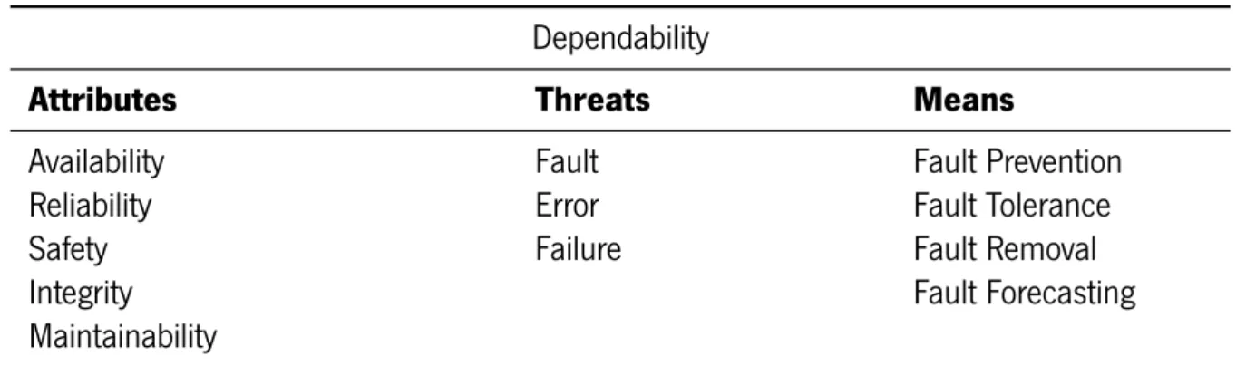
The system dependability is defined as the system ability to avoid service failures that are more frequent and more severe than is acceptable [27]. This concept describes the means used to deal with the threats in order to do not compromise the system reliability. Table 2.1 represents the three basic notions inside the dependability concept. In the first column the dependability attributes are depicted, which are defined as the properties that a dependable system must own. In the next column the dependability threats are represented, which are defined as the reasons for a system to spot performing its function. The threats should be avoided or, in case of being unavoidable, it is needed to deal with them and minimize their consequences. For that reason, it is necessary methods for dealing with the threats. This set of techniques, as shown in the last column, are possible means or approaches for mitigating threats. The approaches can be either preventive or curative. If they avoid the threat and act before they occur, then they are preventive. If they deal with the threats after they occur, they are curative ones. In the following topics 2.1.1, 2.1.2 and 2.1.3 this concept will be explained in more detail.
Table 2.1: Dependability table of concepts.
Dependability
Attributes
Threats
Means
Availability
Fault
Fault Prevention
Reliability
Error
Fault Tolerance
Safety
Failure
Fault Removal
Integrity
Fault Forecasting
Maintainability
2.1.1
Dependability Attributes
The dependability attributes define the properties that a system is expected to have [1]. The five dependability attributes are defined by Avizieniset al. [27] as: (1) availability, readiness for correct service; (2) reliability, the system’s ability to deliver a correct service in a continuous manner; (3) safety, absence of catastrophic consequences to the system external environment, both for the user(s) and the environment; (4) integrity, absence of improper system changes; and (5) maintainability, system’s ability to be repaired and modified. Although dependability only makes sense when all attributes are part of system properties, in most cases the first three attributes, availability, reliability, and safety have the primary focus. In the following topics, each of these three attributes will be explained in more detail.
2.1.1.1 Reliability
Reliability is the probability of a system to perform without any failure for a given interval of time. Thus, the reliability represents a measure of time between the instant zero, when the system is in a fully functional state, and the next expected system failure [1]. This time is known as Mean Time To Failure (MTTF) [28]. In some situations (e.g, harsh environments, remote/inaccessible places) is required a high-reliability system that has to operate in a non-stop fashion. Such systems has to ensure that the delivery service is not degraded, even if some faults occurred. High-reliability systems, like power plants control system, space missions, heart pacemakers, can have faults and still be reliable. Such systems must prevent fault propagation, as they are always safe if no fault is propagated to a system failure. This is possible because high-reliability systems own mechanism to avoid the propagation of the faults. Later in Section 2.1.3 these mechanisms of fault mitigation will be addressed more in detail.
2.1.1.2 Availability
System availability is the probability that the system will function correctly at a given time or period [1]. In order to determine the system availability, it is necessary to know the Mean Time To Repair (MTTR), which is the time since one fault was detected until its full mitigation [28]. Availability is the ratio of the time
a system meets its specification and the elapsed time. Another important concept related to availability is the downtime per year. This represents the time of system’s inoperability throughout one year for a given percentage of availability. Based on it systems are classified according to their availability, from unmanaged to ultra available. Systems are sometimes referred in terms of the number of nines that the percentage of availability owns. Table 2.2 depicts the availability of one system for a continuous operation during one year as well as its downtime, class (”class of nines”) and system rating.
Table 2.2: Availability percentage corresponding to the different systems types.
System Type
Downtime
Availability
Class
Rating
Unmanaged
35.53 days
90%
1
Managed
3.65 days
99%
2
Routine
Well Managed
8.77 hours
99.9%
3
Essential
Fault Tolerant
52.6 minutes
99.99%
4
High Availability
5.26 minutes
99.999%
5
Critical
Very High Availability 31.56 seconds
99.9999%
6
Ultra Availability
3.16 seconds
99.99999%
7
Safety-Critical
2.1.1.3 Safety
Safety is the absence of catastrophic consequences when one or more faults occur, preventing user damage and environment disasters [27]. This is an important requirement for safety-critical systems. If these systems fail they can either cause harm for the users, e.g., hearts stops beating if a pacemaker fails, or for the surrounding environment, e.g., radiation release if a nuclear power plant had a failure. Safety-critical systems need to have a safety failure mode. This failure mode must analyze, describe and then prevent, in case of a severe failure has occurrence, any damage caused to other equipment, people or to the environment. Despite this, a system can fail and stop its operations and still be safe. A safe system not necessarily implies that the system will continue operating after a fail. If the system when stops operating does not cause dangerous situations, it remains safe. However, if a system stop implies safety issues, it must not stop working at all. For example, the flight control system onboard an F-16 is only a safe system meanwhile the failure does not cause the loss of system functionalities. If the system fails and stops operanting, the F-16 falls down. In terms of safety, a system can has one of the following failure modes:
• fail-unsafe: a fail may cause safety hazards that may lead to user or environment harms; • fail-safe: after a failure, the system switches to a safe operating mode with reduced functionality
(there are degradation of the delivered service). One example of this failure mode is an elevator. If its cable breaks down, the brakes are applied and the elevator is stopped, avoiding that falling down. The system stop delivery its function, transport people between floors, but remains in a safe state being a safety system;
• fail-functional or fail-operational: the system keeps fully functional without any degradation of the delivered service for a certain number of faults. An example of a fail-operational system is the flight control system on a F-16 board, that is quadruple redundant. This means that it owns four fully functional replicas of the system that can start operating at any time, while only one would be required. In this mode of failure, the system may fail and still continue to provide its functionality safely.
2.1.2
Dependability Threats
The dependability threats are usually defined as fault, error, and failure. These threats are what compromise the functionality of a system. This may cause the system to deviate the current service from the previously specified service (its main purpose) preventing it from being delivered. This threats also undermines the system dependability attributes (mentioned in Section 2.1.1.).
2.1.2.1 Fault, Error, Failure
It is important to understand the concepts of fault, error, and failures and how can they trigger a fault tolerance system to recover successfully from failure situations caused by errors. A fault tolerance system must continue to provide the specified service, even at the event of a fault, and should react to errors caused by faults, preventing the error propagation to a state of system failure. In [27] Avizienis et al. provides the main concepts and taxonomy for the dependability threats:
• Fault: is defined as a logical manifestation caused by one or more physical defects, which change the normal operation of a component in a system;
• Error: is caused by one or more faults in a system when it transits into an internal state;
• Failure: occurs when some event deviates the delivered service from the specified service. A specified service is defined as a previously agreed description of the system behavior.
Faults can be classified according to many criteria. Regarding the domain, there are hardware or software faults. In terms of their causes, they can be divided into three groups [27]: (1) development faults that include all the faults that are introduced in the system during the design time; (2) physical faults that include all faults that affect hardware; and (3) interaction faults that include all external faults caused by interaction with the environment and/or the user. The software faults are predominantly caused by development faults. A software without development ”bug” works uninterruptible without gives an error and has a software failure. The software can stop working, but just in the case of the hardware (i.e. the memory, processors, etc) also stop working. The hardware fault can be due to a physical or an interaction fault and indirectly tamper with the data or the program in execution. Therefore, the software faults are always permanent, because they always result from development errors [29]. On the other hand, hardware faults are predominantly affected by physical faults and interaction faults (may be affected as well for development faults, but derived from the maturity of the hardware design this rarely happens).
Hardware faults are classified according to their durations into three groups [1]: permanents, transitory and intermittent. The permanent faults are caused by physical defects of the hardware. The transitory faults are triggered by unique events that affect the hardware, known as Single Event Effect (SEE). This can create hard- or soft-errors. In the case of a soft-error occurs, the SEE hit the hardware and just change its state without permanently damaging it. The hardware can be recovered moving to a fully operational state. In another case, when a hard-error occurs, the hardware stays damaged forever. This happens, for example, when there is a bit-flip, and it is never possible to write again to the bit that has been hit. In contrast, when a bit-flip happens due to a soft-error, the bit can be rewritten. The last-mentioned type of faults, the intermittent ones are transitory faults that occur periodically.
2.1.2.2 Causes
The transitory faults can be caused by several reasons. One of them is through the incidence of radiation. This radiation effects called SEEs can be either nondestructive or destructive [30]. SEEs can originate four different types of effects: (1) Single Event Latch-up (SEL); (2) Single Event Transient (SET); (3) Single Event Functional Interrupt (SEFI); and (4) Single Event Upset (SEU). What sets them apart is their cause. Each is triggered when a specific system component is affected by radiation. The SEE can cause permanent damage to the system, destructive SEE or hard SEE, or cause transitory damage that can be recovered, nondestructive or soft SEE. Out of the four above mentioned SEE, one of them can originate a hard SEE and three of them a soft one. The SEL is what causes the hard SEE. This happens when a particle hits a MOSFET or transistor oxide, triggering their gates and hence activating the latch. The three events that causes a soft SEE are the SET, SEFI and SEU. The SET is one of the three events that can originate a soft SEE, and it is characterized by the changing of the expected logical/combinational circuit behavior [31]. When a particle hits. the circuit may charge the P-N junction of the semiconductor and generate current pulses that may affect the MOS transistors and later the circuit behavior. The SEFI generates a system failure, e.g., when the particle hits a bit and generates an improper system interrupt or when the particle hits a bit that triggers a system self-test. In this case, the system goes into an improper self-test which is only solved by a system reboot. The last out of three soft SEE, the SEU, occurs when a particle hits a memory region and changes the value of that location without damaging it. For example, when a particle has flip a bit, a whole byte changes its value. The SEU is known in the literature as a soft error [30] and can has two nuances: (1) it can be a Single Bit Upset (SBU) in case of the radiation just hits a single bit; or (2) it can be a Multiple Bit Upset (MBU) when high energetic radiation hits a memory region and occurs a bit-flip of two or more bits [30].
2.1.3
Dependability Means
Dependability means are methods and techniques for mitigating the threats (Section 2.1.2) and so, delivering a dependable system. For building a dependable system two groups of techniques can be used, the fault avoidance or fault acceptance. They aim for different purposes and deal with faults in a
different manner. The first group of techniques, fault avoidance, tries to avoid the occurrence of a fault, e.g., through preventive maintenance. In contrast, the second group of techniques, the fault acceptance, does not prevent the faults, instead it accepts and isolates them. Thus, the faults are prevented from reach the system boundaries and propagate to errors and, consequently, to failures. The two groups of techniques deal with the threats in different manners. The techniques can be applied in pre-service, during the design-, implement- and test-time, or in-service during the operational lifetime of the system. A system can be made dependable endowing it with four types of techniques: fault preventing, fault removal, fault forecasting, and fault tolerance. Table 2.3 presents those techniques as well as their uses cases according to the phase in the system lifetime.
The Dependability means are described as follows:
• Fault preventing is composed by design techniques that can be used during the design-time when the specification, implementation, and fabrication stages are planed;
• Fault Removal can be performed either throughout the pre-service or service time. In pre-service, it is applied for testing and debugging the system in order to find faults in the system. This is done using three steps: (1) verification if the system functionalities match its specifications; (2) a diagnosis that comprises the identification of the faults and what cause those faults; and (3) the correction (removal) of the faults. The second possible use case of fault removal technique is during system service. It can be performed through preventive maintenance, where the systems’ components are replaced before they fail.
• Fault Forecasting aims the detection of present faults and predicting futures ones, to avoid their consequences. Fault forecasting performs the evaluation of the system behavior, resorting to some techniques like failure mode and effects analysis, Markov chains, stochastic Petri nets and fault-trees [27].
• Fault tolerance is a technique that ensures the correct function of the system within the presence of faults. This dependability approach will be used in this thesis, so it will be addressed in more detail in the next topic 2.1.3.1.
Table 2.3: Dependability means and their use cases during the lifetime of a system.
System Lifetime Phases
Reliability Means
Pre-Service (Development)
In-Service
Fault Preventing
Design and Implementation
7
Fault Removal
Test and Debug
Preventive Maintenance
Fault Forecasting
✓
✓
Fault Tolerance
7
✓
2.1.3.1 Fault tolerance
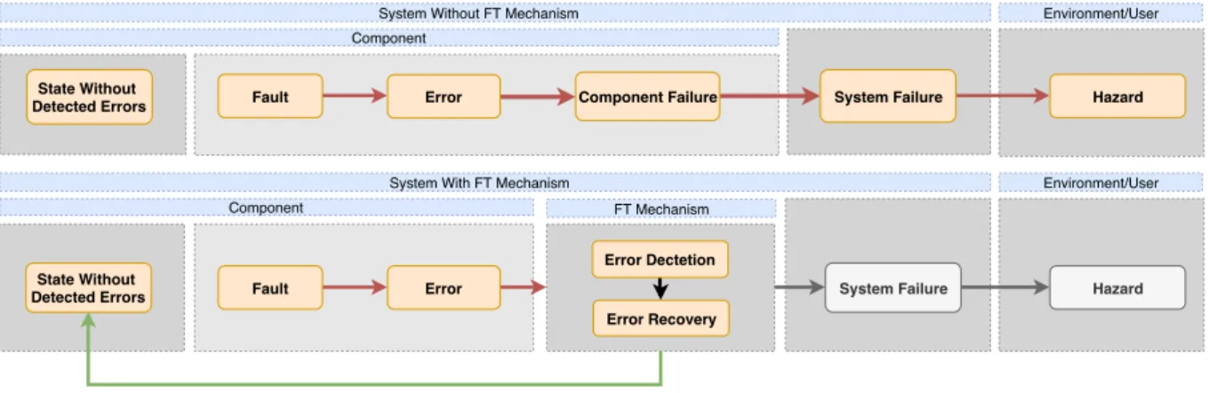
According to the defined dependability threats in Section 2.1.2, a fault is a malfunction in one compo-nent. That malfunction can lead the affected component to have an error that may propagate for a failure. Putting it simply, the failure of a component may lead to a system failure that causes dangerous system’s behavior. To avoid the occurrence of a system safety hazard, the chain of fault, error, and failure has to be interrupted. The fault tolerance ensures that the system functionalities do not degrade in the presence of active faults. Hence, fault tolerance techniques need to prevent the propagation of the fault to failures. The fault tolerance mechanism has to detect the errors and recovery the system from them before they reach the component boundaries. As depicted in Figure 2.1, the fault tolerance mechanism needs to perform its functions of detecting and mitigating errors while being an insurmountable fortress to prevent the error propagation. The barrier that prevents the error to be propagated is made up a mechanism in the fault tolerance component. That mechanism transforms, through recovery methods, a system from an error state to a state without detected errors. The fault tolerance mechanisms, as depicted in the Figure 2.1, need to own two functionalities, error detection and error recovery [27]. These functionalities may follow several conceptual implementations to achieve a fault tolerance system that can detect errors and recovery from them.
The first fault tolerance functionality, error detection, identifies the presence of an error in a system. It can be split into two methods: (1) concurrent detection, an online detector that works at the same time at the system delivers its service; and (2) the preemptive detection that is an offline detector, that works when the system suspends its service delivery.
The other fault tolerance functionality, error recovery, is responsible for removing the error and restore the system for one state without errors. This can be reached through two manners, error handling or fault handling. The error handling eliminates the error from the system using one of the following three techniques:
• Rollback: brings the system back to a fully functional state. The system is recovered through a system’s backup that occurred before the error was triggered. Afterward, the system goes back to
Component Failure
Component
Fault Error
State Without Detected Errors
System Without FT Mechanism
System Failure Failure Component Fault Error State Without Detected Errors
System With FT Mechanism
FT Mechanism
Error Recovery Error Dectetion
System Failure Hazard
Hazard
Environment/User
Environment/User
a state that owns no errors, and starts moving forward from there;
• Rollforward: changes the system from an erroneous state to a error-free state. This way, the system’s errors are mitigated and the system can keep move forward;
• Compensation: the system owns several redundancy mechanisms that can be enabled, masking errors when they occur.
The second error recovery technique, the fault handling, averts faults, which triggered errors, from being activated again through four possible manners:
• Diagnosis identifies the errors and determines the cause of their occurrence. The errors are cataloged in terms of ”where” they had occurred and ”how”, describing the type of error;
• Isolation: the faulty elements, which are responsible for triggering the error are excluded from the system. This method of fault handling makes the fault dormant, excluding the defective component from the system;
• Reconfiguration: either switches components from faulty to redundant ones or reassigns tasks among healthy components;
• Reinitialization: updates the system state and its configurations. It is done either by resetting the system to an initial state or just updating the system information/configuration without a reset. The above fault tolerance techniques are implemented in the systems according to their type, the needed degree of availability and the acceptable system downtime. The best-fit technique should be cautiously chosen. The hardware designers need to make tradeoffs when designing the system with these techniques. They have to have into account the level of the system dependability that is delivery versus the cost of the silicon area and engineering efforts that the implementation of the techniques requires.
2.2
Redundancy
Redundancy is the all addition system capabilities that would be unnecessary in a fault-free environ-ment. The main idea is to have extra components in the system, which are designed for doing the same function like the original ones. A redundant system owns two or more copies (replicas) of the same in-stance when just one is required. Redundancy improves the overall reliability of a system, ensuring that if some part of the system fails, another one assumes the functions of the faulty ones. Thus the system is able to keep its service delivery without having a failure. In the literature there are many concepts for defining and categorizing all redundancy types that can be added to a system. In [1] the author splits the redundancy into three big groups and defines them as: (1) hardware redundancy that will be addressed in topic 2.2.1: (2) software redundancy that will be addressed in topic 2.2.2; and (3) information redundancy that will be addressed in topic 2.2.3.
2.2.1
Hardware Redundancy
Hardware redundancy comprises all the components that are added to the system to perform some functions already provided by the original system. There are two approaches in hardware redundancy: (1) addition of replicated modules; and (2) use of extra circuits for fault detection [1]. In the hardware redundancy one or more redundant units, are added to the system, performing the same functions as the original one. The redundant components can have an active, passive, or hybrid actuation in the system. If they actuate to mask the fault, they are a passive redundant system. These kinds of redundant components in the presence of a fault ensure that, just the correct values pass to the system. This way, it is avoided through fault masking the error propagation and thus, they stay contained within the boundaries of the components. In the opposite, if the redundant components react when a fault occurs, the redundant mechanisms is an active redundant system. In the active redundant mechanism, the fault is detected, and afterward, the system performs actions bring the system back to an operational state without faults. In some cases, both types of actuation are combined, and a hybrid approach is used. Fault masking is used for preventing the propagation of errors (passive approach), and fault detection and recovery is used to detect and replace or reconfigure the erroneous component (active approach).
2.2.2
Software Redundancy
In software redundancy, there are three main techniques, the N-versions programming, the time re-dundancy, and spatial redundancy. The first consists of writing the same program N times by N different persons and preferably, developed and compiled under N different programming environments, promoting this way diversity in the application development and the odds of the same error occurs in the N-versions and does not be detected is fewer. The second re-execute the code and check its results. The third technique makes replicas of the same code verifying the equality of the redundant code’s outputs.
2.2.2.1 Time Redundancy
This particular technique of software redundancy consumes additional time to get a correct and valid result. In the time redundancy, one specific part of the code is re-executed more than once. Execution results are stored, and at the end of all program’s executions, the stored results are compared. The outputs are verified if they match, and if not is because an error has occurred. This kind of redundancy in software is suitable to deal with transient faults since they do not occur (or is very unlikely to occur) in the same location twice and cause the same error two times consecutively. So, the re-execution of the same code should not produce the same transient fault, which will be mitigated.
2.2.2.2 Spatial Redundancy
This technique of software redundancy replicates the code to get a compiled redundant machine code that owns different instruction for the same purpose. This software redundancy technique is also known
as instruction redundancy. This named is attributed due to the additional instructions that are added to the binary code whenever a spare code is added to the application code. In the spatial redundancy, one particular part of the code is replicated, e.g., variables or functions. After the replicated code is executed the replicas are compared and checked if they are all equals. If it is not the case then an error has occurred. Like time redundancy, spatial redundancy is suitable to deal with transient faults since it is very unlikely to occur in the same memory region twice. For example, if a variable is replicated when it is affected by an error, it is possible through comparison with the others redundant variables, detect and correct it.
2.2.3
Information Redundancy
Information Redundancy is the encoding of the information the way that the errors are detected and in some cases, corrected. Information redundancy is implemented by adding some additional redundant bits to the original data bits. There are different forms of information redundancies like parity codes, linear codes, cyclic codes, checksum [1], among others. One information redundancy form that is widely used in applications for harsh environments is the Error Correcting Code (ECC). This technique protects the memories from radiation that may cause bit-flips. Usually, the ECC maintains a stored data immune to single-bit errors. It is used to ensure that the read data is equal to the data that had been written [32].
2.2.4
Redundancy Techniques
There are two widely used redundancies techniques, Duplication With Comparison (DWC) and TMR, both having software- or hardware-based implementations. Several DWC- and TMR-based implementations of redundant systems have been proposed like [33], [14], [34], [35] and [36]. Some hybrid applications combine both techniques like the author in [37] propose. Some other techniques can be found in the literature as the Software-Implemented Hardware Fault Tolerance (SHIFT) that implements copies of the same code to introduce redundancy at the instruction level [38].
2.2.4.1 Duplication With Comparison
The DWC replicates the original module to have on the redundant system two instances of the same component, which are operating in parallel. DWC solutions relies on the comparison of the outputs of each module, as depicted in Figure 2.2. Both modules are two instantiations of the same component (e.g., a processor, memory, busses, among others). The replicas outputs, have to match or otherwise, the system is in an incorrect state. That state owns an error that will be signalized by the verification module. In this technique, the error, which was indicated by the verification module, informs that a fault has triggered on the system. The system composed by the two redundant modules are not able to identify if each of them was hit and triggers the error. The only information is if there is a outputs’ mismatch or not. Using this technique is impossible to know, which is the erroneous module. In the DWC there is another important
concept, which is the active module and the passive one. This distinction is made because only one module is used for output, the active one. The passive module is used for verification purposes only.
2.2.4.2 Triple Modular Redundancy
The TMR technique triplicates the original module and adds one voter module to the system, as depicted in Figure 2.3. The triplicate modules operate in parallel, and their outputs are used by the voter to check if an error occurs or not. This is done by majority voting, which compares if the three redundant components (e.g., processors, busses, memories, among others) are outputting the same object. If not, when one of them has a different output, the voter signalizes an error. This error, in contrast with the given by the DWC verification module, informs what is the erroneous module, due to the majority voting. If just one out of the three outputs differ is because that output is wrong. In this case, the majority voter masks the fault and recognize the correct value to output from the two fault-free modules. In some applications, instead of the fault being masked, the faulty module is recovered and brought back to a fully operational state without active faults. The TMR technique is used when a high-reliability system is required, e.g., in spacecraft, but with the penalty of more silicon area, in hardware-based TMR, or more code footprint and time spent, in software-based TMR.
2.2.5
Redundancy to achieve Fault-Tolerance
When a system needs to own fault tolerant services and be free from failures, mitigation mechanisms based on redundancy are used. These kind of mechanisms resort to hardware-, software- or hybrid-based
Module 2 Module 1 Checker Input 2 Input 1 Output Error
Module 2 Module 1 Voter input 2 Input 1 output Module 3 input 3
Figure 2.3: Representation of a system with TMR, adapted [1].
redundancy to implement fault tolerance. When a fault occurs in one component, which represents the system’s basic unit, the following redundant approaches can be adopted: (1) if the fault is permanent, the component needs to be replaced; and (2) if the fault is transient, the component needs to be recovered. When a redundant system is used for mitigate permanent faults, the faulty component is a substitute for a healthy replica of the component. This substitution is a kind of pseudo-substitution as long as the redundant component does not physically replace the erroneous original component. Instead, the component’s functions are reassigned to a redundant component for correcting the faults. When a redundant system is used for mitigate transients faults, it is recovered from an erroneous state to a state without errors. This is possible by applying one of the following redundancy approaches: (1) redundancy that owns two instances of the same component, e.g., DWC implemented in hardware; (2) redundancy that owns more than two instances of the same component, e.g., TMR implemented in hardware; or (3) redundancy that has one instances of the component, but its functionalities are replicated, , e.g., DWC or TMR implemented in software;
In the first redundancy approach, the two components replicas outputs are compared. When these outputs are different, means that an error has occurred. After the error is detected, it needs to be corrected. However it is impossible to know in which component the fault has occurred, since the only information that the fault tolerance system has is that a mismatch in the components’ outputs was detected. So, for correct the error, both components need to be recovery. In the second redundancy approach, the fault tolerance mechanism receives information about three or more components. When one of these component’s outputs are different, an error in one component is detected. In contrast with the first redundancy type, the fault tolerance system is able to detect the source of the error. So, after the erroneous component is detected, it is recovered. In the third redundancy approach, the component’s functionality is replicated instead of the component itself. This means that the component repeats its functions two or more times.
Afterward the results of each execution are compared. This is called time redundancy [1]. Like the other two redundancy approaches, if execution is performed twice, a fault can be detected, if it is performed three or more times the fault location is identified.
In short, according with the type of fault, a redundant system can follow different redundancy ap-proaches to be fault tolerant. For mitigating permanent faults the replacement approach is used. To mitigate the transients ones, is used the recovery approach. This approach can be implemented following one or a combining the above mentioned approaches. Therefore, a system can have only hardware- or software-based redundancy technique, or a hybrid technique when both are used at the same time. It is very usual the use of hardware redundancy with recovery in software, or the use of hardware redundancy to protect the system’s hardware and software redundancy to protect the system’s software.
2.2.5.1 Design diversity
Although the redundancies techniques can mitigate a wide range of errors, they do not make a system free from them. Some faults can affect the redundant components at the same time [39] and cause the same error in all the redundant systems. This is a false positive of correctness, since the system has an active fault, and hence an active error. In this situation the fault tolerance system is unable to detect it. This is called CMF, which is a fault that simultaneously occurs in two or more redundant modules. CMF are caused by some phenomena that create dependencies among the redundant components and makes them vulnerable to the same faults [40], e.g., single power source, same input/output bus. The shared of resources, design, or architectures makes that the redundant components fail at the same time. This occurs because the same issue are presented in all redundant units, since they have identical operational conditions that triggers a fault in all redundant components. The only fault tolerance approach to deal and mitigate CMF is the design diversity [1]. Design diversity, as the name suggests, explores diversity in the redundant components. The principle is to have components with redundant functions and not just redundant instantiation of the same component. A component A can delivery the same function of component B and have a different implementation. They can rely upon different development algorithms and programming languages under different architectures and designs. They also can be implemented by different teams that following different rules while using different software tools and having a different background (i.e., developed by different professional from different companies and/or universities). The design diversity is an important feature that a mechanism of fault tolerance should be aware of and do something towards it.
2.3
Lockstep
Lockstep is a fault tolerance technique that uses hardware redundancy at the processor level. The lockstep uses a dual- or multi-redundant instances of the main processor. Those redundant processors run at the same time, the same copy of the program and compare their outputs in order to detect a
mismatch among them (signal of an error). The lockstep may use either a Dual-Modular Redundancy (DMR) also known as DCLS, similar to the DWC, or a Multiple-Modular Redundancy (MMR), e.g. TMR. Both techniques have error detection and recovery phases. There are some differences between DMR and MMR as will be explained in the next paragraphs.
Error Detection Phase
At this stage, when using DMR, it is impossible to know on which copy of the processor, the error has occurred. So, the execution of both redundant processors are stopped, and the DMR signalize an error to the system. In the TMR, due to the majority vote, it is possible to know which one was the affected processor by the error. When this occurs, the TMR mechanisms signalized an error sending information to the system identifying the processor where the error occurred.
At this moment, when an error is signalized either by DMR or TMR, the checker does not know if the error is either a soft or a hard one. So, it is necessary to analyze the error and what is its type. If the error is soft, it is possible to recover the system from it. If the error is a hard one, the system cannot be recovered at all. Whenever an error is detected and for it to be classified, it is necessary to run a Built-In-Self-Test (BIST) to analyze the system by searching for a hard error. If the BIST does not find any hard error, it means that the error is a soft one.
Error Recovery Phase
In this phase, depending on the outcome of BIST, some action for recovery or containing the error is taken. In the DMR, if a hard error has occurred, the processors are stopped, a fatal error is signalized, and recovering the system from it is impossible. So, the system stops working and switches to a safe state. When a hard error occurs in a system with MMR redundancy, the erroneous processor is disabled, and the other health processors keep their execution as long as do not occur another hard error in the remaining executing processors. After a hard error, if the MMR was composed of three redundant instances (TMR), the MMR start working like a DMR redundant system. In the case the BIST does not detect any hard error, it means that a soft error has occurred. So, in the system with DMR technique, both processors are recovery to a state without any error, since it is unknown what is the erroneous processor. In the opposite side, in the MMR technique, the recovery is made to the erroneous processor only. The system keeps executing with the remained health processors, and when the erroneous processors are recovered, the MMR change to its fully functional state without had any execution interruption.
Regarding the types of lockstep, it can have a loosely- or coupled implementation. In the tightly-coupled hardware lockstep, two or more processors are running synchronously, and the outputs are com-pared at every clock cycle. The comparisons are continuously being made. An error is detected before it propagates to the outside of the system. This type of lockstep is more robust as the granularity is small however it is expensive to implement [41]. In the loosely-coupled hardware lockstep, the outputs are compared periodically. In this type of lockstep, the granularity is higher, so the implementation cost is smaller. However, the error detection is weaker since now the error is only detected after it is propagated. The loosely-coupled lockstep needs less computation once fewer comparisons are performed. Hence, it uses fewer resources compared to the tightly-coupled lockstep, that has to perform comparisons ate every clock cycle. This introduces higher time and space overhead. The type of the lockstep should be chosen according with the type of application, its safety-critical requirements and the hardware systems constraints.
2.3.1
Design Diversity Applied To Lockstep
Lockstep is an appropriate solution for redundancy, but diversity is also needed [42]. Lockstep by its own, cannot detect errors that occur at the same time in the redundant cores since the error does not cause any difference in their outputs. For preventing the system from the CMF, it is necessary to combine the fault tolerance techniques with design diversity.
The lockstep can be implemented at three different design diversity levels:
• ISA level, the processors use in lockstep are different once the processors’ ISA are different. More-over, once shuch difference exists, although the same application code may be in execution, the binary code is different. So, never two equal instructions are in execution because the ISAs are not the same. In the worst case scenario, the processors can execute two instructions with similar behaviours, but even in that case, it is almost impossible that CMF happen, since the instructions have similar functions but different implementations. Another advantage of use different ISAs is the delay, which exists by nature, between the executions of the binary code. This happens be-cause different ISAs have different time execution for each instruction when the application code is traduced to binary code and the outcome number of instructions are also different among pro-cessors. This also increases the diversity among the different ISAs codes. When the lockstep uses this diversity approach, the processors’ CMF are more unlikely to occur and affect the system. • Microarchitectural level [23], in this design diversity level redundant processors have the
same ISA, but different microarchitecture. For example, different teams can design and implement different Arithmetic Logic Unit (ALU) upon the same ISA. The engineering effort to implement this diversity is very high since every microarchitecture component must be implemented differently. • Temporal diversity [23], in this design diversity level identically instances of the processors,
with the same ISA and microarchitecture, are used. The copies of the processors are delayed by some cycles to detect possible CMF. For example, the transient pulse in the energy can trigger
the same error if the processors are simultaneously executing the same instructions. However, it is unlikely that the same error would be triggered if the execution of the processors are delayed for few cycles since it is unlikely that the same instructions are being performed at the same time [22]. This kind of diversity is the most used out of the three kinds because the engineering and implementation cost (silicon area) is the smallest.
2.3.2
Lockstep Implementations
A plethora of possible implementations of the lockstep either software-, hybrid- or hardware-based can be found in the literature. The software-based lockstep can use spatial redundancy (replicating the instruc-tions), temporal redundancy (replicating the execution), or both. For example, in the [43] virtual-lockstep, the authors propose a software lockstep hypervisor-based, that executes the code replicas in an n-modular redundant fashion. Despite the software-based lockstep implementations are effective in delivering a low area overhead and low implementations cost, they fail in to provide a robust, safety-critical and reliable device. They are exposed to the very usual software errors (as known as bugs), which when the system is in operation makes it permanently and unrecoverable. The software lockstep has low scalability, because every time that is done one application, the redundant mechanisms need to be introduced in the code. The software-based lockstep is also more exposed to the software and hardware CMF since hardware diversity does not exist, and software diversity is difficult and expensive to achieve. So, they are considered out of the scope of this thesis. The hardware- and hybrid-based lockstep implementations, found in the available literature and in the current state of the art, are closely related with the hard-core of this thesis and it can be divided into two groups: built-in lockstep implementations and non-native lockstep implementations.
Built-in Lockstep
Due to the industrial demand for safety-critical and reliable systems, Central Processing Unit (CPU) manufacturers were pushed to develop safety processors with built-in lockstep, ready for commercial use. This ”Plug-and-Play” processors delivery a reliable solution for a system that needs fault tolerant with a reduced engineering cost. The major players in the processors’ industry have launched their solutions to the market. Infineon from the first processor family, AUDO, to the most recent family, AURIX, has been releasing processors for automotive applications compliant to ISO 26262, ISO 25119 and IEC 61508. These processors are based on a 32-bit TriCore microcontroller [44] that owns three processors, two of them running in lockstep. The NXP has launched two processors solutions, the Arm Based Processors and the Power Architecture Processors based in its Microcontroller Unit (MCU)s. Both target ASIL-D and ISO 26262 compliant applications, but one has focus on high-performance computation, for autonomous vehicles applications [45], e.g., active suspension braking and stability control, and the other one low performance needed like chassis applications [46], e.g., gasoline engine management and hybrid and electric vehicle power inverter.

![Figure 2.2: Representation of a system with DWC, adapted [1].](https://thumb-eu.123doks.com/thumbv2/123dok_br/17231970.787045/31.892.265.610.715.1071/figure-representation-dwc-adapted.webp)
![Figure 2.3: Representation of a system with TMR, adapted [1].](https://thumb-eu.123doks.com/thumbv2/123dok_br/17231970.787045/32.892.211.663.126.450/figure-representation-tmr-adapted.webp)
![Figure 2.4: Transaction Architecture block diagram [2].](https://thumb-eu.123doks.com/thumbv2/123dok_br/17231970.787045/39.892.120.781.124.506/figure-transaction-architecture-block-diagram.webp)
![Figure 2.5: Proposed loosely DCLS architecture implemented in the Zynq-7000 APSoC [3].](https://thumb-eu.123doks.com/thumbv2/123dok_br/17231970.787045/40.892.124.782.134.366/figure-proposed-loosely-dcls-architecture-implemented-zynq-apsoc.webp)