A Method To Determine The Margin Of Safety
For Microneedles Arrays
Abstract - Microneedles, before being used for biomedical applications, have to satisfy biological and technical specifications, in particular they must guarantee a sufficient strength during exercise. Although studies on the mechanical characterization on single microneedles are reported in literature, microneedles must be arranged in matrices to be used in real biomedical applications. For these reasons, it is necessary to define a margin of safety for complete arrays of microneedles. In this study forces required to pierce human skin, by means of piercing tests, and maximum forces which arrays can withstand without breaking, through compressive tests, are carried out to determine a preliminary margin of safety for microneedles arrays.
Index Terms – array, mechanical characterization, microneedles.
I. INTRODUCTION
In the past ten years microneedles are being object of several studies because of their versatility of applications in the biomedical context: in fact, usually arranged in array or matrix structures, they can be used in their solid form like electrodes for the monitoring of biopotentials, such as EEG [1], and ECG [2], and, either in their solid or hollow form, as part of transdermal drug delivery devices [3].
Manuscript received March 18, 2010.
E. Forvi is with the Biomedical Technology Department, Don Gnocchi Foundation IRCCS, 20148 Milan, Italy (corresponding author to provide phone: +39-024-030-8533; fax: +39-024-030-8431; e-mail: eforvi@dongnocchi.it). She is also with the Bioengineering Department, Politecnico of Milan, 20133 Milan, Italy.
M. Soncini is with the Bioengineering Department, Politecnico of Milan, 20133 Milan, Italy (e-mail: monica.soncini@biomed.polimi.it).
M. Bedoni is with the Biomedical Technology Department, Don Gnocchi Foundation IRCCS, 20148 Milan, Italy (e-mail: mbedoni@dongnocchi.it). She is also with the Human Morphology Department, University of Milan, 20133 Milan, Italy.
F. Rizzo is with the Biomedical Technology Department, Don Gnocchi Foundation IRCCS, 20148 Milan, Italy (frizzo@dongnocchi.it).
M. Casella is with the Biomedical Technology Department, Don Gnocchi Foundation IRCCS, 20148 Milan, Italy (mcasella@dongnocchi.it).
C. O’Mahony is with the Tyndall National Institute, Cork, Ireland (conor.omahony@tyndall.ir).
F. Gramatica is with the Biomedical Technology Department, Don Gnocchi Foundation IRCCS, 20148 Milan, Italy (fgramatica@dongnocchi.it).
Microneedles improve the efficacy of both applications because of their ability to circumvent the stratum corneum (SC), the conductive and non-diffusive outer layer of human skin, when piercing occurs.
In addition, the micrometrical size of microneedles allows the development of painless or minimally invasive devices, resulting extremely appealing for clinical long-term applications.
In this context, microneedles arrays, coming in close contact with human skin, have to respect some technical an biological specifications. In particular they must guarantee a good level of safety during application. For a biomedical device, safety can be determined through an index, i.e. the margin of safety.
In literature some authors [4] have defined the margin of safety for single microneedles, hypothesising that the behaviour of a single needle is similar to that of an array, made of the same microneedles. Although a single microneedle could be a model for an initial evaluation of the mechanical strength of the structure during physiological [4] - [5] and failure conditions [3] - [8], it is subsequently necessary to investigate the behaviour of the entire array of microneedles, because in real clinical applications matrices of needles are employed in substitution of single needles. In particular, it is expected that the behaviour of an array is different from that of a single needle in both exercise and failure conditions, since the skin is a complex mechanical responding soft tissue and microneedles are intrinsically variable.
The aim of the present study is the definition of an experimental method to determine the margin of safety for an array of microneedles. In this case, the index is represented by the ratio between the force required to a matrix of microneedles to pierce the SC and the force at which an array of microneedles fails. In this way, if an array can withstand the force required to pierce the SC without breaking, having an high margin of safety, it means that the array of needles is sufficiently safe for use in biomedical applications.
For these reasons, we have tested our silicon microneedles arrays through skin piercing tests and compressive failure tests, obtaining, at the end of these preliminary experiments, a first estimation of a margin of safety for microneedles matrices.
II. MATERIALS AND METHODS
A. Array of microneedles samples
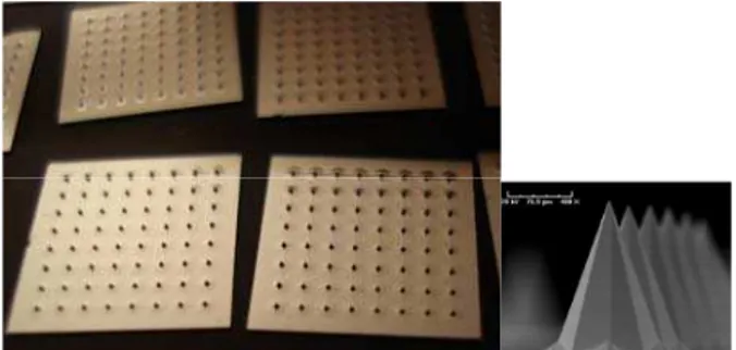
For both skin piercing and compressive failure tests we used arrays of silicon solid sharped microneedles, pyramidal in shape, with a base diameter of 250 micrometers, a tip radius of 5.5 micrometers and 308 micrometers high. Microneedles were arranged in squared matrices, with 64 needles per matrix, where the inter-axis distance between needles was 1 mm (Fig 1. and Fig 2.).
B. Skin piercing tests
To determine the force required by microneedles arrays to pierce the skin, we realized a test station similar to the one used by Davis [4], connecting a linear motorized slide (210 mm FS; EZ limo) with a load cell (3 kg FS; DS Europe) to a system for the skin electrical impedance measurements. Slide movements were controlled via PC, while the measured force and skin impedance data were collected and stored in PC memory (sampling frequency (sf) is 50 Hz for the force measurement system and 1 kHz for the impedance measurement system). Microneedles arrays, manually centred with respect to the load cell axis and in electrical contact with the impedance measurement system, were moved (velocity (v)=1 mm/s) by means of the slide towards a sample of excise human skin, pretensioned (ε=30%) through an uniaxial mechanical support to reproduce the physiological conditions, and electrically connected to the impedance measurement system thanks to a grip electrode (Fig.3).
Three array samples were tested. After the piercing experiments, they were observed at a stereomicroscope to detect any potentially failed needles.
Figures 1 – 2: Microneedles array samples photograph and a
magnification of a single microneedle with SEM.
Figure 3: Experimental set up used for realizing piercing tests.
C. Compressive failure tests
To determine the maximum force before failure of microneedles arrays under compression conditions we used an Enduratec station (16 mm FS; BOSE). We designed and manufactured an ad hoc a punch (Fig.4), able to distribute the force on the entire array surface, centered with respect to the load cell, and connected to the upper clamp of the Enduratec station. The compression tests were carried out under displacement-control through a PC (ramp rate=1µm/s; sf= 10 Hz).
Array samples with microneedles downwards were manually centred with respect to the punch and placed onto the slide connected to the load cell (Fig.5). Tests were stared after the contact between the punch and the sample was occurred, when 0.1 N of force were detected by the load cell.
Displacement and force measured data were collected by means of a PC for three array samples.
After this session of tests, arrays were observed through stereomicroscope and Scanning Electron Microscopy (SEM) to evaluate the failure of the microneedles, the number of microneedles failed, and their modality of failure.
Figure 4: Experimental set up used for realizing compressive tests.
Slide
Load cell
Impedance system
Skin
Uniaxial support
Array
Slide Punch Sample
Figure 5: An E-Pro drawing of the punch.
III. PRELIMINARY RESULTS AND DISCUSSION
In piercing tests, the behaviour of the skin impedance is opposite to that of signal force, as expected [4] (Fig.6): when the matrix of microneedles cames in contact with the excised skin, the force starts to increase, while the impedance reduces due to the growing of the contact surface of microneedles tips.
When the microneedles pierce the skin the impedance signal drops, because the disruption of the SC barrier permits a direct contact between whole microneedles and conductive epidermis layers, increasing the conductivity of the circuit. Force signal simultaneously decreases, after having reached a value of about 11 N, due to the relaxation of the failed tissue. Force signal then increases again because the slide continues its motion until stop, pushing the matrix of microneedles towards skin substrate.
In the last part of the curve, impedance signal does not vary because any change of the conductive contact surface happens.
Array samples were finally observed with stereomicroscope and they do not show any crack or failure sign. All the microneedles were covered by a slight film of organic material, due to the contact with human skin. Although we can not estimate the exact number of microneedles that effectively pierced skin, our data suggest that skin was pierced by a sufficient number of microneedles, able to induce a decrease of both force and impedance signals, as reported by Davis [4] -[5].
Figure 6: A representative result of a skin piercing test (sample 1):
the failure of skin due to piercing and to insertion of microneedles is observable as in the electric impedance signal (black) as in the force signal (green).
The displacement and force data obtained during the compressive tests for one of array samples is shown in Fig.7: both force and displacement, in a first fase, showed some ripples, probably due to the fracture of needles occurred when the contact between the punch and matrix was not homogeneously distributed on all the needles.
Hypothesizing a Young Modulus for {111} silicon of 186.5 GPa, and an ultimate stress of 7 GPa [9], we calculated for our needles, 308 micrometers tall, a displacement of failure of 11 micrometers, comparable with the minimum value of 10 micrometers in height for failed microneedles tips, observed through SEM images. According to this, we assumed a variation of 8 micrometers in displacement signal to identify needles failure events. Displacement ripples with variation of 8 micrometers correspond to ripples detected in the force data of 6 N in intensity.
After the initial stabilization fase, the force linearly increases until failure is achieved, at about 80 N, where all remaining needles fail: this event is also observable in a simultaneous variation of the displacement curve.
Not considering the number of needles fractured at the initial stabilization phase (13-26 microneedles), and taking in to account only the last pick force, we estimated that microneedles can withstand a force of about (1-1.6) N, comparable with literature results [4] - [5]. As a consequence, our matrix of microneedles could stand up to an estimated force of (64-102) N.
Figure 7: A representative result of a compressive test (sample 1):
the failure of the array is visible as in the force signal (blue) as in the displacement signal (pink).
Figure 8: Force vs Displacement in a compressive test (sample 3):
In addition, analysing force-displacement data (Fig. 8) we estimated the elastic constant for the entire array of microneedles and for the single needle, which were (1841-2257) N/mm for the array and (36.1-68.4) N/mm for the single needle, comparable with results reported in private communication [9].
Observing arrays with SEM and stereomicroscope, we observed that all the microneedles were failed but with different ways, probably due to the intrinsic variability of their crystal silicon structures. We identified 3 main failure modalities: M1, which corresponds to a global failure of the needle (Fig. 10 and Fig. 13), M2, which corresponds to a failure localized mainly at the top of the needle tip or at the lateral surface of the neelde (Fig. 11 and Fig. 14), M3, which corresponds to a limited fracture only at the top of the needle (Fig. 12 and Fig. 15). Failure modalities are present on array samples with the following percentages: M1: 12.5-32.1%; M2: 18.8-42.2 %; M3: 26.5-68.3%, and showed a homogeneous distribution on the entire array samples (Fig. 9), highlighting the reliability of the set up developed for the compressive mechanical tests.
Combining data from piercing and failure tests we can estimate a first margin of safety for an array of microneedles, obtaining a preliminary value ranging from 6 to 9: so, our microneedles arrays can withstand force required to pierce the human skin without breaking, being suitable for their use in real biomedical applications, as electrodes or components of transdermal drug devices.
1 2 3 4 5 6 7 8
1
2
3
4
5
6
7
8
Figure 9: Colour mapping representing the distribution of M1, M2,
and M3 failure modalities of a microneedles array (sample 3) after a compressive test: dark red is M1 failure modality; red is M2 failure modality; and light red is M3 failure modality.
Figures 10 – 11 – 12: Stereomicroscopy images of failed
microneedles according to M1, M2, and M3 failure modalities.
Figure 13: SEM image of failed microneedle according to M1 failure
modality.
Figure 14: SEM image of failed microneedle according to M2 failure
modality.
Figure 15: SEM image of failed microneedle according to M3 failure
modality.
IV. CONCLUSIONS
that our arrays of microneedles can withstand force required to pierce the human skin without breaking, having an estimated margin of safety of (6-9).
Next steps will concern an experimental campaign of compression failure tests and piercing tests of a major number of microneedles array samples, to validate the reproducibility of the proposed method. In addition, shear tests on microneedles arrays are planned in order to better characterize the behaviour of the matrix in use conditions. A specific experimental set up has to be designed and prepared at this purpose.
ACKNOWLEDGMENTS
Authors would thank Ing. F. Boschetti (Laboratory of Biological Structures, Politecnico di Milano) for her support in realizing compressive failure tests, and Ing. C. Casari and his group (Micro and Nanostructured Materials Laboratory, Politecnico di Milano) for the collaboration in the use of SEM.
REFERENCES
[1] P. Griss, H. K. Tolvanen-Laakso, P. Meriläinen,and G. Stemme, “ characterization of micromachined spiked biopotential electrodes”, IEEE Transactions on biomedical engineering, vol. 49(6), 2002, pp. 597-603.
[2] L.M. Yu, F.E.H. Tay, D.G. Guo, L. Xu and K.L. Yap, “A microfabricated electrode with hollow microneedles for ECG measurement”,Sensors and Actuators A: Physical, vol.151(1), 2009, pp. 17-22.
[3] D. W. Bodhale, a. Nisar, and N. Afzulpurkar, “Structural and microfluidic analysis of hollow side-open polymeric microneedles for transdermal drug delivery applications”,
Microfluid Nanofluid, Jul. 2009.
[4] S. P. Davis, B. J. Landis, Z. H. Adams, M. G. Allen and M. R. Prausnitz, “Insertion of microneedles into skin: measurement and prediction of insertion force and needle fracture force”,
Journal of Biomechanics , vol. 37, 2004, pp. 1155-1163. [5] S. P. Davis, M. G. Allen and M. R. Prausnitz, “The mechanics
of microneedles”, IEEE 2002 [Dig. 2nd Joint. EMBS/BMSE
Conf. USA, 2002, pp. 498-499].
[6] S. Chandrasekaran, and A. B. Frazier, “Characterization of surface micromachined hollow metallic microneedles”, IEEE,
2003, pp.363-364.
[7] J. H. Park, M. G. Allen, and M. R. Prausnitz, “Biodegradable polymer microneedles: fabrication, mechanics and transdermal drug delivery”, Journal of Controlled Release , vol. 104, 2005, pp. 51-66.
[8] J. W. Choi, I. B. Park, Y. M. Ha, M. G. Jung, S. D. Lee, and S. H. Lee, “Insertion force estimation of various microneedle array-type structures fabricated by a microstereolithography apparatus”, ICASE 2006 [Int. Joint. SICE-ICASE Conf. Korea, 2006, pp. 3678-3681].