J. Microw. Optoelectron. Electromagn. Appl. vol.12 número1
Texto
Imagem
Documentos relacionados
A tapped delay line is used to model the average power delay profile (PDP) in the distributed transmission cases and shows rather different features than the
It was due to a proper choice of the pump signal frequency regarding to the input signal that brings about a trade-off between four-wave mixing optical reshaping and
This work presents strategies for planning and performance evaluation through an empirical study of the QoS parameters of a voice over Internet Protocol (VoIP) application in
Abstract — We present a holey fiber (HF) with elliptical air-holes located in the center core area that ensures high birefringence, near-zero ultra-flattened
A novel 3 rd order WLAN U-band pass filter with two transmission zeros for sharp transition band using DGS, coupling matrix and multilayer technique has been
As shown in these figures the conventional (design A) ZOR is designed by using two coupling slots at the input and output ports, whereas proposed ZOR is designed
Abstract – This paper proposes an approach to estimate the probable location of maximum exposure to electromagnetic fields associated with a radiocommunication
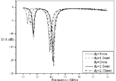
Here, the width of the ground plane of the proposed fractal monopole antenna is varied and its effect.. on the antenna bandwidth
