May 2017
Francisco Maria Cristão Marques Luquet Brasil
Bachelor of Science in Physics Engineering
Size-selected silver clusters on polymer surfaces as
plasmonic transducers for nano-biosensors
Dissertation to obtain the Master degree in Physics Engineering
Supervisor: Prof. Dr. Ana Gomes Silva, FCT-UNL
Jury:
President: Doctor Maria Isabel Simões Catarino
Arguer: Doctor Pedro Viana Baptista
iii
“Size-selected silver clusters on polymer surfaces as plasmonic transducers for nano-bio sensors.”
Copyright © Francisco Maria Cristão Marques Luquet Brasil, Faculdade de Ciências e Tec-nologia, Universidade Nova de Lisboa.
A Faculdade de Ciências e Tecnologia e a Universidade Nova de Lisboa têm o direito, perpétuo e sem limites geográficos, de arquivar e publicar esta dissertação através de exemplares impressos reproduzidos em papel ou de forma digital, ou por qualquer outro meio conhecido ou que venha a ser inventado, e de a divulgar através de repositórios científicos e de admitir a sua cópia e distribuição com objectivos educacionais ou de in-vestigação, não comerciais, desde que seja dado crédito ao autor e editor.
v "I don't know where I'm going from here,
but I promise it won't be boring.
vii
Acknowledgments
First and foremost, I would like to thank Professor Dr. Vladimir Popok for the op-portunity of integrating in his research project in Aalborg University and for his guidance and support throughout the development of this thesis. I would also like to thank Profes-sor Kjeld Pedersen for giving me the chance to research for my master thesis in the Aalborg University.
In addition, a thank you to Peter Fojan, Muhammad Hanif and Peter Jensen, who not only assisted me with some steps of the fabrication and characterization process, but also helped me to overcome all the hardships found during the experiments.
To Professor Dr. Ana G. Silva, I would like to express my sincere gratitude. Thank you very much for the opportunity to do this thesis, for all the encouragement and sup-port, for sharing all the knowledge in the long scientific discussions, the advices in all moments and the lovely week passed in Aalborg.
I would like to thank my friends for the support and motivation throughout my university years. To Pedro and Sofia who were with me since the beginning, to Flávia and Marta for the funny moments and support throughout these years (Pump the Jam!). To Mafalda and Lola, two stranger girls who shared a house with me in Aalborg, but since then they never left. And to Ricardo, the special guy who opened the door. Without them, these last years surely would not have been as fun as they were.
Finally, and most importantly, I would like to thank my family, my grandmothers Zica and Antónia, my uncle Miguel, my sister Carolina and specially my Mom and Dad. A big thank you for all the knowledge, encouragement, financial support, patience, laughs, and unconditional love that made all this possible.
ix
Abstract
The phenomenon of localized surface plasmon resonance (LSPR) was used for detection of proteins incubated on size-selected silver clusters embedded in poly (methyl methacrylate) (PMMA) layers. The silver clusters were produced by magnetron sputtering and subsequently size-selected by electrostatic quadrupole mass spectrometer (EQMS).
The size-selection process was followed by the deposition of silver clusters with low kinetic energies, i.e. in a soft-landing regime on PMMA, in order to avoid the deformation and/or frag-mentation of the silver clusters.
The role of PMMA hardness (viscosity) on cluster immersion was investigated to control the homogeneity in distribution of clusters, which can be partly or fully embedded in PMMA.
The viscosity of the polymers was found to be an essential part in the immersion of the silver nanoparticles into the polymer, which can be controlled through tuning of its viscosity or hardness utilizing simple thermal annealing of the samples.
The optical properties of the silver clusters - in particular the localized surface plasmon res-onance (LSPR) – were measured with the optical absorption spectra of the silver clusters, in which was possible to clearly identify an intensity and a resonance band of the deposited clusters.
Proteins of interest were incubated on the clusters utilizing antibody-antigen scheme and clear change in the parameters of the LSPR band was observed allowing protein detection and demonstrating applicability of the fabricated composites in bio-sensing.
xi
Resumo
O fenómeno de ressonância de plasmão localizado em superfície (LSPR) foi usado na detec-ção de proteínas em agregados de prata, de tamanho previamente selecionado e depositados em polimetilmetacrilato (PMMA).
Os agregados foram produzidos por pulverização catódica de magnetrão e subsequente-mente selecionados em tamanho por um espectrómetro de massa do tipo quadrupólo electroestá-tico, seguindo-se a sua deposição em PMMA em regime de baixas energias cinéticas (soft-landing), de forma a evitar a sua deformação e/ou fragmentação.
A dureza e a viscosidade do PMMA demonstraram ter um efeito relevante no controlo da imersão e homogeneidade dos agregados depositados, tendo por isso sido usados e testados dife-rentes tipos de PMMA.
As propriedades ópticas dos agregados – em particular a ressonância localizada do plasmão - foram obtidas medindo-se a sua absorção, tendo sido possível identificar claramente a intensidade e a banda de ressonância dos diversos agregados.
Como proteína de teste foi usada albumina de ovos de galinha. A ligação da proteína aos agregados é realizada utilizando a interacção química anticorpo-antigene. Foi comprovado com sucesso que a ressonância do plasmão se altera após ligação à proteína, demonstrando a sua apli-cabilidade como um transdutor para um nano biossensor.
xiii
Preface
The experimental work was carried out at the Department of Physics and Nanotech-nology at Aalborg University, Denmark, for seven months in the spring of 2015. The pur-pose of this research was to produce and deposit metal clusters of silver on a quartz sub-strate with a thin film of PMMA and to characterize the samples using optical spectros-copy and AFM. The final goal of this thesis is to use the metal clusters as transducers for bio-nanosensors. The thesis was carried out under the supervision of Professor Dr. Ana Cristina Silva, Professor at Faculdade de Ciências e Tecnologia, Universidade Nova de Lisboa.
xv
Contents
PREFACE ... XIII LIST OF FIGURES ... XVII LIST OF TABLES ... XXI INTRODUCTION ... 1 CLUSTERS AND CLUSTER-PMMA INTERACTION ... 3 THE SPHERICAL CLUSTER APPROXIMATION ... 4 FUNDAMENTAL ASPECTS OF CLUSTER NUCLEATION AND GROWTH ... 5 CLUSTERS PMMA INTERACTIONS ... 8 PLASMONIC SENSING ... 11 LOCALIZED SURFACE PLASMON RESONANCE ... 12 OPTICAL PROPERTIES OF NANOPARTICLES ... 14 LOCALIZED SURFACE PLASMON RESONANCE IN BIOSENSING ... 15 EXPERIMENTAL METHODS ... 17 CLUSTERS PRODUCTION ... 17 Magnetron Sputtering ... 18 Size-selection of clusters ... 20 NANO-BIOSENSORS SYNTHESIS ... 22 TOPOGRAPHIC AND OPTICAL TECHNIQUES ... 26 RESULTS AND DISCUSSION ... 28 AFM CHARACTERIZATION OF NANO-BIOSENSORS ... 28 PLASMON RESONANCE ANALYSIS OF NANO-BIOSENSORS ... 35 CONCLUSIONS AND FUTURE PERSPECTIVES ... 47 REFERENCES ... 49xvii
List of Figures
FIGURE 1 – SCHEMATIC OF THE SPUTTERING PROCESS OF SILVER NUCLEATION IN DIMERS. THE UNITS – CIRCLES – REPRESENT ATOMS AND IONS, WHILE DOTS REPRESENT ELECTRONS. THE SMALLEST CLUSTER IS THE SILVER (AG)
DIMER. ... 5
FIGURE 2 – SCHEMATIC OF THE DIFFERENT PROCESSES OF THE CLUSTERS GROWTH ON THE AGGREGATION ZONE OF THE CHAMBER, INCLUDING THE I) ATTACHMENT OF THE ATOMS, II) COAGULATION, III) COALESCENCE, AND IV) AGGREGATION OF THE SILVER CLUSTERS. ... 6
FIGURE 3 – SCHEMATIC OF THE TWO CLUSTER BEAMS KINETIC REGIMES, WITH (A) CLUSTER SOFT LANDING AND (B) CLUSTER-SURFACE HIGH-ENERGY IMPACT [29]. ... 8
FIGURE 4 – SCHEMATIC OF PLASMON OSCILLATION FOR A METAL NP, SHOWING THE DISPLACEMENT OF THE CONDUCTION ELECTRON CLOUD ABOUT THE CORE OR NUCLEI, DUE TO STRONG COUPLING WITH INCIDENT LIGHT [33]. ... 12
FIGURE 5 – SURFACE (I) AND LOCALIZED (II) SURFACE PLASMON RESONANCE PHENOMENA. ON THE RIGHT SIDE OF (I) AND ALSO IN (II) CAN BE SEEN THE EXPONENTIAL DECAY LENGTH OF THE EM FIELD FROM THE INTERFACE. ADAPTED FROM [13] ... 13 FIGURE 6 – DIAGRAM ILLUSTRATING HOW THE NANOSTRUCTURE SHAPE AFFECTS THE EXTINCTION WAVELENGTH MAXIMUM (𝝀𝒎𝒂𝒙 ) [38]. ... 15 FIGURE 7 – SCHEMATIC OF THE SYSTEM USED FOR THE PRODUCTION AND DEPOSITION OF SILVER CLUSTERS [39]. ... 18 FIGURE 8 – MAGNETRON HEAD WITH THE SILVER TARGET ALREADY ERODED BY THE SPUTTERING GAS (I)), COMPOSITION OF THE MAGNETRON SPUTTERING ON THE AGGREGATION CHAMBER, WITH THE COOLING SYSTEM AND THE GAS FLOW CIRCUIT (II)). ... 19
FIGURE 9 – NOZZLE-SKIMMER CONFIGURATION INSIDE THE SOURCE CHAMBER (I)), WHERE IS VISIBLE THE REFLECTION OF THE PLASMA FORMED IN THE AGGREGATION CHAMBER IN THE SKIMMER. THE SCHEMATIC REPRESENTATION OF THE PRODUCTION OF SILVER CLUSTERS IN (II) ... 19
FIGURE 10 – CROSS-SECTIONAL VIEW OF THE QMS WITH INCLUDED TRAJECTORIES FOR POSITIVE, NEGATIVE AND NEUTRAL CLUSTERS, RESPECTIVELY [27]. ... 20
FIGURE 11 – SCHEMATIC OF THE STEPS FOR THE PRODUCTION OF TRANSDUCERS FOR PROTEIN SENSING, ADAPTED FROM [41]. ... 24
FIGURE 12 – CHEMICAL FORMULA OF 11-MERCAPTOUNDECANOIC ACID (MUDA). ... 24
FIGURE 13 – CHEMICAL FORMULA OF EDC (I) AND NHS (II) ... 25
FIGURE 14 – SCHEMATIC OF THE ANTIBODY ANTIGEN BINDING [44]. ... 25
FIGURE 15 – A TOPOGRAPHIC AFM IMAGE OF A SAMPLE WITH SIZE-SELECTED CLUSTERS DEPOSITED ON A THIN PMMA FILM CAN BE SEEN IN I) AND THE ANALYSIS OF A CROSS SECTION OF A DEPOSITED CLUSTER SELECTED FROM I) UTILIZING THE SOFTWARE FROM NT-MDT IN II) ... 26
xviii
FIGURE 16 – SCHEMATIC REPRESENTING THE THREE STEPS OF THE PLASMON SENSING. I) PLASMON BAND FOR SIZE -SELECTED SILVER CLUSTERS DEPOSITED ON PMMA; II) PLASMON BAND FOR THE ANTIBODIES INCUBATED ON SILVER CLUSTERS; III) PLASMON BAND FOR THE ANTIGENS ATTACHED TO ANTIBODIES, ADAPTED FROM [45]. .. 27
FIGURE 17 – AFM IMAGE AND THE CORRESPONDING HEIGHT HISTOGRAM FOR CLUSTERS DEPOSITED ON A HARD (𝑻 =
𝟏𝟖𝟎℃) POLYMER OF 100 NM THICKNESS. ... 29
FIGURE 18 – AFM AND THE CORRESPONDING HEIGHT HISTOGRAM FOR CLUSTERS AS-DEPOSITED ON 100 NM VISCOUS POLYMER (SAMPLE # 16). ... 30 FIGURE 19 – AFM AND THE CORRESPONDING HEIGHT HISTOGRAM FOR CLUSTERS DEPOSITED ON 100 NM VISCOUS
POLYMER, ANNEALED AT 𝟗𝟓℃ FOR 10 MIN (SAMPLE # 16). ... 30
FIGURE 20 – AFM AND THE CORRESPONDING HISTOGRAM FOR CLUSTERS DEPOSITED ON 100 NM VISCOUS POLYMER, ANNEALED AT 𝟏𝟎𝟎℃ FOR 10 MIN (SAMPLE # 16). ... 30
FIGURE 21 – AFM IMAGE AND CORRESPONDING HEIGHT HISTOGRAM FOR THE CLUSTERS DEPOSITED ON SOFT
POLYMER, OF 20 NM THICKNESS ANNEALED TWO TIMES 𝟗𝟓℃; 30 MIN (SAMPLE # 18). ... 33 FIGURE 22 – AFM IMAGE AND CORRESPONDING HEIGHT HISTOGRAM FOR THE CLUSTERS DEPOSITED ON SOFT
POLYMER, OF 70 NM THICKNESS ANNEALED AT 𝟏𝟎𝟎℃; 30 MIN (SAMPLE # 18). ... 33
FIGURE 23 – AFM IMAGE AND CORRESPONDING HEIGHT HISTOGRAM FOR THE CLUSTERS DEPOSITED ON SOFT
POLYMER, OF 70 NM THICKNESS; ANNEALED AT 𝟏𝟏𝟓℃; 10 MIN (SAMPLE # 18). ... 33
FIGURE 24 – NORMALIZED ABSORPTION SPECTRA FOR SILVER CLUSTERS DEPOSITED ON HARD PMMA WITH
DIFFERENT THICKNESSES (54 NM PMMA BLACK LINE, 100 NM PMMA RED AND BLUE LINE). ... 35
FIGURE 25 – NORMALIZED OPTICAL ABSORPTION SPECTRA MEASURED FOR SILVER CLUSTERS DEPOSITED ON VISCOUS
PMMA WITH 100 NM THICKNESS (BLUE LINE), AND THEIR EVOLUTION WITH SUBSEQUENT ANNEALING AT
𝟗𝟓℃ (GREEN LINE) AND 𝟏𝟎𝟎℃ (RED LINE). ... 37 FIGURE 26 – NORMALIZED OPTICAL ABSORPTION SPECTRA MEASURED FOR SILVER CLUSTERS DEPOSITED ON VISCOUS
PMMA WITH 20 NM THICKNESS (BLUE LINE), AND THEIR EVOLUTION WITH SUBSEQUENT ANNEALING, TWO TIMES AT 𝟗𝟓℃ (GREEN LINE) AND ONE AT 𝟏𝟏𝟓℃ (RED LINE). ... 38
FIGURE 27 – NORMALIZED OPTICAL ABSORPTION SPECTRA MEASURED FOR SILVER CLUSTERS DEPOSITED ON SOFT
PMMA WITH 10 NM THICKNESS (BLUE LINE), AND THEIR EVOLUTION WITH SUBSEQUENT ANNEALING, TWO TIMES AT 𝟏𝟎𝟎℃ (GREEN LINE) AND ONE AT 𝟏𝟏𝟓℃ (RED LINE). ... 40
FIGURE 28 – NORMALIZED OPTICAL ABSORPTION SPECTRA MEASURED FOR SILVER CLUSTERS DEPOSITED ON SOFT
PMMA WITH 100 NM THICKNESS (BLUE LINE), AND THEIR EVOLUTION WITH SUBSEQUENT ANNEALING AT
𝟏𝟎𝟎℃ (RED LINE) AND 𝟏𝟏𝟓℃ (BLUE LINE). ... 41
FIGURE 29 – NORMALIZED OPTICAL ABSORPTION SPECTRA TO THE BACKGROUND (A)) AND TO THE MAXIMUM CONCENTRATION (B)), MEASURED FOR SILVER CLUSTERS DEPOSITED ON 100 NM VISCOUS PMMA, FOLLOWED BY STEPS FOR THE INCUBATION OF PROTEINS. ... 42
FIGURE 30 – NORMALIZED OPTICAL ABSORPTION SPECTRA TO THE BACKGROUND (A)) AND TO THE MAXIMUM CONCENTRATION (B)), MEASURED FOR SILVER CLUSTERS DEPOSITED ON 10 NM VISCOUS PMMA, FOLLOWED BY STEPS FOR THE INCUBATION OF PROTEINS. ... 43
FIGURE 31 – NORMALIZED OPTICAL ABSORPTION SPECTRA TO THE BACKGROUND (A)) AND TO THE MAXIMUM CONCENTRATION (B)), MEASURED FOR SILVER CLUSTERS DEPOSITED ON 20 NM SOFT PMMA, FOLLOWED BY STEPS FOR THE INCUBATION OF PROTEINS. ... 44
FIGURE 32 – NORMALIZED OPTICAL ABSORPTION SPECTRA TO THE BACKGROUND (A)) AND TO THE MAXIMUM CONCENTRATION (B)), MEASURED FOR SILVER CLUSTERS DEPOSITED ON 10 NM SOFT PMMA, FOLLOWED BY STEPS FOR THE INCUBATION OF PROTEINS. ... 45 FIGURE 33 – AFM IMAGE OF HARD SAMPLE # 9 CORRESPONDING TO THE SILVER CLUSTERS DEPOSITED ON HARD
xix FIGURE 34 – AFM IMAGE OF VISCOUS SAMPLE # 16 CORRESPONDING TO THE SILVER CLUSTERS DEPOSITED ON VISCOUS
PMMA I) AND AFTER THE ANTIGEN INCUBATION IN THIS SAMPLE II). ... 46
FIGURE 35 – AFM IMAGE OF SOFT SAMPLE # 18 CORRESPONDING TO THE SILVER CLUSTERS DEPOSITED ON SOFT
xxi
List of Tables
TABLE I – SIZE REGIMES FOR SILVER CLUSTERS ACCORDING WITH THE DEFINITIONS MADE BY JOHNSTON [19]. ... 3
TABLE II – CLUSTERS FLOW OF THE SPUTTER AND AGGREGATION GASES (AR AND HE RESPECTIVELY) DEPENDING ON THE CLUSTERS SIZE DESIRED. ... 21
TABLE III – PREPARATION CONDITIONS OF THE HARD, VISCOUS AND SOFT PMMA SAMPLES. ... 23
TABLE IV – MEAN VALUES OF CLUSTERS HEIGHT DEPOSITED ON HARD PMMA OF DIFFERENT THICKNESSES. ... 29
TABLE V – MEAN VALUES OF CLUSTERS HEIGHT DEPOSITED ON VISCOUS PMMA. ... 31
TABLE VI- MEAN VALUES OF HEIGHT, STANDARD ERRORS AND STANDARD DEVIATIONS, AND RELATIVE STANDARD DEVIATIONS FOR THE VISCOUS PMMA SAMPLES. ... 34
TABLE VII – WAVELENGTH OF LSPR MAXIMUM (𝝀𝒎) AND ABSORBANCE FOR SPECTRA IN FIGURE 24. ... 36
TABLE VIII – WAVELENGTH OF LSPR MAXIMUM (𝝀𝒎) AND BAND INTENSITY FOR SPECTRA IN FIGURE 25 AND 26. . 39
TABLE IX – WAVELENGTH OF LSPR MAXIMUM 𝝀𝒎 AND BAND INTENSITY FOR SPECTRA IN FIGURE 26 AND 27. ... 41
TABLE X – WAVELENGTH OF LSPR MAXIMUM 𝝀𝒎 AND BAND INTENSITY FOR SPECTRA IN FIGURE 29 AND 30. ... 44
xxiii
Glossary
AFM Atomic force microscopy
𝐸12 Kinetic energy per atom
𝐸345 Cohesive energy
𝐸678 Kinetic energy
𝑒 Charge of an electron
EQMS Electrostatic quadrupole mass spectrometer
LSPR Localized surface plasmon resonance
𝑚;<< Effective mass associated with the electrons move in response to the incident field
NHS N-Hydroxysuccinimide
NP Nanoparticle
𝑛 Density of electrons in the bulk
PMMA Poly (methyl methacrylate)
SCA Spherical cluster approximation
SPR Surface plasmon resonance
TEM Transmission electron microscopy
𝜀? Free space permittivity
𝜔A Plasma frequency
xxiv
𝛾EFFC Surface energy of PMMA
𝛾782;G<13; Surface energy in the interface of silver and PMMA
1
Introduction
Biosensors with noble metal nanoparticles have been intensively researched in the recent years, contributing to the expansion of the biosensors market which is expected to reach $22.68 billion by 2020 [1]. The interest for this technology resides in their many ad-vantages, in particular for optical biosensors due to their faster response, good selectivity, high sensitivity, low cost, and low interference with the phenomenon under study [2]. The technical advance of nano-biosensors in comparison with the traditional sensors has proven them to be an excellent tool with various applications in medical diagnosis, phar-maceutical and medical sciences [3,4], environmental monitoring [5], bio-recognition [6,7], bioprocessing and food quality control [8,9].
As generally defined, a biosensor is an analytical device with the ability to recognize the presence of a biological entity through a physical or chemical transducer and convert it into an output signal [10]. In 1960s, Clark and Lyons [11] proposed the idea of biosensors for the first time using an electrochemical sensor for glucose detection in blood plasma. This approach to the traditional mechanical sensors gave a new perspective for sensing biological materials.
According to the type of biological material , different techniques can be applied for its detection [12]. Amongst them, localized surface plasmon resonance (LSPR) biosensors have been an effective label-free tool for detection since the materials preserve their prop-erties once they are detected in their natural forms [13]. Usually, the size of nanoparticles in these LSPR based sensors is similar to that of the organic molecules targeted for detec-tion, such as enzymes and proteins, which makes them a good transducer for detection. Combining the nanostructure characteristics, the development of strategies for surface
2
bio-functionalization and the right bio-receptors to form nanostructure-biomolecules con-jugates, LSPR sensing can achieve unique photonic, electronic and catalytic properties for biosensing.
In contrast with the surface plasmon resonance (SPR) technique, the LSPR provides a higher degree of sensitivity of the material to be detected [14]. However, some concerns in the fabrication of stable transducers must be considered in order to have an accurate and reliable response. Some of the most challenging tasks in fabricating and forming a stable transducer are held by the detection scheme design and surface immobilization chemistry.
One of the most widely used processes to obtain NPs is their production from col-loids [15], even though this procedure results in particles with low stability and short shelf life times, leading to a rapid decay of their sensing properties. In this case, NPs are not usually size selected, i.e. there is a tendency to have particles of different sizes and many of them have the affinity to agglomerate with others. Another option to form NPs is through cluster beam systems [16,17]. In an earlier stage, this technique produces clusters in a gas phase, allowing for flexibility and precision in the control of the cluster beam composition and size. Afterwards, the clusters can be deposited on a substrate, which is carried out in high vacuum system. The versatility of this technique provides new appli-cation perspectives on nanostructuring of surfaces.
Real-time efficient detection of proteins of interest for several industries through the phenomena of localized surface plasmon resonance (LSPR) is optimized in the present work due to its novel immobilization studies and techniques for silver cluster deposition on polymer surfaces.
The novelty here lies on the deposition method, with the production of thin films of poly (methyl methacrylate) (PMMA) with good adhesion prospect of the nanoparticles (NPs). This procedure gave new perspectives for the NPs stability on samples, resulting in an advance in optical transducing technology, in contrast to the ones produced until now in colloids. Also, previous works on the formation of transducers for protein sensing using deposition of silver clusters on modified quartz surfaces were carried out [18].
3
Clusters and Cluster-PMMA
Interaction
Clusters are usually described as small aggregates of atoms or molecules that repre-sent a state of matter that is intermediate between atoms and the solid or liquid state, with properties that depend strongly on the size, shape, material of the particle, and its envi-ronment [19]. The unique physical, chemical and electronic properties of the NPs are a result of the high surface-to-volume ratio in clusters when compared to their bulk coun-terpart [16].
Regarding the nature of the clusters, they can be subdivided in terms of their con-stituent atoms (metallic, non-metallic or semiconducting) and the nature of the atomic bonding in those clusters. Silver nanoparticles are chosen as the clusters material in this work due to their high free carrier concentrations, which allows the formation of surface plasmons. Usually, the structure and the atomic arrangement of clusters are more complex and changeable than a solid bulk. By adding one or a few atoms, it is possible to change the entire cluster structure. Since the clusters size can differ depending on the parameters used in their production, they are divided in different categories according to their size boundaries (Table I).
Table I – Size regimes for silver clusters according with the definitions made by Johnston [19].
2
4
In Table I, 𝑁 represents the number of atoms in a cluster, 𝑁𝑆 the number of atoms at
the clusters surface and 𝐹𝐶 is the fraction of atoms at the surface regarding the total
num-ber of atoms. Also, in Table I, the clusters size regime is represented by a grey scale, which is usually not well defined due to the complexity of determining a defined boundary for the clusters size, often differing in the literature [19-21].
The spherical cluster approximation
Clusters theory is described by several theoretical models which differ essentially on their applicability according to the cluster size regime and the nature of the atoms forming the clusters. Regarding metal clusters, the spherical cluster approximation (SCA), [19], the liquid drop model (LDM) [22,23] and the Jellium model [24], are some of the models that provide reliable approaches to study the clusters properties, depending on their size, geometry and shape.
For the clusters produced in this work, the model of the spherical cluster approxi-mation (SCA) [19] is a good approach that considers a cluster sphere composed of 𝑁 at-oms, with cluster radius 𝑅3 and total volume 𝑉3.
The clusters volume is given by the volume of an atom multiplied by the number of atoms in the cluster, 𝑉3 = 𝑉1𝑁. N can be expressed in terms of the cluster and atomic radii,
where for a single atom the volume will be 𝑉1 and the radius 𝑅1.
𝑅3 = 𝑁QR 𝑅1 (2.1)
The cluster surface area 𝑆3 can be described as a function of the total number of
at-oms 𝑁 in the cluster. For a single atom, with a surface area of 4𝜋𝑟V, it yields:
𝑆3 = 4 𝜋𝑅3V = 4 𝜋 𝑁QR 𝑅1
V (2.2)
The number of atoms on the surface, 𝑁W, is determined by dividing the surface area
of the cluster by the cross section of an atom in the cluster, 𝜋𝑅1V:
𝑁W=4 𝜋𝑁 V R 𝑅1V 𝜋𝑅1V = 4 𝑁 V R (2.3)
The fraction of atoms on the surface of the cluster, 𝐹3, is simply related to the total
number of atoms in the clusters:
𝐹
3 =
𝑁W
5 The relation in equation (2.1) will be used in this work to calculate the number of atoms in the clusters. Considering the mean radius for size-selected silver clusters pro-duced, 𝑅3≈ 6.5 nm, with the Wigner-Seitz atomic radius of silver, 𝑅`a = 1.66 Å [25], the
number of atoms 𝑁 in the cluster using the SCA will be:
𝑁 = 𝑅3 𝑅`a
R
≈ 6.11 ×10f atoms, (2.5)
which will represent a fraction of atoms on the surface of the cluster of 𝐹k = 0.10, meaning
that the amount of the surface atoms is 𝑁a = 6160 atoms. Also, regarding Table I, the
clus-ters size regime where the produced silvers clusclus-ters are situated is between the large and the bulk regime.
Fundamental aspects of cluster nucleation and growth
The main aspects in the clusters formation are the nucleation (formation of a dimer as a nuclei) and the growth (larger than a dimer) processes [16]. The nucleation process is difficult to control and requires special conditions for the formation of clusters, since the experimental tools used are not capable of capturing, identifying and monitoring the nu-clei. The nucleation process can be understood in terms of the kinetics of the formation of the initial NPs followed by their interaction in vapour form [26].
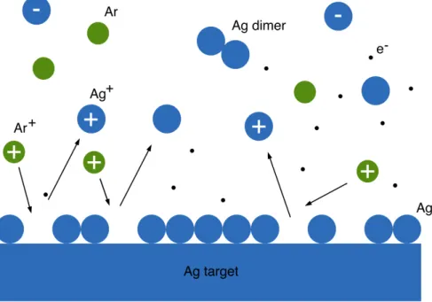
Figure 1 – Schematic of the sputtering process of silver nucleation in dimers. The units – circles – represent
6
In this work, silver atoms are obtained by sputtering a silver target with argon (Ar) ions, usually known as the sputtering gas (Figure 1). From the sputtering process, positive and negative silver ions can be obtained as well as neutral atoms. Usually, negative ions are obtained in a higher percentage [27]. The nucleation occurs when at least metal at-oms/ions collide with each other involving a third particle (Ar) to absorb the excess energy released at the nucleation. The chemical reaction and the three-body collision process can be represented as the following equation:
𝐴𝑔 + 𝐴𝑔 + 𝐴𝑟 à 𝐴𝑔V + 𝐴𝑟 (2.6)
After the nucleation (the smallest cluster/nuclei), clusters will enter in the aggrega-tion zone with specific experimental condiaggrega-tions such as temperature and pressure, leading to clusters with different sizes and thermodynamically stable.
For the growth of clusters, different independent processes can occur (Figure 2), in-cluding atom attachment, coagulation (kinetic and diffusion modes), coalescence and ag-gregation [21,26]. The size of clusters will depend on the time the clusters stay in aggrega-tion zone, where longer times lead to larger clusters. The size distribuaggrega-tion of the clusters is also dependent on the charge of the clusters and on the ratio of positive to negatively charged particles.
Figure 2 – Schematic of the different processes of the clusters growth on the aggregation zone of the
cham-ber, including the i) attachment of the atoms, ii) coagulation, iii) coalescence, and iv) aggregation of the sil-ver clusters.
7 During the attachment process (Figure 2 i)), silver single atoms/ions become at-tached to the clusters 𝐴𝑔8 (𝑛 ≥ 2) already formed [26]:
𝐴𝑔8 + 𝐴𝑔 → 𝐴𝑔8+ 1 (2.7)
This process can occur at any instant of time in the aggregation zone of the chamber. Some of the atoms attached to dimers and clusters formed by this process have less stabil-ity than the dimers formed during the nucleation process (Figure 1), due to the transfer of additional energy from the attachment to the buffer gas (Ar) [28].
The coagulation process is the formation of larger clusters from two individual clus-ters of smaller sizes (Figure 2 ii)). This process can happen in two different regimes, kinetic and diffusion regimes, which is directly dependent on the Brownian motion of the buffer gas in the aggregation zone, allowing the interaction between the atom and the cluster. In the kinetic regime, only single atoms or molecules can interact with the cluster, while in the diffusion regime many atoms interact simultaneously with the cluster.
Coalescence results from the interaction of clusters with a parent vapor and it only occurs for the very low degree of supersaturation. For smaller clusters, the rate of atom evaporation is higher than the rate of atom attachment, while for larger clusters the inverse relation is observed (Figure 2 iii)). As a result, large clusters grow while small clusters evaporate. Coalescence depends on the critical cluster size or radius for equilibrium with a parent gas or vapor.
Aggregation is a process where the individual clusters are joined due to their con-tacts while retaining much of their original shape [26]. This process results in the fractal growth of clusters (Figure 2 iv)).
8
Clusters PMMA interactions
In this section, it is presented an overview of the interaction process between silver clusters and a PMMA thin film deposited on quartz. Depending on the used type of cluster source, two different regimes for clusters deposition can be verified, depending on the kinetic energy of the generated cluster flow [29] (Figure 3).
Figure 3 – Schematic of the two cluster beams kinetic regimes, with (a) cluster soft landing and (b)
cluster-surface high-energy impact [29].
The surface properties of the Ag clusters, in particular those affecting the plasmon resonance, are very much dependent on their interaction with the PMMA surface and how they become, partly or fully, embedded into a surface, thus being of great importance a precise control during their deposition, the kinetic energy 𝐸678 of the clusters is then an
important parameter during the deposition, to establish the appropriate regime of the cluster-surface interaction, distinguished into low and high energy [29].
In the case of low-kinetic energy (Figure 3a), which is the impact regime considered in this work, the kinetic energy per atom (𝐸12) is lower than the cohesive (or binding)
energy (𝐸345) of the cluster constituents, which is typically around 𝐸12≈ 0.1 𝑒𝑉/𝑎𝑡𝑜𝑚 [29].
Moreover, in the soft-landing regime the cluster fragmentation is greatly reduced, preserving their decomposition, even though their structure/shape can be distorted due to the impact.
If 𝐸12 is close to 𝐸345, or if the atoms of the deposited cluster strongly interact with
the substrate atoms, the clusters can face a plastic deformation. Otherwise, if the 𝐸12
exceeds 𝐸345, the impact is of high-energy, and according to 𝐸12 and 𝐸678, the clusters can
9 The embedment of clusters, partly or fully, is dependent on the PMMA surface and cohesive energies of the constituents. By annealing the PMMA, the bulk structure and cohesive energy can change, offering more or less resistance to the penetration of the clusters. In this work, hard, viscous and soft PMMA, annealed at different temperatures, were used.
In order to achieve the complete embedding of a cluster into a polymer, the different energies involved should obey to the following relation [30]:
𝛾CD> 𝛾EFFC+ 𝛾782;G<13;, (2.8)
where 𝛾CD and 𝛾EFFC are the surface energies of the silver cluster (𝛾CD≈ 1200 mJ/mV) and
polymer (𝛾EFFC≈ 30 − 40 mJ/mV) [31], respectively, and 𝛾782;G<13; is the cluster-polymer
interfacial energy. This condition is usually satisfied for metal clusters on a polymer, since metals generally have surface energies two orders of magnitude higher than the polymers, and thus complete embedding is expected.
The embedding of a metal cluster depends also on the chain mobility changes of the polymer induced when clusters are deposited, which is only verified by tuning the viscos-ity/hardness of the polymer. Depending on the annealing temperatures of the PMMA, a total, partial or no embedding of the silver clusters can be expected.
For PMMA, it is expected that for temperatures above the glass transition tempera-ture, 𝑇D= 105℃ [31], silver clusters deposited in a soft-landing regime will stay at the
surface, since the kinetic energy of the silver clusters is lower than cohesive energy of the polymer.
The kinetic energy of each atom used in this work can be determined by the expres-sion:
𝐸CD=
𝑚CD 𝑣V
2 ,
(2.9)
where the atom mass of silver is 𝑚CD= 108×1.67×10YV~ Kg and 𝑣 is the velocity of the
silver NPs, 𝑣 ≈ 200 𝑚/𝑠. As such, the energy of a silver cluster can be of the order of:
𝐸CD= 3.6 × 10YVQJ =3.6 × 10YVQJ
𝑞 = 22.5 meV, resulting in a kinetic energy for each cluster of 𝐸k = 𝑁 𝐸CD ≅ 136 eV.
This kinetic energy will characterize the deposition regime, and the dependence for the clusters embedment will rely only on the thermal annealing of the PMMA, which will be discussed on Chapter 5.
11
Plasmonic Sensing
The moment where a beam of light traveling through a dielectric (air, water, glass) reaches a surface of a conducting material creates a traveling wave at the metal-dielectric interface, due to displacement of the electronic cloud [32]. This wave is commonly referred to as a surface plasmon, with a natural plasma frequency (𝜔A) at which the oscillation
occurs, that is defined as:
𝜔A = 𝑛𝑒V 𝜀?𝑚;<<
(3.1)
where 𝑛 is the density of electrons in the bulk, 𝑚;<< is the effective mass which is
associ-ated with the electrons move in response to the incident field, 𝑒 is the charge of an electron and 𝜀? is the free space permittivity.
The plasmon frequency is not a single resonant frequency associated with the elec-trons in the bulk of the metal. Instead, the motion will be based on whether the elecelec-trons can respond quickly enough to the driving force of the incident field. If the frequency of the incident field is different than 𝜔A, most of the incident light will be scattered.
However, if the incident field is equal to 𝜔A, i.e. the natural frequency of the
oscilla-tion, the incident light will be absorbed by the oscillaoscilla-tion, thereby enhancing its amplitude which results in the plasmon resonance of the bulk material, also known as surface plas-mon resonance (SPR).
To fulfill the resonant condition, SPR should respect the momentum conservation of the system. Due to the differences between the momentum of the incident light and the surface plasmon, the resonant condition can be achieved through adaptive optics to in-crease the momentum of light. These surface plasmon waves will be confined only to flat
12
surfaces and they can only be excited by using special geometries required for matching the wave vector, 𝑘WA when producing the plasmon wave. However, when using metal
nanoparticles, the plasmon oscillations will be localized, as it will be explained in the fol-lowing section.
Localized surface plasmon resonance
When a surface plasmon is confined to a particle with a size much smaller than the wavelength of the light emitted, the particle’s free electrons will have a collective oscilla-tion, resulting in the so called localized surface plasmon resonance (LSPR) presented in Figure 4 [32]. The electric field near the particles’ surface is greatly enhanced due to the formation of surface plasmons and the intensity will decay exponentially with the distance (evanescent waves).
Figure 4 – Schematic of plasmon oscillation for a metal NP, showing the displacement of the conduction
electron cloud about the core or nuclei, due to strong coupling with incident light [33].
This phenomenon occurs in noble metal NPs with dimensions (10-150 nm) much smaller than the wavelength of incident light (400-900 nm). These NPs have extraordinary optical properties that are not exhibited by any other class of material, being unique de-pending not only on the morphology of the NP but also on the environment it is subjected to. By changing the size, shape and material composition of the NP, the sensing capability of the LSPR can be tuned. Once these resonances are excited, absorption and scattering intensities can be up to forty times higher than identically sized particles that are not plas-monic.
13 As a result of the induced plasmons oscillating locally to the nanostructure (LSPR) rather than along the metal-dielectric interface (SPR), the decay length of the electromag-netic field (EM) observed in localized surface plasmons is in the order of 𝛿ˆaE‰~6 𝑛𝑚 [34]
(Figure 5 ii)), and by comparing to surface plasmons of 𝛿aEE~200 𝑛𝑚 [35] (Figure 5 i)), one
can say that LSPR frequency is highly sensitive to the refractive index of the environment, where a change in refractive index results in a shift in the resonant frequency. This shift is easily measurable, which allows the use of metal nanoparticles for sensing applications on the nanoscale. The shorter field decay length for LSPR provides a sensitivity increasing of the refractive index changes on the surface.
The complexity of LSPR technology resides in the surface of the chip since the in-strumentation used to read the signal is quite simple. In sharp contrast, the complexity of SPR resides in the precise setup of the instrumentation to launch a surface plasmon and read it accurately. In biosensing applications, the differences between SPR and LSPR be-come specifically notable, namely the sensing volume of their respective plasmons cap-tured by what is referred to as bulk effect (Figure 5).
Figure 5 – Surface (i) and localized (ii) surface plasmon resonance phenomena. On the right side of (i) and
also in (ii) can be seen the exponential decay length of the EM field from the interface. Adapted from [13]
Due to the much larger plasma field of SPR, even biomolecules that are not actually bond at the sensor surface can be detected, causing a bulk effect or false positive reading. Therefore, SPR has not been successfully applied in the diagnostic field, such as blood-based immunoassays, as the detection of low-level biomarkers requires signal amplifica-tion.
In contrast, LSPR can only sense the molecules bound at the surface of the biosensor, while the other ones are invisible and do not contribute to the signal. However, LSPR has a marginal bulk effect due to the small size of the localized plasma evanescent field.
14
Optical properties of nanoparticles
In 1908 Gustav Mie [36] obtained the exact solutions to Maxwell’s equations of the macroscopic electromagnetism which can be applied to describe LSPR. The solution for the electromagnetic scattering considers a nanosphere of radius 𝑅 embedded in a homo-geneous and isotropic medium illuminated by a plane wave.
The scattered field and the field inside the particle can be obtained from the incident field by applying the boundary conditions between the nanosphere and the medium at the surface of the nanosphere by considering a linear, isotropic and homogeneous me-dium and a polarized incident wave plane.
With Mie’s formulation, one of the simplest way to calculate the extinction coeffi-cient of a metal nanosphere in LSPR can be represented by 𝑄;J2, and dependent on the
dimension, shape, density and local environment of the nanostructure [37]:
𝑄;J2= 24 𝜋𝑅𝜀I;Œ R/V 𝜆 𝜀7I 𝜀G+ 2𝜀I;Œ V+ 𝜀 7I (3.2)
where 𝑅 is the radius of the nanosphere, 𝜀I;Œ is the relative dielectric constant of the
me-dium surrounding the nanosphere (the dielectric constant is assumed to be a positive, real integer and wavelength independent), 𝜆 is the wavelength of the absorbing radiation, 𝜀G
and 𝜀7I are the real and imaginary parts of the metal nanoparticle dielectric constant,
re-spectively [5].The extinction coefficient measures the rate of transmitted light via scatter-ing and absorption for a medium.
The equation (4.2) shows that the interaction between a metal nanoparticle and the incident light depends strongly on the dielectric properties of the metal nanoparticle (𝜀G
and 𝜀7I). If the denominator of the bracketed expression approaches zero, 𝑄;J2 will
be-come extremely large and at this frequency the optical absorption and scattering will also be exceedingly strong. For that, the 𝜀G must be close to 2𝜀I;Œ.
For the size-selected silver clusters produced with 𝑑 ≈ 13 𝑛𝑚, the optical extinction has a maximum at the plasmon resonance frequency, which occurs at 413 nm. Due to in-teractions between the incident photons and the conduction electrons band of a noble metal nanostructure, a collective oscillation of the electrons and subsequent absorption within the ultraviolet visible (UV-Vis) band is generated.
15
Localized surface plasmon resonance in biosensing
One of the main applications of LSPR in biosensing is the detection of small mole-cules. As bio receptors (e.g. enzymes, antigens and antibodies) have dimensions in the range of 2 − 20 𝑛𝑚, similar to those of nanostructures, the two can be considered structur-ally compatible. This dimensional compatibility means that highly miniaturized signal transducers can be achieved through the combination of nanostructure characteristics, a wide selection of available bio receptors and the rapid development of surface bio-func-tionalization strategies.
The first step when designing a LSPR biosensor is to choose the nanostructure-bio-molecule conjugates. As mentioned before, noble metal nanostructures have unique pho-tonic, electronic and catalytic properties. By functionalizing these nanostructures with bi-omolecules, such as proteins or DNA, novel substrates can be developed to be used in different biomedical applications, such as sensing, imaging, diagnosis and therapy.
LSPR has been experimentally shown to be highly sensitive to several structural fac-tors, such as dimension, shape and spacing, as these factors impose requirements in the fabrication of the sensor substrates for reliable and repeatable measurements. Figure 6 il-lustrates the effect that the nanostructure can have on the extinction wavelength maxi-mum (𝜆Ž•• ) for different shapes of a nanostructure.
Figure 6 – Diagram illustrating how the nanostructure shape affects the extinction wavelength maximum
(𝝀𝒎𝒂𝒙 ) [38].
LSPR spectroscopy offers sensing through transduction of refractive index changes in close proximity to the surface of the noble metal nanoparticle. Formation of adlayers (adsorbate layers that are chemically interacting with the subtract) and biorecognition
16
events on the surface cause quantifiable shifts in the LSPR extinction wavelength maxi-mum, 𝜆I1J, due to the dependence of the adlayer refractive index, 𝑛. The refractive index
is related to the dielectric constant by 𝑛 = 𝜀Q/V, as demonstrated by:
Δ𝜆Ž••= 𝑚Δ𝑛 1 − exp −2𝑑
𝑙Œ (3.3)
where 𝑚 is the bulk refractive index response of the nanostructure, 𝑑 is the effective ad-sorbate layer thickness and 𝑙Œ is the characteristic electromagnetic field decay length,
mod-elled as an exponential decay [35]. The binding kinetics can then be monitored by tracking ΔλŽ•• as a function of either time or analyte concentration [37].
17
Experimental Methods
This chapter describes the experimental procedure followed in this work, where the process to form the silver clusters is explained, as well as all the steps to obtain the na-nosensors.
Clusters Production
Regarding the production of clusters, there are several techniques and procedures that can be applied. They depend on the experimental setup used in the cluster apparatus, which is usually composed by a production, a mass selection (if required) and a detection section.
Some fundamental requirements regarding the cluster material, size and energy dis-tribution, overall cluster electrical charge, must be taken into consideration during the de-sign of the experimental setup. In a first approach, it is necessary to choose an efficient clusters’ source with the required parameters to produce the desired clusters.
There are a vast number of sources used in the production of clusters, such as the supersonic nozzle (free jet), gas aggregation, surface erosion, thermospray, and elec-trospray sources [16]. In this work, a magnetron sputtering source is used to produce the size-selected silver clusters. This technique provides several advantages during the pro-duction and deposition steps, such as precise control of the composition and size of the clusters produced, the surface coverage, and the kinetic energy, which defines the cluster surface interaction.
18
Magnetron Sputtering
The magnetron sputtering cluster apparatus (MaSCA), presented in Figure 7, was used in the production and deposition of the silver clusters. The system consists of several vacuum chambers that can be defined by two different regions.
The red region presented in Figure 7 contains the magnetron where the material target is placed. In this region, a silver target is sputtered with a subsequent aggregation of this material into clusters. The left region of this chamber includes the ion optics cham-ber, where the beam of silver clusters will be collimated and then selected in size by the electrostatic quadrupole mass selector (EQMS), leading to their deposition on a sample.
Figure 7 – Schematic of the system used for the production and deposition of silver clusters [39].
The key part of a MaSCA system is the commercial source (NC200U from Oxford Applied Research) composed by a DC magnetron that allows the sputtering of a metal target by the Ar plasma. A silver target of 99.99% purity (from Good Fellow Ltd) is used to produce the silver clusters. The magnetron sputtering source is connected to the source chamber by the manipulator, allowing a 3D alignment of the source.
The linear translation in the range of 𝑙 ≈5-100 mm is very important here since it allows to vary the aggregation lengths that in turn affects the size of the formed clusters as well as the cluster beam intensity. For short aggregation lengths, the clusters produced will be smaller due to the fewer number of collisions, meaning that, the aggregation length must be increased to obtain larger clusters.
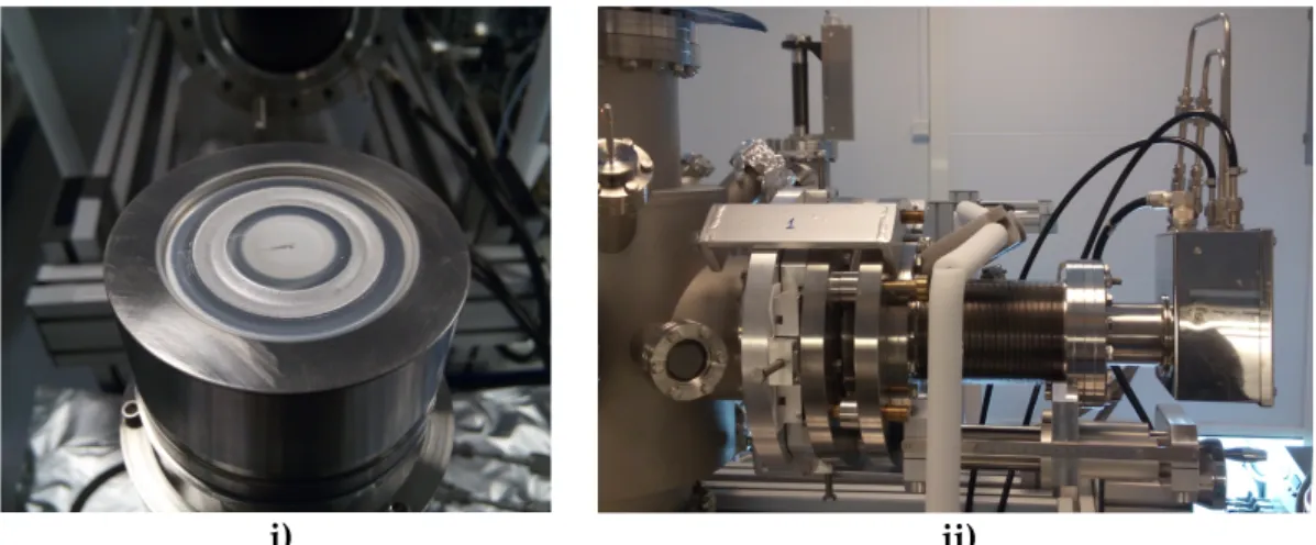
Figure 8 shows the magnetron sputtering system, with a detail of the magnetron head (Figure 8 i)), where it can be seen the silver target already eroded by the sputtering
19 gas (Ar). Also, in Figure 8 ii) the linear translation is visible below the magnetron, as well as the gas flow system (sputter and aggregation gases) and the cooling system.
Figure 8 – Magnetron head with the silver target already eroded by the sputtering gas (i)), composition of
the magnetron sputtering on the aggregation chamber, with the cooling system and the gas flow circuit (ii)). Using Ar and He (regulated by two gas flow controllers) as the sputter and aggre-gation gases, respectively, the silver target is sputtered and the clusters are aggregated. By varying the discharge power, the flows of sputtering and aggregation gases, and the ag-gregation length in the source, one can adjust the clusters size and the beam intensity.
The differences between the pressure in the aggregation and source chamber gener-ates an expansion through a nozzle into the source chamber creating a flow of charged silver clusters. The diameter of the nozzle is another important parameter to optimize the expansion process, which can vary from 1 to 5 mm (Figure 9).
Figure 9 – Nozzle-skimmer configuration inside the source chamber (i)), where is visible the reflection of the
plasma formed in the aggregation chamber in the skimmer. The schematic representation of the production of silver clusters in (ii)
20
Inside the source chamber (pumped by a 1250 l/s turbomolecular pump), a skim-mer is mounted at the entrance to the ion optics chamber with a 2 mm orifice which allows a collimated beam. The ion optics chamber (pumped by a 355 l/s turbomolecular pump) contains an Einzel lens and two pairs of deflectors to adjust the beam direction.
The pressure in the ion optics chamber is reduced about two orders of magnitude when compared to the source chamber, reaching typically 10−4-10-5 mbar. Between the
EQMS and the ion optics, a gate valve is mounted that allows to isolate EQMS and depo-sition chamber from the source. The parameters are optimized to direct the beam into the entrance orifice of the EQMS, allowing the size-selection of the clusters, which will be de-scribed in the following section.
Size-selection of clusters
One of the main concerns inherent to the clusters production is the size distribution, therefore it is imperative to have it into account for a practical application. The clusters expanded from the nozzle are assumed to have nearly the same velocity. A significant fraction of the produced clusters is ionized. Therefore, to achieve mass filtering, EQMS is used.
The EQMS is composed by electrodes of 120-mm-long quarter cylinders and are di-vided into two pairs that are biased with the same absolute voltages, 𝑈—E, up to 5 kV but
with opposite polarity. The electrodes are surrounded by a grounded shield with circular orifices for the cluster beam, where the orifices are covered by metal grids to minimize field penetration. Detailed description of the principle of operation of EQMS can be found elsewhere [27]. In brief, the EQMS consists of four electrodes (represented by red and yel-low in Figure 10) that create an electrostatic field.
Figure 10 – Cross-sectional view of the QMS with included trajectories for positive, negative and neutral
21 By varying the applied potential, it is possible to change electrostatic energy to make it match the kinetic energy of the clusters with a given mass. Thus, only clusters with this mass will be deflected 90o to enter the deposition chamber (Figure 10). For the
EQMS used, the diameter of the clusters can be selected with ± 5-7% precision. It has been proved clusters can be produced (but not limited) with diameters between ca. 5-25 nm [40].
One of the requirements for the setup is the ability to deposit clusters under high vacuum conditions, therefore, the deposition chamber is equipped with a 230 l/s turbo-molecular pump that allows for a background pressure of » 10-8 mbar. Two faraday cups
are used for beam monitoring: one in the main axis direction of the cluster source to meas-ure the clusters current produced by the MaSCA, and another one in the deposition cham-ber to measure the current of the size-selected clusters deflected by the EQMS and in-tended for the deposition on a substrate.
The parameters for cluster production presented in Table II were interrelated by many parameters which are typically varied for optimizing the beam intensity to obtain the desired cluster size.
Table II – Clusters flow of the sputter and aggregation gases (Ar and He respectively) depending on the
clusters size desired.
Clusters Size 𝑭𝑨𝒓 (sccm) 𝑭𝑯𝒆 (sccm)
Small 40 - 60 10 - 20
Large 50 - 65 2 - 10
The beam intensity, which depends on the kinetic energy of the NPs, also affect the sputtering power and gases used in the clusters formation. An additional parameter that affects the cluster’s size is the distance between the target and the nozzle (aggregation length, Figure 9 ii)), where a shorter aggregation length leads to smaller clusters due to the reduced number of collisions.
22
Nano-biosensors Synthesis
Before the deposition of size-selected clusters on substrates, a thin film layer of PMMA were deposited on silicon (Si) and quartz substrates by a standard spin coating equipment (model WS-650-23B from Laurell Technologies Corporation) from 1% solution of PMMA (molecular weight 950K PMMA C 9, MicroChem, America) diluted in toluene. The thin films were produced at the exactly same conditions for both types of sub-strates in order to measure the PMMA thickness on Si by ellipsometry and use this value as a reference for the PMMA thickness on quartz substrates.
In the current experiments, PMMA thickness varied between 10-100 nm depending on the parameters used on the spin coater (time, rotations per minute, and acceleration). Silver clusters of a given size (ca. 13 nm in diameter) were deposited on PMMA of different hardness and subjected to post-deposition thermal annealing to study immersion of par-ticles into the polymer.
Three types of PMMA films were prepared on quartz according to their annealing temperatures:
(i) Hard PMMA was annealed at temperatures quite above the glass transition prior the cluster deposition;
(ii) Viscous PMMA was only dried at ambient conditions prior the cluster deposition, thus, having low hardness that facilitates the cluster im-mersion;
(iii) Soft PMMA was annealed at temperatures below the glass transition (100℃) prior the cluster deposition.
These samples were tested as optical transducers to study the possibility of protein detection. Table III shows the preparation conditions of the PMMA thin films used for the deposition of the size-selected silver clusters.
23
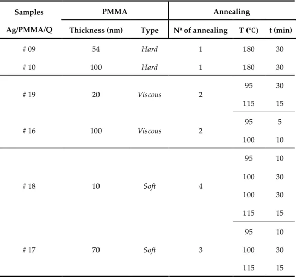
Table III – Preparation conditions of the hard, viscous and soft PMMA samples.
Samples Ag/PMMA/Q
PMMA Annealing
Thickness (nm) Type Nº of annealing T (℃) t (min)
# 09 54 Hard 1 180 30 # 10 100 Hard 1 180 30 # 19 20 Viscous 2 95 30 115 15 # 16 100 Viscous 2 95 5 100 10 # 18 10 Soft 4 95 10 100 30 100 30 115 15 # 17 70 Soft 3 95 10 100 30 115 15
After the initial characterization by AFM and optical spectroscopy, the samples which were qualified for protein sensing (i.e. with a high clusters density immobilized in the PMMA layer, giving a typical plasmon resonance peak for silver clusters) will be sub-mitted to all the steps in the building of a functional transducer for nano-biosensing, i.e. the functionalization of the samples surface through MUDA and their activation (EDC/NHS) for the deposition of proteins of interest (antibody, antigen). Table III shows all the selected samples that meet the requirements for protein sensing.
A schematic of the experimental procedure to obtain stable transducers for protein sensing is presented in Figure 11. The production of size-selected silver clusters is followed by their deposition in a quartz substrate with a thin film of PMMA on top.
24
Figure 11 – Schematic of the steps for the production of transducers for protein sensing, adapted from [41].
In order to have a stable and strong binding of the biomolecules to the NPs, a functionazilation of the clusters surface must be carried out. For that, substrates with as-deposited clusters were incubated in a solution of 10mM 11-Mercaptoundecanoic acid (MUDA) with 98% purity (from Sigma-Aldrich) diluted in 96% of ehtanol for 30 min, resulting in a formation of a self assemble monolayer (SAM) on the samples (Figure 11 ii)). Subsquently, the samples were washed with ethanol to remove the residual and not reacted MUDA and dried under a stream of nitrogen.
MUDA (Figure 12) becomes selectively bond to silver clusters via the sulphur-con-taining end (HS) and its carboxyl group (COOH) provides a covalent amid bond to the antibodies that will be deposited in the transducer.
Figure 12 – Chemical formula of 11-Mercaptoundecanoic acid (MUDA).
However, to form a bond between the functionalized NPs with MUDA and with the antibodies, a carboxyl activator agent should be present to bind the biomolecules to the NPs. For that, the samples were incubated with a freshly prepared solution of 40mg/mL 1-ethyl-3-[3-dimethylaminopropyl]carbodiimide hydrochloride (EDC) (Figure 13 i)) and
25 10 mg/mL N-Hydroxysuccinimide (NHS) (Figure 13 ii)) in 1 mL of deionised water for 20 min. Subsequently the sample was washed with deionised water and dried under a stream of nitrogen.
Figure 13 – Chemical formula of EDC (i) and NHS (ii)
EDC/NHS coupling will activate the carboxyl group (COOH) in MUDA, which will be used to form a covalent amide bond to the antibody [42]. The strong chemical bond will change the dipole characteristics of the silver clusters which will enhance the LSPR ab-sorption. This process in represented in Figure 11 ii) and iii)). The EDC coupling reaction should be carried out fast for an efficient bonding between MUDA and the antibody, as the reactive ester (an acid that replaces hydroxyl group (-OH) by an alkyl (-O) group) that is formed can be hydrolysed in aqueous solutions [43]. NHS will be the agent that will give stability to this active ester from the EDC coupling.
Regarding the detection of biological material of interest with the LSPR phenomena, an antibody-antigen scheme was used to test the transducers produced. The detection consists of an anti-chicken egg albumin (antibody) and albumin chicken egg white (anti-gen), a schematic of the antibody-antigen binding is shown in Figure 14. These proteins are well characterized and understood in the literature and they only have the purpose to test the applicability of the developing detection approach for this work.
Figure 14 – Schematic of the antibody antigen binding [44].
For the protein deposition, a 10 mM solution of chicken egg albumin (antibody) (from Sigma-Aldrich) in 20-30 µL of deionised water was incubated on the samples for 30
ii) i)
26
min (Figure 11 iv)). The samples were then washed with deionised water and dried under a stream of nitrogen followed by the measurement of the optical spectra. After the anti-body incubation, albumin chicken egg white (antigen) (from Sigma-Aldrich) in 1 ML of deionised water was incubated for 30 min (Figure 11 v)). The samples were then washed with deionised water and dried under a stream of nitrogen.
Topographic and optical techniques
An Atomic Force Microscope (AFM) and an optical spectrometer were used to char-acterize the samples produced in the MaSCA system. The main purpose of the AFM was to get a topographic imaging of the sample to analyse the distribution and the density of clusters on the surface. The AFM Ntegra Aura (from NT-MDT) was used in a semi-contact mode using standard commercial silicon cantilevers with curvature radius of tip better than 10 nm.
To analyze the topographic images collected, the software Image Analysis 2.1.2 (from NT –MDT) was used to determine the height of the deposited clusters. Figure 15 shows an example of an AFM image collected and a cross section of a deposited cluster.
Figure 15 – A topographic AFM image of a sample with size-selected clusters deposited on a thin PMMA
film can be seen in i) and the analysis of a cross section of a deposited cluster selected from i) utilizing the software from NT-MDT in ii)
Optical spectroscopy measurements were performed by double beam Perkin Elmer High Performance Lambda 1050 Spectrometer in a standard configuration in the UV-Vis-ible region of the spectrum (300-750 nm). The optical spectra were collected in transmis-sion mode.
27 The plasmon resonance characterization of the protein deposition first requires the optical characterization of the plasmon resonance of the bare silver nanoparticles depos-ited in PMMA. To check the quality and sensitivity of the transducers produced, the plas-mon peak position and absorbance intensity were measured, which are sensitive to the clusters density, shape and size (Figure 16).
Figure 16 – Schematic representing the three steps of the plasmon sensing. i) plasmon band for size-selected
silver clusters deposited on PMMA; ii) plasmon band for the antibodies incubated on silver clusters; iii) plas-mon band for the antigens attached to antibodies, adapted from [45].
The plasmon resonance of bare silver clusters (Figure 16 i)) will be the reference for the proteins that will be deposited and the sensing will be measured by the shifts of the 𝜆I1J observed on the spectra. The plasmon resonance peak position is then obtained by measuring the transmittance of the samples, which fulfils the conditions mentioned above. The measured transmittance spectrum is converted into absorbance using the relation:
𝐴 = 2 − log(𝑇 %) (4.1)
As previously mentioned on the clusters PMMA interaction section, metal clusters are deposited on PMMA with different hardness (hard, soft, and viscous) with the same param-eters of production and deposition presented on Table II. The samples will be character-ized regarding the size of the clusters and their optical properties, which are dependent on the way the clusters are deposited in PMMA with different types of annealing. In all experiments, a constant voltage of ±300 𝑉 was applied to the EQMS.
28
Results and Discussion
The discussion of the results obtained for the size-selected silver clusters deposited on PMMA thin films is divided into the AFM characterization of the topographic images and optical spectroscopy results for the absorption spectra of the samples for protein sens-ing.
AFM characterization of nano-biosensors
In this work, topographic AFM measurements were carried out for all the samples produced to first characterize the heights of the size-selected silver clusters deposited on PMMA layers. However, due to the different viscosities of the polymer and the embed-ment of silver clusters into them, the relative height measured will not be corresponded to the actual clusters size, i.e. the characterization will be focused only in the embedment process in viscous and soft PMMA layers.
Through AFM measurements, subsequently confirmed with transmission electron microscopy (TEM) measurements [46], it was found that the clusters preserve almost spherical shape after the deposition becoming just slightly oblate [40]. Thus, it is safe to assume that the clusters height measured on AFM topographic images is almost equal to their diameter and the term size is synonym for the height and diameter.
Also, it should be mentioned that specific regions of AFM images were considered for statistical analysis, with the more homogeneous coverage and with less clusters aggre-gation as possible. In Figure 17, a specific region of an AFM image and corresponding histogram for clusters deposited on hard polymer is shown.
29
Figure 17 – AFM image and the corresponding height histogram for clusters deposited on a hard (𝑻 = 𝟏𝟖𝟎℃)
polymer of 100 nm thickness.
From the topographic AFM image, a considerable number of nanoparticles is ana-lysed to have a good statistic of the number of clusters, in order to determine the mean silver clusters height. It should be mentioned that hard PMMA means that the polymer was annealed at temperatures above the glass transition, 𝑇 = 180 ℃.
Clusters deposited on hard PMMA samples confirm the success of their size-selec-tion through the height histograms (Figure 17), and for this type of PMMA hardness one can say that silver clusters do not embed deeper on polymer layers, staying only at the surface. Table IV lists all the results obtained for hard polymers with different thicknesses.
Table IV – Mean values of clusters height deposited on hard PMMA of different thicknesses.
Sample Ag/PMMA/Q (𝐏𝐌𝐌𝐀: 𝐓 = 𝟏𝟖𝟎 ℃) Thickness [nm] Mean Height [nm] Standard Error Height [nm] Standard Deviation [nm] Relative Standard Deviation [%] Number of Clusters # 12 35 12.15 0.06 (0.5%) 1.44 12 175 # 09 54 12.02 0.09 (0.7%) 1.65 14 140 # 10 100 12.10 0.09 (0.7%) 3.06 25 134
The mean height, <h>, averaged over 130 clusters on hard PMMA of different thick-nesses, from the Gaussian function is (12.09 ± 0.07) nm, which is slightly smaller than the mean height for clusters deposited on silicon (12.8 ± 1.5) nm [47], averaged over 500 clus-ters. One possible reason for this difference might be the low density/counts of clusters on hard PMMA samples.
30
Figure 18 – AFM and the corresponding height histogram for clusters as-deposited on 100 nm viscous
poly-mer (sample # 16).
Figure 19 – AFM and the corresponding height histogram for clusters deposited on 100 nm viscous polymer,
annealed at 𝟗𝟓℃ for 10 min (sample # 16).
Figure 20 – AFM and the corresponding histogram for clusters deposited on 100 nm viscous polymer,
31 Regarding the clusters deposited on viscous PMMA having different hardnesses, three AFM images, from PMMA with thickness of 100 nm (sample # 16) were analysed (Figure 18, 19, and 20).
Different hardnesses were achieved by heating the PMMA layers at different temper-atures after the deposition of clusters (as deposited, 95 ℃ and 100℃), (Table V). Among these three viscous PMMA layer, the hardest layer is the one heated at 100 ℃. For the clus-ters deposited on PMMA 10 nm thick, no AFM images are shown. In this case, it was not possible to get the heights due to the high density of clusters which results in their ag-glomeration.
AFM images collected for these samples with as-deposited clusters show that the mean height of clusters has decreased to around 8 nm with a wide size distribution and a long tail towards smaller particle heights. It can be suggested that the deposited clusters are partly immerse into the polymer due to its low hardness and high viscosity [46].
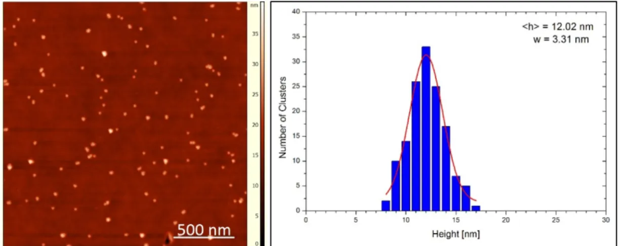
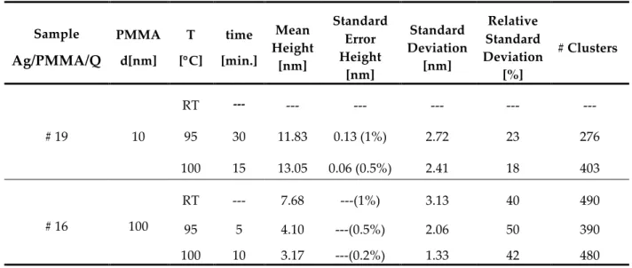
Table V – Mean values of clusters height deposited on viscous PMMA.
Sample Ag/PMMA/Q PMMA d[nm] T [°C] time [min.] Mean Height [nm] Standard Error Height [nm] Standard Deviation [nm] Relative Standard Deviation [%] # Clusters # 19 10 RT --- --- --- --- --- --- 95 30 11.83 0.13 (1%) 2.72 23 276 100 15 13.05 0.06 (0.5%) 2.41 18 403 # 16 100 RT --- 7.68 ---(1%) 3.13 40 490 95 5 4.10 ---(0.5%) 2.06 50 390 100 10 3.17 ---(0.2%) 1.33 42 480
The next step was to anneal the samples to investigate the immersion of the silver clusters deposited on the PMMA layer. This was performed in two steps, the first one at 95 °C and the second one at 100 °C, both for 10 min. The corresponding AFM images and histograms are shown in Figures 19 and 20.
It is clear that after the first annealing the cluster surface coverage decreases signifi-cantly and the <h> becomes much smaller, <h>= 4.10 nm. This effect occurs in the other viscous samples prepared at the same conditions but with different PMMA thicknesses. It was also verified that for thicker samples (100 nm), the embedment occurs deeper than in
32
thinner samples (10 nm). One possible explanation resides on the large amount of PMMA which is not cured. Therefore, during the annealing, the surface energy at the interface of NPs and PMMA would be the driving force for the immersion under higher temperatures. The second annealing, at 𝑇 = 100℃, also decreased the surface coverage and height for <h> = 3.17 nm. It seems that PMMA under thermal annealing is forcing the NPs to penetrate deeper into the film becoming fully embedded after some time.
Throughout the successive samples’ annealing, it can be verified that the clusters density at the PMMA surface increases and their agglomeration tend to disappear, prob-ably due to the differences between the surface energy of the silver clusters and PMMA [31]. This effect was also observed in the other samples produced with different thick-nesses.
Regarding soft PMMA samples, a similar process was followed for the samples’ an-nealing, with the difference that, before the deposition of silver clusters, the samples were annealed at a temperature below the glass transition, 𝑇 = 95℃.
An AFM image and corresponding height histogram are presented in Figure 21 for 20 nm thick soft PMMA. The clusters height in this case is close to the one expected from the previous experiments, around <h> » 13 nm.
This means that the silver clusters stay on the PMMA surface and do not immerse due to the hardness increased by the annealing of the PMMA. Another feature presented on the AFM image is the high density of NPs in the sample, denoting the different layers of NPs deposited possibly due to the surface roughness of the PMMA. For soft PMMA samples, the annealing temperature (below the glass transition temperature) has proven not to be sufficient to initiate the clusters immersion.
For a better understanding of the evolution of the clusters density on the PMMA, the sample was annealed after the cluster deposition in two steps: first at 95 °C for 10 min and then at 100 °C for 10 min. In comparison with the viscous polymers, the annealing did not produce any considerable change in the height distribution and in the cluster cover-age, indicating that temperatures below the glass transition are not sufficient to initiate the immersion of NPs.

![Figure 7 – Schematic of the system used for the production and deposition of silver clusters [39]](https://thumb-eu.123doks.com/thumbv2/123dok_br/15761043.1074831/42.892.116.753.393.719/figure-schematic-used-production-deposition-silver-clusters.webp)
![Figure 11 – Schematic of the steps for the production of transducers for protein sensing, adapted from [41]](https://thumb-eu.123doks.com/thumbv2/123dok_br/15761043.1074831/48.892.142.744.136.497/figure-schematic-steps-production-transducers-protein-sensing-adapted.webp)