A Numerical Study on the Stress Changes in the
Ballast due to Train Passages
José N. Varandas
1*, André Paixão
2, Eduardo Fortunato
2and Paul Hölscher
3 1CEris, ICIST, Department of Civil Engineering, Nova University of Lisbon, Portugal2
National Laboratory for Civil Engineering (LNEC), Portugal 3Geo-Engineering, Deltares, Delft, The Netherlands
[email protected], [email protected], [email protected], [email protected]
Abstract
The long-term settlement of railway tracks is a consequence of permanent deformations taking place in the track granular layers and subgrade. In the ballast layer, which experiences the highest stress amplitudes during train passages, these permanent deformations strongly depend on the loading conditions, which in turn depend on several factors as the train speed and axle loads, sleeper-ballast initial pressure, or track geometry quality. Moreover, under the action of moving loads from trains, further to a very significant increase of the vertical stress, the ballast layer experiences the rotation of the principal stresses, which is another aspect that significantly influences the long-term structural behaviour. This paper numerically analyses the stress changes in the ballast due to train passages, aiming at showing how these stresses may vary depending on the loading conditions. A numerical program of dynamic simulation is used that considers the nonlinear resilient nature of the ballast and the three-dimensional representation of the track-ballast-soil system using the FEM. The paper shows that dynamic effects due to trains travelling at very high speeds can significantly influence the stress path followed during loading and the principal stresses rotation inside the upper layers of the track. The paper also shows the importance of the consideration of the ballast nonlinear behaviour in the rotation of the principal stresses.
Keywords: railways, FEM modelling, nonlinear behaviour, ballast, stresses, principal stress rotation, high-speed
1
Introduction
Normally, the main contribution for the permanent settlement of railway tracks comes from the ballast layer (Selig & Waters, 1994). It experiences more and larger stress cycles due to train passages (Powrie et al., 2007) and is periodically tamped during maintenance operations. The loading conditions play a decisive role in the process, either in terms of the train speed, the train loads, or the
* Corresponding author
Volume 143, 2016, Pages 1169–1176
Advances in Transportation Geotechnics 3 . The 3rd International Conference on Transportation Geotechnics
(ICTG 2016)
dynamic component due to uneven railhead profiles. As the train passes, combined with a significant stress increase, the track upper granular layers experience a rotation of the principal stresses, being another aspect that significantly influences their long-term behaviour (Gräbe & Clayton, 2009).
Previous numerical research on this subject has considered the finite element method (FEM) to discretize the space domain. Powrie et al. (2007) performed static 2D and 3D FEM analyses and Yang
et al. (2009) performed 2D dynamic simulations. These studies focused on stress changes in the sub-ballast and deeper layers, the ballast was considered behaving linear-elastic, and the sleepers were fully embedded in the ballast, by being modelled in the same finite element mesh.
In this paper a numerical program of dynamic simulation that considers the nonlinear resilient nature of the track geomaterials and a three-dimensional representation of the track-ballast-soil system using the FEM is used. The sleepers and the ballast are coupled through interaction forces, which allow a more realistic estimation of the stress field inside the upper layers of the track. The resilient behaviour of the ballast is modelled with the K-theta model (Brown & Pell, 1967), although still using a continuum representation of these granular materials. The numerical study aims at analysing the influence of train speed and loading configuration on the stress changes in the upper layers of the track, including estimation of the principal stresses rotations.
2
The Approach for the Finite Element Analyses
2.1
General Considerations
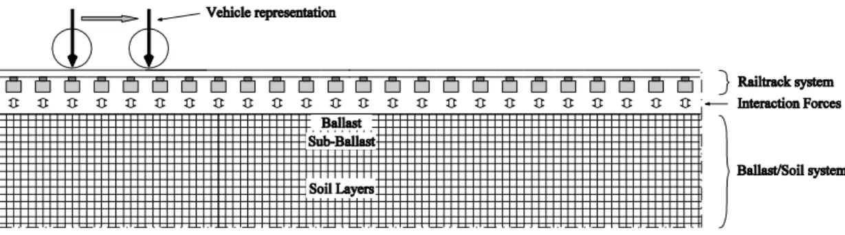
The Finite Element analyses were performed using a dynamic three-dimensional numerical program - Pegasus - developed and fully coded in MATLAB® environment (Varandas, 2013; Varandas et al., 2014). In this program, the vehicle, the track, and the ballast/soil layers are three distinct structural systems, which interact between each other by means of interaction forces. The interaction forces were considered only in the vertical direction, as shown in Figure 1.
Figure 1: Rail track system and ballast-soil system, shown in the direction of the track
In this paper, the vehicle system is considered by means of constant moving loads corresponding to the estimated vehicles weight. The track system and the ballast-soil system are spatially discretized using the Finite Element Method (FEM). The track is built with Euler-Bernoulli beam elements representing the rails and the sleepers. The rails are connected to the sleepers with spring-damper elements, representing the rail pads. The ballast-soil system is discretized with low-order eight-node solid hexahedral elements. The interaction forces between the sleepers and the underlying ballast are
dynamic simulations. The time integration method is the explicit integration scheme described in (Zhai, 1996). This method is conditionally stable, and therefore the integration time step must be less than a critical value for convergence of the solution. In present analyses the necessary value for Δt was 2.50 × 10⁻⁵ s and 1.67 × 10⁻⁵ s when considering the linear model or the nonlinear model for the ballast, respectively.
2.2
Track and Ballast-Soil System Models
The case study adopted in this study is a track section on a 4.5 m high embankment that was opened to traffic by the end of 2010. The section is located in Portugal, near Alcácer do Sal. The track is a single ballasted railway line (Figure 2), with Iberian gauge (1.668 m), comprising UIC60 rails (vertical bending stiffness of 6380 kNm2, and mass of 60.3 kg/m), resting on concrete monoblock sleepers (assumed rectangular prisms of 2.6 m by 0.30 m, with equivalent height of 0.212 m, Young’s
modulus of 30 GPa and a total mass of 322 kg), spaced 0.6m, and with fastening system Vossloh W14 with elastomer railpads (vertical stiffness of 160 kN/mm and damping constant of 17 kNs/m). This line allows mixed traffic, with maximum axle loads of 25 t and maximum speeds of 220 km/h for tilting passenger trains (Paixão et al., 2014).
The ballast and the sub-ballast layers were made of crushed granite aggregate. The capping layer was made with well-graded crushed limestone aggregate. The natural soil, classified as QS2 according
to UIC719R, corresponds to a gypsum-clay geologic formation from the Mio-Pliocene, predominantly comprising sands, and also silts and clays.
The properties of the geomaterials of the ballast-soil system are presented in Table 1. All materials were considered linear-elastic behaviour, except the ballast layer whose nonlinear resilient behaviour was considered using the nonlinear-elastic formulation of the ܭǦߠ model (Brown & Pell, 1967), generally expressed by the well-known formulation ܧൌ ܭଵߠమ, whereߠ is the sum of the principal
stresses and ܭଵ and ܭଶ are model parameters. The ܭǦߠ model was implemented in the numerical code
Pegasus using an adapted formulation described in detail by Varandas (2013), following the parameter calibration performed by Aursudkij et al. (2009), with ܭଵ = 110 MPa and ܭଶ = 0.6, assuming minimum value of ܧ= 16 MPa and a constant Poisson’s ratio of 0.20. Here, the response obtained with a nonlinear model for the ballast was compared with analyses considering the linear-elastic model for the ballast, adopting an equivalent linear ballast modulus of 130 MPa, which was found to give very good approximations for the overall track behaviour in earlier studies (Varandas, 2013).
The embankment soil modulus was defined as 60 MPa. Estimations of the deformation modulus Ev2, made with the portancemètre equipment continuously on top of the sub-ballast layer (Fortunato et al., 2012), have shown that the Ev2 modulus vary significantly along the track. The selected value of
60 MPa is in line with observed values of the in situ Ev2 estimations, in the lower range of values.
The three-dimensional model comprises 151 sleepers, corresponding to 90.9 m length, and consisting of 3618 frame elements and 3469 nodes to model the track system, and 260 864 solid elements and 280 098 nodes to represent the ballast-soil system using the mesh depicted in Figure 3.
Young’s modulus Poisson’s ratio Damping* Density Thickness
Geomaterials ୧ (MPa) ɋ୧ (-) Ɍ୧ (%) ɏ୧ (kg/m3) h (m)
Ballast 130+ 0.20 3 1530 0.30
Sub-ballast 200 0.30 3 1935 0.30
Capping layer 1000 0.30 3 1935 0.20
Embankment soils 60 0.30 3 2040 4.5
Notes: *Damping coefficients for frequencies 2 and 100 Hz, according to the Rayleigh damping concept; + Equivalent linear
modulus assumed for the ballast layer in the linear-elastic analyses.
Figure 2: Schematic track cross-section (after Paixão, 2014).
Figure 3: Representation of the numerical model and respective FEM mesh.
2.3
Loads Applied on the Track-Ballast-Soil System
Nonlinear analyses, where the system properties depend on the actual stresses among components, require that the initial stress state is calculated prior to the passing vehicles. To this effect, the initial stress state in the ballast/soil layers was computed assuming an in situ earth pressure coefficient K0 set
to 0.5 (corresponding to normally consolidated conditions). It was considered the weight of the track system and of the ballast, sub-ballast and capping layers. The weights of the crib and shoulder ballast, which are components of the railway system not represented in the finite element model, are considered as a constant surface pressure around the sleepers’ locations.
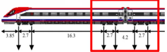
In the analyses it was considered the loading of the Alfa Pendular passenger tilting train, which was applied by means of four constant moving loads of 132 kN, relative to four consecutive axles belonging to two adjacent bogies as depicted in Figure 4. Therefore, The influence of the vehicle’s inertial forces was neglected, which is only significant when the uneven track profile and/or railhead irregularities are taken in consideration.
Figure 4: Schematic representation of the axle arrangement (in m) of the Alfa Pendular.
2.4
Track Critical Speed
The displacements in the track and foundation increase with the speed of the train until a certain given train speed – the track critical speed – where the dynamic amplification in the track and ballast-soil system reaches a maximum. The value of this critical velocity basically depends on the stiffness of the track support system, being less influenced by the properties of the track system itself (Mezher et al., 2015). For the track-foundation system described above, the track critical velocity was estimated to be 405 km/h. As expected, this value is closely related to the Rayleigh wave velocity of a homogeneous half-space made with the embankment soil, which is 355 km/h.
The following analyses will consider three possible train velocities: 220 km/h, 320 km/h and 350 km/h. Given the track critical speed of 405 km/h, these train velocities correspond to around 54%,
sub-ballast capping
embankment soils ballast layer
1 2
2 3
79% and 86% of the critical speed. The analyses in this paper therefore aim at showing if and how the dynamic aspect influences the stresses variations inside the ballast layer, in sub-critical regime. The length of the numerical model of 151 sleepers was therefore necessary to assure a steady-state condition at the section of study, given the considered high-speed of the train.
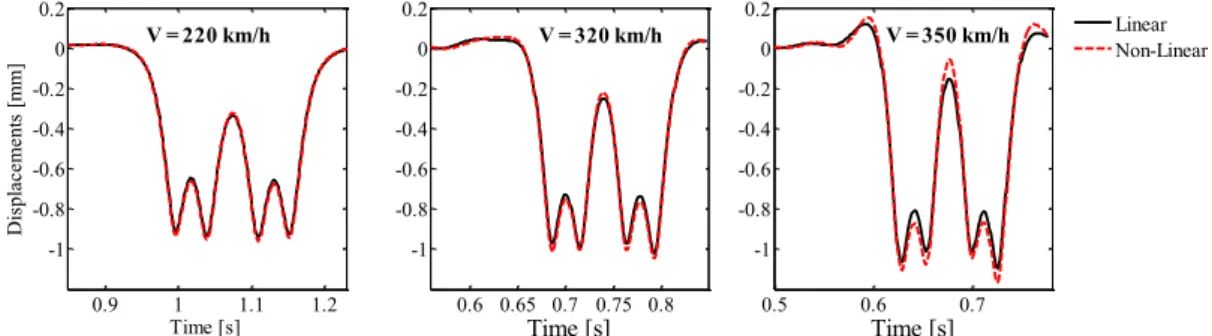
Figure 5 shows the dynamic displacements of the rail (relative to the initial equilibrium position), considering the passage of the Alfa Pendular train model at 220, 320 and 350 km/h. The figure also compares results obtained considering the ballast material as linear-elastic or as nonlinear-elastic.
Figure 5: Time history of dynamic rail displacements at different speeds, obtained considering the linear-elastic behaviour of ballast (black lines) and the nonlinear-elastic behaviour of ballast (red lines).
It can be seen that for the speed of 220 km/h, corresponding to 54% of the critical speed, the dynamic component is small (quasi-symmetrical displacement field), and results obtained with the ballast linear and nonlinear model are almost coincident. For the speed of 320 km/h (79% of critical speed), it can be seen that some dynamic amplification is already taking place, showing higher downward displacements compared to the first case, and non-negligible upward displacements. Also, at this speed, some differences between linear and nonlinear results are now noticeable. Finally, for the highest considered velocity (86% of critical speed) the dynamic component assumes evident importance and the differences between linear and nonlinear results are significant. In view of this, it can be argued that the influence of dynamic/inertial effects in the track-ballast-soil system will only be significant when the speed of the train closely approaches the track critical speed.
3
Dynamic Stresses inside the Ballast Layer
The stresses inside the track upper layers were determined at the finite elements under a central sleeper of the model, at the locations in the transversal (y-z) plane identified in Figure 6. For example, Figure 7 shows the variation of the six components of stress in ballast element A, corresponding to the location with higher compressions, for a train speed of 220 km/h and determined with the linear model or the nonlinear model for the ballast. It can be seen that the distribution of stresses significantly alters by considering the nonlinear model: the vertical stress is significantly higher than in the linear case and the tensile stress in x direction (Vx) is negligible compared to the linear case.
The shear stress variation in terms of its three components is associated with a three-dimensional rotation of the principal stresses. Figure 8 graphically defines angle Dx and Dy, being the angles that
the major principal direction (associated with the vertical compression) makes with the vertical axis, measured in the x-z plane and in the y-z plane, respectively.
0.5 0.6 0.7
-1 -0.8 -0.6 -0.4 -0.2 0 0.2
Time [s]
Linear Non-Linear
0.6 0.65 0.7 0.75 0.8 -1
-0.8 -0.6 -0.4 -0.2 0 0.2
Time [s]
0.9 1 1.1 1.2
-1 -0.8 -0.6 -0.4 -0.2 0 0.2
Time [s]
D
is
p
la
ce
me
n
ts
[
mm]
Figure 6: Location of the selected elements. Figure 7: Time history of stresses in element A for the train at 220 km/h: (a) linear ballast; (b) nonlinear ballast.
Figure 9 shows the principal stresses rotation (PSR) at elements D and F for the Alfa Pendular passage at 220 km/h. The figure also compares equivalent results obtained with the ballast linear and nonlinear model. First observation from Figure 9 is that the consideration of the ballast nonlinear model has again a significant effect on the estimation of the PSR inside the ballast layer. This is particularly evident for PSR in element F, where the variation in terms of Dx reduces by a factor two when considering the ballast nonlinear behaviour. The figure also shows that the dominant component of rotation in element D is angle Dy, and that in element F the dominant angle is Dx, because this element is very close to the track central symmetry axis, where angle Dy is theoretically zero.
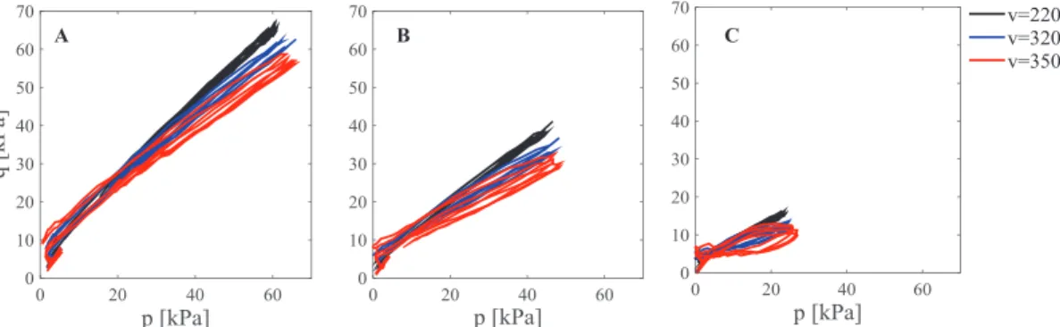
Figure 10 shows the stress paths (p-q) in elements A, B and C in the ballast, for the passage of the Alfa Pendular at 220, 320 and 350 km/h, and considering the ballast nonlinear response. It can be seen that increasing the speed of the train the mean normal pressure p increases but the deviatoric shear stress q decreases. Also, as expected, the stresses decrease from the tip of the sleeper to its centre.
Figure 8: Definition of angle Dx and Dy in
transverse and longitudinal views.
Figure 9: Time history of principal stresses rotation (PSR) in
elements D and F (according to Figure 6). 0 1 2 3 -0.2 0.0 0.2 A D B E C F wheel load y (m) z (m) ba llast sub-ba llast
0.05 0.1 0.15 0.2 0.25 0.3 -100 -80 -60 -40 -20 0 20 Time [s] V x V y V z W xy W yz W xz
0.05 0.1 0.15 0.2 0.25 0.3 -100 -80 -60 -40 -20 0 20 Time [s] S tr esses [ k P a] V x V y V z W xy W yz W
xz (a) (b)
0.1 0.2 0.3
-20 -10 0 10 20 Time [s] Angle [ d eg ]
0.05 0.1 0.15 0.2 0.25 0.3 -20 -10 0 10 20 Time [s]
Linear - Dx
Nonlinear - Dx
Linear - Dy Nonlinear - Dy
D F
B
Figure 11 presents time histories of the six stress components in element A, for train speeds of 220 and 350 km/h. It is interesting to note that the vertical stresses decrease slightly with speed but the horizontal stresses are amplified. This aspect will be discussed in the following section.
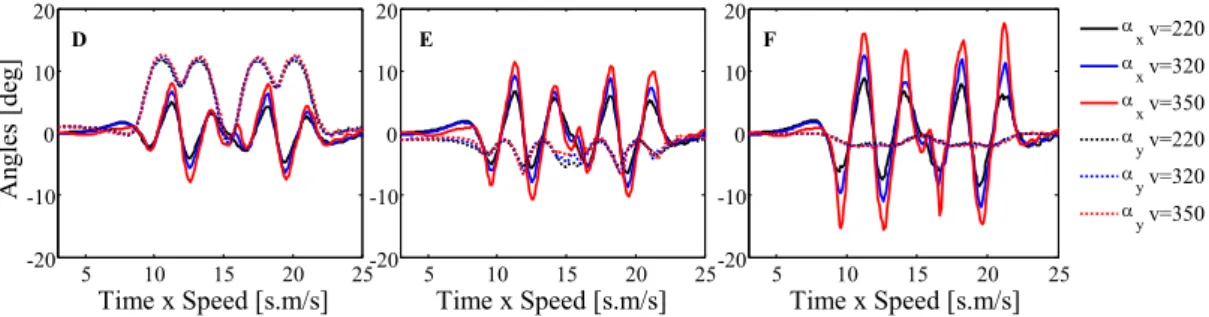
The rotation of the principal stresses, in terms of Dx and Dy, are shown in Figure 12 in elements D,
E and F for the train model at 220, 320 and 350 km/h. The abscissas values represent a normalized relative position of the train along the model, in order to synchronize results obtained at different velocities. These results show that higher train velocities lead to higher PSR inside the ballast layer, mainly in terms of the angle measured in the x-z plane Dx.
Figure 11: Time history of stresses in element A for the train at: (a) 220 km/h; (b) 350 km/h.
Figure 12: Variation of PSR in ballast elements D, F and E, for the passage of the train at several speeds.
4
Discussion and Conclusions
The paper showed that the consideration of a ballast nonlinear model significantly changed the distribution of stresses during train loading. In particular, unrealistic tensile stresses that may occur in the upper elements if considering the linear model, almost vanish in the equivalent nonlinear results. Also, the PSR decrease in the nonlinear results, because in this case the elements under the loaded sleeper are stiffer than those located between the sleepers, inducing a more vertical stress transmission, and therefore reducing the PSR effect.
The analyses also showed that when the train speed approaches the track critical velocity, further to an increase of the overall track response, the stress paths and the PSR are significantly affected. For example Figure 10 showed that the maximum deviatoric shear stress decreases with the train speed, which according to Figure 11 is due to an increase of the horizontal confining pressure, not followed by an increase of the vertical stress. The justification for the alteration of the stress distribution from the quasi-static regime to the near critical regime, being the same external loading applied at different speeds, lies in dynamic inertial effects in the soil induced by the passing vehicle when travelling at speeds close to the Rayleigh wave velocity in the ground.
0.05 0.1 0.15 0.2 0.25 0.3 -100 -80 -60 -40 -20 0 20 Time [s]
0.05 0.1 0.15 0.2 0.25 -100 -80 -60 -40 -20 0 20 Time [s] Stresses [ k Pa ] (b) (a)
220 km/h 350 km/h
V x V y V z W xy W yz W xz
5 10 15 20 25
-20 -10 0 10 20
Time x Speed [s.m/s]
Angl es [ d eg ]
5 10 15 20 25
-20 -10 0 10 20
Time x Speed [s.m/s]
5 10 15 20 25
-20 -10 0 10 20
Time x Speed [s.m/s]
The consideration of a classical continuum mechanics approach with a nonlinear constitutive law, although not allowing for microstructural analyses, such as particle orientation, orientation of contacts or distribution of inter-particle contact forces, has given adequate estimations of the average stresses induced in the ballast, that may be used to calibrate experimental tests performed in triaxial or hollow cylinder equipment. Of course, this study as focused on a particular vehicle, railway track and ballast/soil model, and therefore further analyses are recommended to strengthen the conclusions derived from this numerical study, in what concerns the influence of the train speed in the induced stresses inside the ballast. Moreover, aspects that may play an important role in realistic scenarios that were not analysed include the track geometrical quality, the existence of unsupported sleepers, the train-track interaction, or railway transition scenarios.
Acknowledgements
Part of this work was conducted in the framework of the TC202 national committee of the Portuguese
Geotechnical Society (SPG) “Transportation Geotechnics”, in association with the International
Society for Soil Mechanics and Geotechnical Engineering (ISSMGE-TC202).
References
Aursudkij, B.; McDowell, G.R. & Collop, A.C. (2009) Cyclic loading of railway ballast under triaxial conditions and in a railway test facility; Granular Matter; Vol. 11; n.º 6; p. 391-401.
Brown, S. & Pell, P. (1967) An experimental investigation of the stresses, strains and deflections in layered pavement structure subjected to dynamic loads; 2nd Int. Conf. on Structural Design of Asphalt Pavements; Michigan, Ann Arbor; pp. 487–504.
Fortunato, E.; Paixão, A. & Fontul, S. (2012) Improving the use of unbound granular materials in railway sub-ballast layer; Advances in Transportation Geotechnics II; Hokkaido University, Japan; 10-12 Sep. 2012; pp. 522-527.
Gräbe, P.J. & Clayton, C.R.I. (2009) Effects of Principal Stress Rotation on Permanent Deformation in Rail Track Foundations; J. of Geotechnical and Geoenvironmental Eng.; Vol. 135; n.º 4; p. 555-565.
Mezher, S.B.; Connolly, D.P.; Woodward, P.K.; Laghrouche, O.; Pombo, J. & Costa, P.A. (2015)
Railway critical velocity – Analytical prediction and analysis; Transportation Geotechnics.
Paixão, A.; Fortunato, E. & Calçada, R. (2014) Transition zones to railway bridges: track measurements and numerical modelling; Engineering Structures; Vol. 80; p. 435-443.
Powrie, W.; Yang, L. & Clayton, C. (2007) Stress changes in the ground below ballasted railway track during train passage; J. of Rail and Rapid Transit; Vol. 221; n.º 2; p. 247-262.
Selig, E.T. & Waters, J.M. (1994) Track geotechnology and substructure management; London: Thomas Telford.
Varandas, J.; Paixão, A.; Fortunato, E.; Hölscher, P. & Calçada, R. (2014) Numerical modelling of railway bridge approaches: influence of soil non-linearity; Int. Journal of Railway Technology; Vol. 3; n.º 4; p. 73-95.
Varandas, J.N. (2013) Long-term behaviour of railway transitions under dynamic loading; Ph.D. Thesis; Lisboa: FCT, Nova University of Lisbon.
Yang, L.A.; Powrie, W. & Priest, J.A. (2009) Dynamic Stress Analysis of a Ballasted Railway Track Bed during Train Passage; J. of Geotechnical and Geoenv. Eng.; Vol. 135; n.º 5; p. 680-689.