Nuno Miguel Ferrete Ribeiro
IMUs – Validation, Gait Analysis and
System’s Implementation
Dissertação de Mestrado
Mestrado Integrado em Engenharia Biomédica
Ramo Eletrónica Médica
Trabalho efetuado sob orientação de:
Doutora Cristina P. Santos
Universidade do Minho
setembro de 2017
Universidade do Minho
III
DECLARAÇÃO
Nome: Nuno Miguel Ferrete Ribeiro
Endereço eletrónico: [email protected] Número do cartão de cidadão: 14516699
Título da Dissertação: IMUs – Validation, Gait Analysis and System’s Implementation
Orientador:
Doutora Cristina Manuela Peixoto dos Santos Ano de conclusão: 2017
Designação do Mestrado: Mestrado Integrado em Engenharia Biomédica Área de Especialização: Ramo Eletrónica Médica
É AUTORIZADA A REPRODUÇÃO INTEGRAL DESTA DISSERTAÇÃO APENAS PARA EFEITOS DE INVESTIGAÇÃO, MEDIANTE DECLARAÇÃO ESCRITA DO INTERESSADO, QUE A TAL SE COMPROMETE.
Universidade do Minho, ___ /___ /______ Assinatura: _______________________________________________________________
V
“I’m free to be the greatest.
I’m alive.”
VII
Acknowledgments
First of all, I would like to mention an immense gratitude to Professor Cristina Santos, who was crucial, not only at the level of scientific guidance, but also at the level of support, advice, encouragement and suggestions, being always present throughout this year. Beyond doubt, you have allowed, through a methodical and organized orientation, the concretization of this project. Consequently, I would like to offer you all my thanks.
In particular, I could not fail to thank Joana Figueiredo and César Ferreira for the collaboration, availability, patience and good disposition. Thank you for the support and knowledge you provide me with, which were fundamental.
To my laboratory colleagues, thank you for all the encouragement, and for your knowledge-sharing and advices you gave me throughout this year.
I would also like to express my gratitude to my friends, who have been unconditionally by my side during this phase as always.
I thank Ana Silva for all the sensitivity, affection, patience, support and love she has shown over the last few years, being always ready to help me and give me the strength to continue. I am very proud of you. By your presence, a huge thank you.
Finally, I want to thank my family for the unconditional support they have shown throughout my life, for being always present in all important moments, for always believing in my abilities and for never letting me give up or discourage by the difficulties or obstacles that have crossed my path. In particular, I should also thank my parents for providing me with the best conditions for my academic training, for always indicating to me the best way forward and for having given me the opportunity to join the Biomedical Engineering integrated master’s degree. My family represents the great pillar on which I stand and in which I am very proud.
To all of you, my most sincere and humble thank you!
IX
Agradecimentos
Primeiramente, gostaria de mencionar uma imensa gratidão para com a professora Cristina Santos, que foi crucial, não apenas ao nível da orientação científica, mas também ao nível de apoio, conselhos, encorajamento e sugestões, estando sempre presente ao longo deste ano. Sem margem para dúvidas, você permitiu, através de uma orientação metódica e organizada, a concretização deste projeto. Como tal, gostaria de lhe dirigir um enorme obrigado.
Não podia deixar de agradecer a colaboração, disponibilidade, paciência e boa disposição, em particular, da Joana Figueiredo e do César Ferreira. Um obrigado pelo apoio e pelos conhecimentos que me disponibilizaram, os quais foram fundamentais.
Aos meus colegas de laboratório, obrigado por todo o incentivo e pela partilha de conhecimentos e conselhos que me deram ao longo deste ano.
Queria deixar também uma palavra de agradecimento aos meus amigos, que estiveram incondicionalmente ao meu lado durante esta fase como sempre.
Agradeço à Ana Silva por toda a sensibilidade, carinho, paciência, apoio e amor que tem demonstrado ao longo destes últimos anos, estando sempre disposta a me ajudar e a me dar forças para continuar. Tenho muito orgulho em ti. Pela tua presença, um enorme obrigado.
Por fim, quero agradecer à minha família pelo apoio incondicional demonstrado ao longo de toda a minha vida, por estarem sempre presentes em todos os momentos importantes, por acreditarem sempre nas minhas capacidades e por nunca me deixarem desistir ou desanimar perante as dificuldades ou obstáculos que se atravessaram no meu caminho. Em particular, devo agradecer ainda aos meus pais por me fornecerem as melhores condições para a minha formação acadêmica, por me indicarem sempre o melhor caminho a seguir e por me terem proporcionado a oportunidade de ingressar no Mestrado Integrado em Engenharia Biomédica. A minha família representa o grande pilar em que me sustento e no qual tenho muito orgulho.
A todos vós, o meu mais sincero e humilde Obrigado!
XI
Abstract
Falls are a prevalent problem in actual society. The number of falls has been increasing greatly in the last fifteen years. Some falls result in injuries and the cost associated with their treatment is high. However, this is a complex problem that requires several steps in order to be tackled. Namely, it is crucial to develop strategies that recognize the mode of locomotion, indicating the state of the subject in various situations, namely normal gait, step before fall (pre-fall) and fall situation. Thus, this thesis aims to develop a strategy capable of identifying these situations based on a wearable system that collects information and analyses the human gait.
The strategy consists, essentially, in the construction and use of Associative Skill Memories (ASMs) as tools for recognizing the locomotion modes. Consequently, at an early stage, the capabilities of the ASMs for the different modes of locomotion were studied. Then, a classifier was developed based on a set of ASMs. Posteriorly, a neural network classifier based on deep learning was used to classify, in a similar way, the same modes of locomotion. Deep learning is a technique actually widely used in data classification. These classifiers were implemented and compared, providing for a tool with a good accuracy in recognizing the modes of locomotion.
In order to implement this strategy, it was previously necessary to carry out extremely important support work. An inertial measurement units’ (IMUs) system was chosen due to its extreme potential to monitor outpatient activities in the home environment. This system, which combines inertial and magnetic sensors and is able to perform the monitoring of gait parameters in real time, was validated and calibrated. Posteriorly, this system was used to collect data from healthy subjects that mimicked Fs.
Results have shown that the accuracy of the classifiers was quite acceptable, and the neural networks based classifier presented the best results with 92.71% of accuracy. As future work, it is proposed to apply these strategies in real time in order to avoid the occurrence of falls.
Keywords: falls; gait parameters; inertial measurement units (IMUs); sensory fusion’s algorithms;
XIII
Resumo
As quedas são um problema predominante na sociedade atual. O número de quedas tem aumentado bastante nos últimos quinze anos. Algumas quedas resultam em lesões e o custo associado ao seu tratamento é alto. No entanto, trata-se de um problema complexo que requer várias etapas a serem abordadas. Ou seja, é crucial desenvolver estratégias que reconheçam o modo de locomoção, indicando o estado do sujeito em várias situações, nomeadamente, marcha normal, passo antes da queda (pré-queda) e situação de queda. Assim, esta tese tem como objetivo desenvolver uma estratégia capaz de identificar essas situações com base num sistema wearable que colete informações e analise a marcha humana.
A estratégia consiste, essencialmente, na construção e utilização de Associative Skill Memories (ASMs) como ferramenta para reconhecimento dos modos de locomoção. Consequentemente, numa fase inicial, foram estudadas as capacidades das ASMs para os diferentes modos de locomoção. Depois, foi desenvolvido um classificador baseado em ASMs. Posteriormente, um classificador de redes neuronais baseado em deep learning foi utilizado para classificar, de forma semelhante, os mesmos modos de locomoção. Deep learning é uma técnica bastante utilizada em classificação de dados. Estes classificadores foram implementados e comparados, fornecendo a uma ferramenta com uma boa precisão no reconhecimento dos modos de locomoção.
Para implementar esta estratégia, era necessário realizar previamente um trabalho de suporte extremamente importante. Um sistema de unidades de medição inercial (IMUs), foi escolhido devido ao seu potencial extremo para monitorizar as atividades ambulatórias no ambiente domiciliar. Este sistema que combina sensores inerciais e magnéticos e é capaz de efetuar a monitorização de parâmetros da marcha em tempo real, foi validado e calibrado. Posteriormente, este Sistema foi usado para adquirir dados da marcha de indivíduos saudáveis que imitiram quedas.
Os resultados mostraram que a precisão dos classificadores foi bastante aceitável e o classificador baseado em redes neuronais apresentou os melhores resultados com 92.71% de precisão. Como trabalho futuro, propõe-se a aplicação destas estratégias em tempo real de forma a evitar a ocorrência de quedas.
XIV
Palavras-chave: quedas; parâmetros da marcha; Unidades de medição inercial (IMUs);
XV
Contents
Acknowledgments ... VII Agradecimentos ... IX Abstract ... XI Resumo ... XIII Contents... XV List of Figures ... XIX List of Tables ... XXV Acronyms and Abbreviations ... XXVIIIChapter 1 - Introduction ... 1
1.1. Motivation ... 1
1.2. Problem Statement and scope ... 3
1.3. Goals and research questions ... 3
1.4. Contribution to knowledge... 6
1.5. Publications ... 7
1.6. Thesis outline ... 7
Chapter 2 – Inertial Measurement Units: State-of-the-art ... 11
2.1. Introduction ... 11
2.2. Applications and Commercial IMUs ... 15
2.3. Advantages and Disadvantages ... 21
2.4. Methods and Problems ... 22
2.5. Calibration ... 25
2.6. Challenges ... 26
Chapter 3 – Falls Prevention and Risk Identification: state-of-the-art ... 29
3.1. Introduction ... 29
3.2. Classification of the Falls ... 30
3.3. Methods ... 32
3.3.1. Fall Detection Systems ... 32
3.3.2. Fall Prevention Systems/Fall Forecasting Systems ... 36
XVI
3.4.1. Gait Parameters ... 40
3.4.2. Sensors and Experimental Setup Information ... 42
3.5. Challenges, Issues and Trends ... 49
3.5.1. Challenges ... 49
3.5.2. Issues ... 49
3.5.3. Trends ... 50
Chapter 4 – Human Gait Monitoring System Overview ... 51
4.1. Introduction ... 51
4.2. Magnetic/Inertial Measurement System ... 51
4.3. eLPRT protocol ... 52
4.4. Algorithmic State Machine ... 53
4.5. System Requirements and MATLAB Interface ... 54
4.5.1. System Requirements ... 54
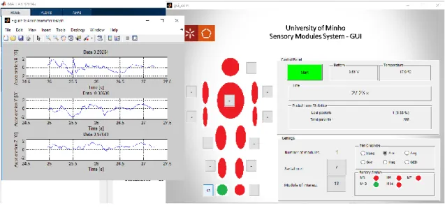
4.5.2. MATLAB Interface ... 56
4.5.2.1. Quality Assessment ... 59
4.5.2.2. Results and Discussion ... 59
Chapter 5 – IMUs based System Validation ... 61
5.1. Validation of the communication protocol ... 61
5.1.1. Trials ... 62
5.1.2. Results ... 63
5.1.3. Discussion ... 66
5.2. Validation of the signals of the sensors ... 67
5.2.1. Results and Discussion ... 68
5.2.1.1. Foot ... 68
5.2.1.2. Thigh ... 70
5.2.1.3. Lower Back ... 72
5.3. Validation of the estimation of joint angles ... 73
5.3.1. Reference Measurement System - DARwIn OP ... 74
5.3.2. Knee Joint Angle Measurement ... 75
5.3.3. Results ... 75
5.3.4. Discussion ... 77
XVII
6.1. Calibration procedures - Introduction ... 79
6.2. Methods ... 81
6.2.1. Process of the orientation estimation of the IMUs based system ... 81
6.2.2. Calibration Procedures ... 81 6.2.2.1. Method A ... 82 6.2.2.2. Method B... 82 6.2.2.3. Method C... 83 6.2.2.4. Proposed Method... 84 6.2.3. Tracker Software... 85 6.2.4. Experimental Protocol ... 85 6.3. Results ... 87 6.3.1. Stage 1 ... 87 6.3.2. Stage 2 ... 88 6.3.2.1. Stationary position ... 88 6.3.2.2. Walking trial ... 91 6.3.3. Stage 3 ... 93 6.3.4. Stage 4 ... 95 6.4. Discussion ... 96
Chapter 7 – Pre-Fall Detection System ... 99
7.1. Stage 1 ... 99
7.1.1. Trials ... 100
7.1.2. PCA ... 101
7.1.3. ASMs ... 103
7.1.4. Evaluation of classification performance ... 107
7.1.5. Results ... 108 7.1.5.1. PCA ... 108 7.1.5.2. ASMs ... 114 7.2. Stage 2 ... 133 7.2.1. Results ... 134 7.3. Stage 3 ... 135
XVIII 7.3.2. Results ... 137 7.4. Stage 4 ... 138 7.5. Discussion ... 140 Chapter 8 – Conclusions ... 143 8.1. Future work ... 148 References ... 151 Appendices ... 169 Appendix 1 ... 169
XIX
List of Figures
Figure 2.1 - Example of a RLVBIMU04 IMU from VBOX Automotive with wire connection [194]. 13
Figure 2.2 - a) A mechanical Acc; b) A surface acoustic wave Acc [194], [29]. ... 14
Figure 2.3 - A conventional mechanical Gyro [29]. ... 14
Figure 2.4 - Image of a micro Mag structure [195]. ... 15
Figure 2.5 - Xsens MVN products [38]. MVN Awinda is on the left side. MVN Link is on the right side. ... 17
Figure 2.6 - InterSense 3-DOF trackers [39]: a) InertiaCube4TM; b) InertiaCube BTTM. ... 18
Figure 2.7 - InterSense 6-DOF trackers [39]: a) IS-900 system; b) IS-1200+ system. ... 18
Figure 2.8 - Technaid products [40]: a) IMU CV4; b) IMU V4 ... 19
Figure 2.9 - Technaid Motion Capture System [40]. ... 19
Figure 2.10 - IMeasureU IMU sensor [41]. ... 20
Figure 2.11 - Noraxon myoMOTION device [42]. ... 20
Figure 3.1 - Balance performance model [83]. ... 30
Figure 3.2 - Possible Fs along the horizontal/lateral and vertical directions [88]: a) F forward; b) F laterally; c) F backward; d) F along vertical direction – slipping of foot; e) F along vertical direction – weak legs. ... 31
Figure 3.3 - Classification of F detection methods according to [89]. ... 33
Figure 3.4 - Distribution of research studies on wearable sensors: Application vs Wearable Sensors [82]. ... 34
Figure 3.5 - Typical output of a chest 3D Acc before and after a F event. Acceleration peaks are cause by floor impact [86]. It is possible to observe that acceleration suffers perturbations about 1 second before actual impact. ... 35
Figure 3.6 - STEADI F Risk Assessment algorithm [135]. ... 38
Figure 3.7 - Representation of the stability in a vertical position. ... 41
Figure 3.8 - Different axis/planes. The frontal plane is referred to as Antero-posterior (AP), the lateral plane as Medio-lateral (ML) and the vertical simply as Vertical (VT). ... 43
Figure 4.1 - Magnetic/Inertial Measurement System Elements... 52
Figure 4.2 - a) Constitution of the frame; b) Constitution of the payload (S-sample/reading, T1 & T2-temperature byte 1 and 2, Bat1 & Bat2-battery byte 1 and 2). ... 52
XX
Figure 4.3 - Data acquisition process flowchart. ... 55
Figure 4.4 - Matlab GUI when initialized (Ang – Angles; GED – Gait Events Detection). ... 56
Figure 4.5 - Matlab GUI when the system is in the operational state. ... 58
Figure 4.6 - Matlab GUI when the system was stopped. ... 58
Figure 4.7 - Inquiry results in percentage per question number. ... 60
Figure 5.1 – Phases of the validation process. ... 61
Figure 5.2 - Spatial arrangement of the sensory modules in the body with their physical addresses: a) 5 sensory modules on trunk (3), foot (13-right, 6-left), and shank (7-right, 14-left); b) 4 sensory modules on foot (13-right, 6-left), and shank (7-right, 14-left); c) 3 sensory modules on right leg: foot (13), shank (7), and thigh (14); d) 2 sensory modules on the upper foot (13-right, 6-left); e) 1 sensory module on the upper foot (13-right); f) 2 sensory modules on the heel (13-right, 6-left); and g) 1 sensory module on the heel (13-right). ... 62
Figure 5.3 - Average percentage of loss for each spatial arrangement in laboratory (N-Normal pace; F- Fast pace)... 65
Figure 5.4 - Average percentage of loss for each spatial arrangement in the corridor (N-Normal pace; F- Fast pace). ... 66
Figure 5.5 - Average percentage of loss for each spatial arrangement in an outdoor environment (N-Normal pace; F- Fast pace). ... 66
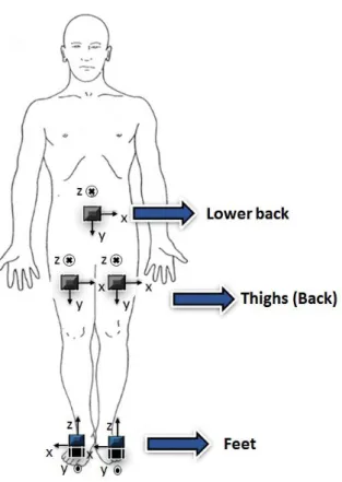
Figure 5.6 - Attachment location of the sensing devices used for the trials (Dark sensing devices are in the back of the body). ... 68
Figure 5.7 – a) Orientation of the Cartesian axes of the sensing device. b) Xsens’ IMU attached to the right foot. ... 68
Figure 5.8 – Norm of the acceleration during a walking trial obtained from: a) a Jiménez’s trial (black line) [163]. b) IMUs based system (data not filtered). ... 69
Figure 5.9 - Gyro data during a walking trial obtained from: a) a Jiménez’s trial [163]. b) IMUs based system (data not filtered). ... 69
Figure 5.10 - Mag data during a walking trial obtained from: a) a Jiménez’s trial [163]. b) IMUs based system (data not filtered). ... 70
Figure 5.11 - Attachment location of the IMUs [51]. a) Elevation view. b) Side view. c) Real photo of the proposed capturing system. ... 71
XXI
Figure 5.12 – Gyro data (mediolateral axis) when an IMU is attached in the right thigh. a) Hamdi’s typical signal (blue signal) [51]. b) IMUs system (data filtered: Butterworth lowpass filter – Fc=3Hz).
... 71
Figure 5.13 - Acc data (vertical axis) when an IMU is attached in the right thigh. a) Hamdi’s typical signal (blue signal) [51]. b) One gait cycle measured by the IMUs based system (data filtered: Butterworth lowpass filter – Fc=3Hz). ... 72
Figure 5.14 - Gyro data (vertical axis) when an IMU is attached in the lower back. a) Hamdi’s typical signal [51]. b) One gait cycle measured by the IMU’s system (data filtered: Butterworth lowpass filter – Fc=3Hz). ... 73
Figure 5.15 - a) DARwIn robot with two sensory modules attached to left thigh and shank (for both modules, the positive Z axis is perpendicular to the housing cover, Y axis – up, X axis – to the left of the robot). b) DARwIn robot performs an angle of -30º with the left leg (sagittal plane). In this situation, knee angles from the robot are represented as α, and the knee angles from the model implemented are represented as γ... 74
Figure 5.16 - Typical knee angles (º) during the trial where the DARwIn OP was walking (ANG Dar - robot real angles measured through encoders; ANG IMUs - calculated knee angles from sensory modules data; x-axis: time (s); y-axis: angles). ... 76
Figure 5.17 - Typical knee angles (º) during the trial where the DARwIn OP kept the leg stretched (ANG Dar - robot real angles measured through encoders; ANG IMUs - calculated knee angles from IMUs' data; x-axis: time (s); y-axis: angles). ... 76
Figure 5.18 - Typical knee angles (º) during the trial where the DARwIn OP performed an angle of -30º (ANG Dar - robot real angles measured through encoders; ANG IMUs - calculated knee angles from IMUs' data; x-axis: time (s); y-axis: angles). ... 77
Figure 6.1 – Several steps of the calibration procedures from the raw measurements x to measurements va resolved in the anatomical frame [170]. ... 80
Figure 6.2 - Block diagram of the calibration process. ... 81
Figure 6.3 - Basic Principle of Method A: Extraction of Acc Maximum and Minimum values for each axis through 6 different positions... 82
Figure 6.4 - Sensors' attachment location to measure Gyro’s offsets. ... 86
Figure 6.5 - Walking trial angles of the thigh: a) roll; b) pitch; and c) yaw. ... 93
XXII
Figure 6.7 - Rotation angles of stage 3 experiment: a) Roll; b) Pitch; and c) Yaw. ... 94 Figure 6.8 - Yaw angles obtained through a CF, Madgwick filter (w/ and w/o Mag), and Mahony filter (w/ and w/o Mag)... 96 Figure 7.1 - Block diagram of the first stage. ... 99 Figure 7.2 – Trial i) in the gymnasium – Subject (blue point) walks forward (Top – w/o F; Down – w/ F where the F’s location is represented by the red X)... 100 Figure 7.3 – Trial ii) in the gymnasium – Subject (blue point) walks in circles (Top – w/o F – right and left; Down – w/ F where the F’s location is represented by the red X). ... 100 Figure 7.4 – Trial iii) in the gymnasium – Subject (blue point) walks 10m forward bypassing an obstacle (Top – w/o F – right and left; Down – w/ F where the F’s location is represented by the red X). ... 100 Figure 7.5 - Sensing devices attachment location used for the trials (Dark sensing devices are in the back of the body; Red numbers represent the physical addresses of the sensing devices). 101 Figure 7.6 - Set of steps to obtain the most relevant variables (Case I). ... 102 Figure 7.7 - Set of steps to obtain the most relevant variables (Case II). ... 103 Figure 7.8 – Test data set of the left gripper right finger force cell. Example presented in [185]. The weighted standard deviation (blue line) was computed from the training set. The failure condition for all unsuccessful trials was detected correctly after an average of 2.4 seconds (shaded area). ... 104 Figure 7.9 - Scree Plot of the PCA procedure I when using the global walking locomotion mode. ... 108 Figure 7.10 - Scree Plot of the PCA procedure II when using the global data. ... 109 Figure 7.11 - Scree Plot of the PCA procedure II when using the Walking Forward (WF) data. . 110 Figure 7.12 – Scree Plot of the PCA procedure II when using the PF data. ... 111 Figure 7.13 - Scree Plot of the PCA procedure II when using the F data. ... 112 Figure 7.14 – Non-repeated and relevant metrics identified through PCA procedure and the indication to which group they belong... 113 Figure 7.15 – Examples of ASMs. a) Gyr_X_6 from WF set of ASMs; b) SVM_6 from Global set of ASMs; c) Mag_Z_13 from PF set of ASMs; d) Mag_Y_3 from F set of ASMs. ... 114 Figure 7.16 – ROC curve of the first ROC analysis – ASM WF**. ... 116 Figure 7.17 – Histogram of the number of failures per metric – ASM WF**. ... 116
XXIII
Figure 7.18 – Examples of ASMs. a) Gyr_X_6; b) Acc_Z_13; c) WD_Mag_Z_13; d) Mag_Z_13 (Green – Successful motion periods; Red – Unsuccessful motion periods; Blue – Weighted STD). ... 117 Figure 7.19 - ROC curve of the second ROC analysis – ASM WF*. ... 118 Figure 7.20 - Histogram of the number of failures per metric – ASM WF*. ... 119 Figure 7.21 - Examples of ASMs. a) Mag_Z_3; b) Mag _Z_13 (Green – Successful motion periods; Red – Unsuccessful motion periods; Blue – Weighted STD). ... 119 Figure 7.22 - ROC curve of the third ROC analysis – ASM WF. ... 120 Figure 7.23 - Histogram of the number of failures per metric – ASM WF. ... 121 Figure 7.24 – Examples of ASMs. a) Acc_Z_13; b) Mag _Z_13 (Green – Successful motion periods; Red – Unsuccessful motion periods; Blue – Weighted STD). ... 121 Figure 7.25 – ROC curve of the fourth ROC analysis – ASM Global*... 122 Figure 7.26 – Histogram of the number of failures per metric – ASM Global*... 123 Figure 7.27 – Examples of ASMs. a) Mag_Y_7; b) WD_Mag _Z_13 (Green – Successful motion periods; Red – Unsuccessful motion periods; Blue – Weighted STD). ... 123 Figure 7.28 – ROC curve of the fifth ROC analysis – ASM Global. ... 124 Figure 7.29 - Histogram of the number of failures per metric – ASM Global. ... 125 Figure 7.30 – Examples of ASMs. a) Mag_Z_13; b) WD_Mag _Z_13 (Green – Successful motion periods; Red – Unsuccessful motion periods; Blue – Weighted STD). ... 125 Figure 7.31 – ROC curve of the sixth ROC analysis – ASM F. ... 126 Figure 7.32 – Histogram of the number of failures per metric – ASM F. ... 127 Figure 7.33 – Examples of ASMs. a) ApEn_Acc_X_7; b) Mag _Z_3 (Green – Successful motion periods; Red – Unsuccessful motion periods; Blue – Weighted STD). ... 127 Figure 7.34 – ROC curve of the seventh ROC analysis – ASM PF∆. ... 128 Figure 7.35 – Histogram of the number of failures per metric – ASM PF∆. ... 129 Figure 7.36 – Examples of ASMs. a) ASMA_6; b) SVd_13 (Green – Successful motion periods; Red – Unsuccessful motion periods; Blue – Weighted STD). ... 129 Figure 7.37 – ROC curve of the eighth ROC analysis – ASM PF. ... 130 Figure 7.38 – Histogram of the number of failures per metric – ASM PF. ... 131 Figure 7.39 – Examples of ASMs. a) ApEn_Acc_Z_3; b) Mag_Z_6 (Green – Successful motion periods; Red – Unsuccessful motion periods; Blue – Weighted STD). ... 131
XXIV
Figure 7.40 – Decision cascade to classify collected motion periods. ... 133 Figure 7.41 - Layers that constitute a neural network, which consist of a set of interconnected nodes [190]... 136 Figure 7.42 – Processes of resampling and resizing to use data as input in the CNN. ... 137 Figure 7.43 – Top view of the walking trial performed in stage 4. ... 138
XXV
List of Tables
Table 3.1 - Commercial wearable F detection products ... 36 Table 3.2 - Potentially relevant metrics for the prevention of gait, and the sensors, the location of the sensors, subjects’ age, and the procedure used to obtain them (K – Kinematic; F – Frequency; ST – Spatiotemporal; Ph – Physiological; Ki – Kinetic; y – young; o – old; h – healthy; fp – fall prone; *-already mentioned) ... 43 Table 5.1 - Direction of the positive axis for each sensory module in each spatial arrangement . 63 Table 5.2 - Number of lost frames and total frames for each environment ... 64 Table 5.3 - Average percentage of loss of the five tests for each spatial arrangement (L-Lab; C-Corridor; O-Outdoor; N-Normal pace; F- Fast pace) ... 64 Table 6.1 - Error Percentage of the Maximum and Minimum values when compared to the homologous values of the Method A – Acc case ... 87 Table 6.2 - Error Percentage of the Maximum and Minimum values when compared to the homologous values of the Method A – Mag case ... 87 Table 6.3 - Error Percentage of the Gyro’s Offsets in three body segments when compared to the homologous values when IMU was at Position 1 ... 88 Table 6.4 - Mean of the RMSEs between methods for normalized data – Acc x-axis ... 88 Table 6.5 - Mean of the RMSEs between methods for normalized data – Acc y-axis ... 89 Table 6.6 - Mean of the RMSEs between methods for normalized data – Acc z-axis ... 89 Table 6.7 - Mean of the RMSEs between methods for normalized data – Mag x-axis ... 89 Table 6.8 - Mean of the RMSEs between methods for normalized data – Mag y-axis ... 89 Table 6.9 - Mean of the RMSEs between methods for normalized data – Mag z-axis ... 90 Table 6.10 - Mean of the RMSEs between methods for orientation angles – Roll (SI: degrees) .. 90 Table 6.11 - Mean of the RMSEs between methods for orientation angles – Pitch (SI: degrees) 90 Table 6.12 - Mean of the RMSEs between methods for orientation angles – Yaw (SI: degrees) .. 90 Table 6.13 - Mean of the RMSEs between methods for normalized data – Acc x-axis ... 91 Table 6.14 - Mean of the RMSEs between methods for normalized data – Acc y-axis ... 91 Table 6.15 - Mean of the RMSEs between methods for normalized data – Acc z-axis ... 91 Table 6.16 - Mean of the RMSEs between methods for normalized data – Mag x-axis ... 91 Table 6.17 - Mean of the RMSEs between methods for normalized data – Mag y-axis ... 92
XXVI
Table 6.18 - Mean of the RMSEs between methods for normalized data – Mag z-axis ... 92 Table 6.19 - Mean of the RMSEs between methods for orientation angles – Roll (SI: degrees) .. 92 Table 6.20 - Mean of the RMSEs between methods for orientation angles – Pitch (SI: degrees) 92 Table 6.21 - Mean of the RMSEs between methods for orientation angles – Yaw (SI: degrees) .. 92 Table 6.22 - RMSEs between calibration methods and the optical reference ... 95 Table 6.23 - RMSEs between different sensor fusion algorithms and the optical reference ... 95 Table 7.1 – Classification of collected data ... 103 Table 7.2 – Relevant metrics identified from both PCA procedures (Global Data) ... 109 Table 7.3 – Relevant metrics identified from PCA procedure II (WF Data) ... 111 Table 7.4 – Relevant metrics identified from PCA procedure II (PF Data)... 112 Table 7.5 – Relevant metrics identified from PCA procedure II (F’s Data) ... 113 Table 7.6 – Different ROC analyses and their considerations ... 115 Table 7.7 – Predicted conditions - ASM WF** (FP–False Positive; TN–True Negative; TP–True Positive; FN–False Negative) ... 115 Table 7.8 – Predicted conditions-ASM WF* (FP–False Positive; TN–True Negative; TP–True Positive; FN–False Negative) ... 118 Table 7.9 - Predicted conditions-ASM WF (FP–False Positive; TN–True Negative; TP–True Positive; FN–False Negative)... 120 Table 7.10 - Predicted conditions-ASM Global* (FP–False Positive; TN–True Negative; TP–True Positive; FN–False Negative) ... 122 Table 7.11 – Predicted conditions-ASM Global (FP–False Positive; TN–True Negative; TP–True Positive; FN–False Negative) ... 124 Table 7.12 – Predicted conditions-ASM F (FP–False Positive; TN–True Negative; TP–True Positive; FN–False Negative)... 126 Table 7.13 – Predicted conditions-ASM PF∆ (FP–False Positive; TN–True Negative; TP–True Positive; FN–False Negative) ... 128 Table 7.14 – Predicted conditions-ASM PF (FP–False Positive; TN–True Negative; TP–True Positive; FN–False Negative) ... 130 Table 7.15 – Best combinations of parameters and the minimal Euclidean distance for each ROC analysis ... 132 Table 7.16 – Metrics of each ROC analysis (TPR – True Positive Rate) ... 132
XXVII
Table 7.17 – Results of the decision cascade when PF’s data were considered as different from the other types of data ... 134 Table 7.18 – Results of the decision cascade when PF’s data were considered like WF and Global’s data ... 135 Table 7.19 – Results of the Case 2 of the stage 3 (Input image: 28x28) ... 137 Table 7.20 – Results of the Case 2 of the stage 3 (Input image: 100x41) ... 138 Table 7.21 – Results of the Case 1 of the stage 4 (ASMs based classifier) ... 139 Table 7.22 – Results of the Case 2 of the stage 4 (ASMs based classifier) ... 139 Table 7.23 – Results of the Case 1 of the stage 4 (CNN) ... 139 Table 7.24 – Results of the Case 2 of the stage 4 (CNN) ... 140 Table I - Acc’s main characteristics ... 169 Table II – Mag’s main characteristics ... 169 Table III – Gyro’s main characteristics ... 169 Table IV – Temperature sensor’s main characteristics ... 170
XXVIII
Acronyms and Abbreviations
2D Two-Dimensional
3D Three-Dimensional
AAL Ambient Assisted Living
Acc Accelerometer
ADC Analogue-to-Digital Conversion
ALSM Algorithmic State Machine
ASM Associative Skill Memory
ASMA Activity Signal Magnitude Area
BOS Base of Support
CAN Controller Area Network
CF Complementary Filter
CMEMS Center for MicroElectroMechanical Systems
CNN Convolutional Neural Network
COM Centre of Mass
COP Centre of Pressure
CRC Cyclic Redundancy Check
DOF Degree of Freedom
EA Euler Angle
EE Energy Expenditure
EMG Electromyography
F Fall
FF Foot-Flat
FFT Fast Fourier Transform
XXIX
GS Gram-Schmidt Method
GUI Graphical User Interface
Gyro Gyroscope
HR Harmonic Ratio
HS Heel-Strike
IEEE Institute of Electrical and Electronic Engineers
IMU Inertial Measurement Unit
KF Kalman Filter
LDS Local Dynamic Stability
LL Lower Limb
MARG Magnetic Angular Rate and Gravity
maxLE Maximum Lyapunov Exponent
MCS Motion Capture System
MEMS Micro-Electro-Mechanical System
MIMU Magnetic/Inertial Measurement Unit
PC Principal Component
PCA Principal Component Analysis
PF Pre-Fall
PPv Peak-to-Peak Angular Velocity
Q Quaternion
RF Radio Frequency
RM Rotation Matrix
RMSE Root Mean Square Error
ROC Receiver Operating Characteristic
XXX
RQ Research Question
RSSI Received Signal Strength Indicator
SMA Signal Magnitude Area
STD Standard Deviation
SVd Dynamic Sum Vector
SVM Signal Vector Magnitude
SW Swing Phase
T Trunk
TO Toe-Off
USB Universal Serial Bus
1
Chapter 1 - Introduction
With the intention to conclude the fifth year of the Biomedical Engineering course, branch of Medical Electronics, this thesis clings on work developed throughout 2016/2017 year. From the Center for MicroElectroMechanical Systems (CMEMS) of Minho University, it was possible to carry out all idealized work for this thesis. The Inertial Measurement Units (IMUs) based system from CMEMS has been validated, and calibration methods were implemented in order to improve detected limitations. Besides that, a fall (F) and pre-fall (PF) detection system based on a classifier was also implemented, and delineated experiments were run and data was used to gait analysis.
In the scope of the assistance and rehabilitation field, the proposed work aims to detect situations with high probability of F with some advance in time. This type of gait analysis through orientation calculation of the lower limbs (LL) and trunk (T) is, effectively, the main goal of this work. In this context, it is needed firstly to validate the IMUs based system used, in order to inspect the reliability of the system. After, a calibration strategy would be integrated in the system to improve system’s results. Finally, a F and PF detection system through IMUs based system’s data was tested in order to achieve an offline scenario of walking assisted in clinical environments. All the procedures, analysis and conclusions are detailed in this dissertation.
1.1. Motivation
Human walking, which is one of many types of human gait, can be considered as complex and a common human physical activity that can be performed in a variety of ways and directions, and that requires muscular strength, joint’s mobility and coordination of the central nervous system [1]. According to [2], the normal gait can be affected by a number of neurological injuries that have been investigated in order to improve the early diagnose techniques and to develop and/or to assess the treatments. Specially, from gait pathologies are highlighted: stroke; poliomyelitis (polio); spinal cord injury (SCI); Parkinson disease (PD); cerebral palsy (CP); multiple sclerosis; hip and knee osteoarthritis; muscular dystrophy; gait degeneration in elderly subjects; rheumatoid arthritis; degenerative joint disease; and myelomeningocele. Consequently, the main symptoms used to diagnose and to assess the progress of the gait impairments are disorders and abnormalities of the gait caused by walking diseases.
2
Thus, a detailed knowledge about gait’s characteristics at a given time, and monitoring and evaluating over time, will allow early diagnosis of diseases and their complications, which contributes to the decision of the treatment that should be chosen [3] or to prevent the occurrence of Fs, which is one of the most common health concerns especially in elderly people [4], [5]. Even medications or normal physiological changes have the same trend than the above mentioned diseases and may result in alterations of balance, being as well risks of F.
In fact, Fs are the leading cause of fatal and non-fatal injuries among the elderly and represent a relevant economic burden to society [6]. Only in the United States of America, $19 billion were spent on the direct medical costs of F related injuries in 2000. Only hip fractures, which are commonly associated with Fs, cost $8.7 billion/ year [4]. Because the U.S. population is aging, both the number of Fs and the costs to treat F related injuries are likely to rise. In 2015, costs for Fs to Medicare alone totalled over $31 billion [7], which is a far higher number than that registered 15 years earlier. The costs of treating F related injuries goes up with age and the F incidence is higher among women [7]. Fs, with or without injury, also carry a heavy quality of life impact. Fear of falling is common among the elderly and, as a result, it limits their activities and social engagements. Obviously, this tends to further physical decline, depression, social isolation, and feelings of helplessness [4].
In order to decrease the incidence of F and healthcare costs associated with F related injuries, it is necessary to widely implement F prevention methods. Currently, there are procedures to assess the patient’s risk of F, where some parameters are assessed and then prevent measures such as medication or diet are implemented according to the determined level of risk. These procedures are also accompanied by methods to attempt to improve gait performance like: training assisted by therapists; the passive devices (as canes and wheeled walkers); the treadmill with partial body weight support; functional electrical stimulation; and the active lower limb devices (as orthoses and exoskeletons) [8], [9].
Aware of the existence of the presented type of procedures, there are also real-time monitoring devices capable of detecting Fs [10], [11]. Some of them are also able to act in order to avoid the subject’s impact on the floor [12]. Nevertheless, the accuracy’s values of these devices or even the time to detect Fs before impact are still not optimal. Additionally, the commercial designs should be improved in order to ensure an assistance according to patient’s disability, assist therapists with early alerts of warning, and perform an efficient management of human-robot interaction without clinical assistance.
3
1.2. Problem Statement and scope
The field of Fs prevention is a very interesting area with a direct impact on the prevention of injuries due to Fs and the reduction of health costs. However, to get closer to the optimal idea of a real-time monitoring device capable of detecting and preventing Fs, it is necessary to do a preliminary work in order to determine what sensors will be used and where to place them, what gait parameters are relevant and should be calculated, and what technique will be used to classify gait’s data. Thus, it is crucial to make a deep research in the scientific literature about several themes and only then start the practical part.
Firstly, it was decided to use an existing IMUs based system [13], which is wearable and capable of collecting data from human gait. In order to use well the IMUs based system it was necessary to validate and calibrate the system. The validation process involves the communication protocol, the typical gait signals of the sensors, and a system of knee angle measurement. Sensors also needed to be calibrated and several methods tested to get better and more reliable results. The comprehension of the system can be helped with a graphical user interface (GUI), and data can be well separated with an efficient algorithmic state machine (ALSM). Then, combining this knowledge with the important and related gait parameters or metrics, it was possible to have a system with the ability to give information about human gait. Through a statistical analysis, Principal Component Analysis (PCA), it was possible to restrict the number of metrics. Finally, by means of statistical methods or deep learning approaches it was possible to classify human gait’s data.
All aspects previously expressed reveal a serious and important relevance of this field, presenting an innovative character, covering several areas of knowledge and contributing to the scientific community with advancements able to help answer some important questions.
1.3. Goals and research questions
The ultimate goal of this thesis is the development of an offline classifier capable of distinguish normal gait from F and PF’s situations, from the integration of relevant gait’s parameters by means of an IMUs based system during some daily living activities. In order to achieve this ultimate goal, it is required the knowledge of basic concepts of human walking, as well as the knowledge of sensors’ characteristics, sensors’ attachment location, specification of the walking trials, and the most relevant gait parameters to this particular situation. Additionally, it is
4
important to understand the evolution of the gait’s parameters during the gait cycle and the way the F and PF’s situations influence these gait parameters.
Thereby, with this thesis it is necessary to achieve the following goals:
Goal 1: the first goal consists in a survey and critical analysis of relevant information about IMUs, namely the state of the art and methods used in the literature to overcome the problems in this technology, to calculate joints’ angles and to validate the use of the system. It is also important to understand which sensors are most used in the literature to monitor human gait. This goal will make it possible to conclude on the potentials and the lacks of the current state of the art for these topics.
Goal 2: this goal aims to understand how Fs are classified in the literature, as well as the existing types of systems, methods and devices concerning this field. In this goal it is also important to understand which are the typical gait parameters, sensors, attachment location of the sensors, age, and experimental setups. Since this field has potential to grow, challenges, issues, and trends are also important to understand the near future of this area.
Goal 3: the third goal consists in improving on existent IMUs based system by developing real-time Matlab® GUI to get and process IMUs’ data. This includes the development of an ALSM to process the data, and make the communication system more reliable. This goal is to improve the IMUs system from a previous work [13] and will made possible a more practical use of the current system.
Goal 4: as fourth goal it is proposed the validation of the IMUs based system. This process should cover an important series of topics that allow the use of the system during everyday activities, namely: i) the communication protocol; ii) the typical sensors’ signals of human gait; and iii) the joint’s angles estimation. This goal is very important to verify the reliability of the IMUs based system, and is essential for the next goals.
Goal 5: this fifth goal consists in a survey for calibration procedures in the scientific literature and its implementation in the IMUs based system. In this goal, several tests should be performed, as well as a comparative analysis, considering the recent works in the literature. An optical system should also be used as a ground truth system. Once
5
again, this goal is very important to make the IMUs system more accurate to the next goal.
Goal 6: the last goal aims to develop a strategy able to recognize normal gait, F and PF’s modes of locomotion from data of the gait cycles. Thus, it will be possible to combine in one system a F detection system and a PF detection system. In order to get good results, this goal need to have in consideration the extracted conclusions from previous goals, as well as a previous treatment of the data obtained from the IMUs based system. A statistical analysis (PCA) should be also performed to reduce the number of metrics, which reduces the computational weight. Then, two strategies were applied. Firstly, the concept of ASMs was innovatively used to build a classifier. Secondly, a Convolution Neural Network (CNN) was used to make the aforementioned classification. The overall work has been described throughout this master’s thesis. The following research questions (RQ) are expected to be answered in the present work:
RQ1: What are the most used sensors to perform gait monitoring? Can the drift be compensated in the IMUs based system? And under what conditions? This RQ is addressed in Chapter 2.
RQ2: What are the most commonly used sensors in F or PF detection systems? This RQ is addressed in Chapter 3.
RQ3: To what extent does the GUI help to improve the user-system relationship? What is the reliability of the proposed ALSM? This RQ is addressed in Chapter 4.
RQ4: Considering the used wireless IMUs based system, how many IMUs can be connected to the base station without problems? What can be done to increase the number of connected modules? This RQ is addressed in Chapter 5.
RQ5: Given the sampling frequency of the system, is it possible to get the data of the human gait correctly? This RQ is addressed in Chapter 5.
RQ6: Is it possible to perform an on-body calibration without major errors? This RQ is addressed in Chapter 6.
6
RQ7: Which are the metrics with greater potential to detect F and PF’s situations in the implemented classifiers? This RQ is addressed in Chapter 7.
RQ8: Which is the best classifier to be used in the recognition of normal gait, F and PF’s modes of locomotion? This RQ is addressed in Chapter 7.
1.4. Contribution to knowledge
The main contributions of this work are:
The improvement of the wireless IMUs based system from the CMEMS, creating a real-time GUI to help monitor the human gait in real time that enables to better understand the information from the IMUs. The interface not only improved the speed of data processing, but also facilitated the interaction between the user and the system, providing a clearer information exchange.
An ALSM that was implemented in order to ensure a clearer and more reliable data processing. Data from sensors can be used to estimate the orientation of each module through the use of a complementary filter (representation achieved in Quaternions and/or Euler angles) and other functionalities, based on previous work [13].
The validation of the IMUs based system on several domains, e.g. the communication protocol or the estimation of orientation or joints’ angles. This step proved to be very useful in the collection of human gait’s data.
A simple proposed method for initial calibration of the sensors. Several tests were performed to determine the accuracy of this quick method that does not take longer than 5 seconds.
A tool that accurately implements of the locomotion mode recognition, i.e., discriminate between different types of data, namely: normal gait, F’s situation and PF’s situation (step before a fall). This tool is fundamental to be integrated in the IMUs based system in order to apply adaptive assistance based on human gait during daily living activities. This tool and its major concepts were demonstrated offline and detailed comparisons were evaluated. Two different methods/tools presented in the literature were implemented: i) ASMs based classifier, and ii) a CNN which is an essential tool for deep learning. The ASMs concept was innovatively used within the context of human fall prediction.
7
1.5. Publications
From the work developed during this academic year, it was possible to publish four conference papers and the submission of one journal article. One conference paper was also selected for possible publication in a journal.
Journal article
N. F. Ribeiro and C. P. Santos, “Orientation Estimation Using IMUs for Human Gait Analysis: A Systematic Review,” Journal of Medical Systems, 2017. (under revision)
Conference papers
N. F. Ribeiro and C. P. Santos, "Inertial measurement units: A brief state of the art on gait analysis," 2017 IEEE 5th Portuguese Meeting on Bioengineering (ENBENG), Coimbra, Portugal, 16-18 February, 2017.
N. F. Ribeiro, J. Figueiredo and C. P. Santos, "Validation of a wireless communication protocol to monitor human gait using IMUs," 2017 IEEE 5th Portuguese Meeting on Bioengineering (ENBENG), Coimbra, Portugal, 16-18 February, 2017.
N. F. Ribeiro and C. P. Santos, "An intuitive visual interface for a real-time monitoring system for human gait using IMUs," 2017 IEEE International Conference on Autonomous Robot Systems and Competitions (ICARSC), Coimbra, Portugal, 26-27 April, 2017, pp. 153-158. (Selected for possible publication - Robotics and Autonomous Journal (Elsevier))
N. F. Ribeiro, C. Ferreira, L. P. Reis, H. Silva, P. Macedo, L. Rocha and C. P. Santos, “Validation of a Knee Angle Measurement System Based on IMUs,” in CLAWAR 2017 - The 20th International Conference on Climbing and Walking Robots and the Support Technologies for Mobile Machines, Porto, Portugal, 11-13 September, 2017.
1.6. Thesis outline
The reminder of this master’s thesis is organized as follows. In Chapter 2 is presented a general overview of the IMUs, introducing the place of the IMUs in the gait analysis systems, the
8
group of sensors that can constitute an IMU, and relevant characteristics and applications of these sensors. Also, are highlighted commercial IMUs available on the market and their respective brands, the problems that IMUs can suffer from, methods to represent and estimate angles from this technology, the importance of calibration procedures, and challenges to overcome in the near future.
An introduction about Fs, the problems they constitute among the elderly, and how to classify them is available in Chapter 3. Herein, are also presented the methods used to prevent and detect Fs, and the most used gait parameters or metrics, sensors and respective attachment location in the scientific literature. Besides, this chapter end with the current challenges, issues and trend about this important theme.
Chapter 4 contains a complete overview about the IMUs based system used throughout the current master’s thesis. The Magnetic/Inertial Measurement System is initially described by focusing in its constitution and in sensors’ details. The communication protocol is also addressed, as well as the created GUI, and the ALSM.
Chapter 5 describes the implemented validation processes and their respective results. Firstly, the communication protocol was tested and validated through physical tests. Signals of the IMUs’ sensors were compared to typical signals presented in the scientific literature in trials with similar conditions. DARwIn OP was also used as a ground truth system to validate a knee angle measurement system based on IMUs.
Calibration procedures are truly important in the IMUs’ domain to prevent errors. So, several calibration methods presented in the literature were implemented and tested in four different stages throughout Chapter 6. These stages involve comparisons between methods at the level of the raw data and estimated angles, comparisons of estimated angles with different calibration methods with an optical reference system, and the use of multiple filters to estimate orientation. Respective results and discussion are also presented.
An offline F and PF detection system is described in Chapter 7. In this chapter, the IMUs system is used to collect gait’s data from several subjects and from some types of trials. This information was, initially, filtered, separated by gait cycles and used to estimate some gait parameters. Then, through PCA procedures, relevant data were extracted and used to build sets of ASMs for each type of locomotion mode. Best combination of parameters for each set of ASMs was determined using Receiver operating characteristic (ROC) analyses. These sets of ASMs were
9
also used to construct an ASMs based classifier. A CNN was also used as classifier. The results are also discussed.
The conclusions of this work are made in Chapter 8. Finally, the proposals to continue this work in the future are written in this chapter too.
11
Chapter 2 – Inertial Measurement Units: State-of-the-art
2.1. Introduction
Gait analysis systems are no exception in the set of monitoring systems that establish a symbiosis relationship with the Ambient Assisted Living (AAL) environments. Not only in individuals in need of treatment or rehabilitation, but also in healthy and elderly people, analysis of the human locomotion has a very important role always aiming at improving the quality of life. In fact, a deep and detailed knowledge about gait characteristics at a given time, and not least, monitoring and evaluating over time, will allow early diagnosis of diseases and their complications, and contribute to the decision of the treatment that should be chosen [3].
Gait analysis involves measurement, description and assessment of gait parameters that characterize human locomotion [14], [15]. In order to quantify these gait parameters, there is a set of several techniques [3] used for gait measuring:
•Image Processing: which is a collection of techniques used to calculate and obtain a map of distances from a viewpoint. They are able to obtain important elements of the image with a better and faster real-time process. For this purpose there are some technologies such as Stereoscopic Vision (camera triangulation), Time-of-Flight Systems (ToF), Structures Light, Infrared Termography (IRT) and Laser Range Scanner;
•Floor Sensors: where sensors are place along the floor on the force platforms. In this instrumented walkways gait is measured by pressure or force sensors and moment transducers when the subject walks on them. There are two types of floor sensors: force platforms and pressure measurement systems;
•Wearable Sensors: which includes, e.g., pressure and force sensors, accelerometers (Accs), gyroscopes (Gyros), active markers, extensometers, inclinometers, goniometers, ultrasonic sensors, IMUs, and electromyography (EMG). These are placed on various parts of the patient’s body to measure different characteristics of the gait.
Among all the techniques mentioned, wearable sensors units reveal an extreme potential to monitor ambulatory activities in the home environment, and their reliability has since been demonstrated in various studies. So, the connection between this technique for measuring gait and
12
AAL is truly promising [16],[17],[18]. This way of analysing human motion is considered as continuous and ambulatory and has an outstanding importance in:
i. The detection of risk situations such as F detection in elderly patients [18]; ii. The process of rehabilitation in injured patients, generating input for health interventions (real-time personalized feedback), design of treatment plans and follow-up monitoring [19];
iii. The diagnosis and treatment of patients with neurological diseases [20].
As already mentioned, wearable sensors have an important role in human gait analysis. The achievements of human gait analysis can be divided in three main areas, namely, kinematics, kinetics and EMG. Kinematics of human gait describes the movements of the major joints and components of the lower extremity, collecting gait’s data through the use of multiple sensors. With this collected information, this type of analysis is able to recognize the gait phases, obtain the most important gait parameters and movement information on the body segments [14],[21],[22]. Gait kinetics studies forces and moments that result in the movement of body segments in a human gait, including the kinetic analysis, and has been an important part of healthcare evaluation and the clinical diagnosis. Forces between the foot and the ground are the focus of the kinetic measurement and allow the application of adaptive force sensors [14],[21],[22]. In turn, EMG is mostly used to detect and measure the small electric current produced by muscles during contraction and is now an important method in clinical gait analysis. With the development of wireless technology and its application on sensors, EMG has become a very reliable and wearable tool for gait analysis. EMG is obtained from the subject by a non-invasive intervention with surface electrodes [3],[14].
According to Liu et al. [16], recent research on wearable sensor systems for biomedical applications can be divided into two major parts. In one hand, state recognition on daily physical activities including walking feature assessment, walking condition classification and gait phase detection, in which the kinematic data obtained from inertial sensors such as Acc or Gyro are immediately used as inputs of some inference techniques. On the other hand, there is the accurate measurement of human motion such as joint angle, body segment 3D position and orientation, in which measurement calibration and data fusing of different inertial sensors are important to minimize errors of the quantitative human motion analysis.
13
Given its importance in gait analysis, it is then necessary to define what an IMU is. Thus, an IMU can be described as an electronic device that can combine multiple sensors such as Accs, Gyros, and magnetometers (Mags) (Fig. 2.1). This electronic device may be equipped with an antenna (wireless technology), or a secure digital (SD) card or even an output pin logged by wire to a base station. IMU is the most commonly designation for this electronic device [13], [23], [24]. However, when a Mag is present, some authors used other designations: magnetic/inertial measurement unit (MIMU) sensor [25] or even magnetic angular rate and gravity (MARG) sensor [26]–[28]. Thus, throughout this thesis the term IMU is the general designation to mention IMU, MIMU or MARG sensors.
Basically, the three sensors mentioned above are the commonly used in IMUs for gait analysis. This happens because they are important sensors for obtaining relevant data to this type of analysis. In particular, an Acc is a type of inertial sensor that can measure acceleration along its sensitive axis and can also be classified as either a mechanical or solid state device [14],[29]. A mechanical Acc, Fig. 2.2.a, consists of a mass suspended by springs. The displacement of the mass is measured using a displacement pick-off, giving a signal that is proportional to the force acting on the mass in the direction of the input axis. The mass proof can be forced to deflect by the inertial force because of acceleration or gravity according to Newton’s Second Law [14], [29], [30]. Solid state Accs, Fig. 2.2.b, establish a set of various sub-groups that includes surface acoustic wave, vibratory, silicon and quartz devices. They are characterized as small, reliable and rugged [29]. Technically, they are often used to obtain physical activity levels, accelerations during
14
walking, gait cycle time and number of walking steps can be determined using several Accs affixed to the subject. Motion activated functions, free-fall detection, pedometer, display orientation and vibration monitoring and compensation are a few applications this device can perform [13], [30].
In turn, a Gyro is a spinning wheel or disc in which the axis of rotation is free to assume any orientation by itself as depicted in Fig. 2.3. When rotating, the orientation of this axis is unaffected by tilting or rotation of the mounting, according to the conservation of angular momentum. For this, Gyro are useful for measuring or maintaining orientation and can be considered as an angular velocity sensor. It can be applied for the measurement of the motion and posture of the human segment in gait analysis by measuring the angular rate, angle of various joints and the flexion angle (integration of the angular rate) [13], [14], [16].
IMUs can also be equipped with magnetic field sensors. This is a device capable to detect and measure magnetic fields. Its operating principle is based on detecting effects of the Lorentz force which may be measured electronically with a change in voltage or resonant frequency or
a) b)
Figure 2.2 - a) A mechanical Acc; b) A surface acoustic wave Acc [194], [29].
15
measured optically with a mechanical displacement [31]. Figure 2.4 depicts a micro Mag where white arrows indicate the current flow through the flexures while the location of the lower sensing electrode is indicated in yellow. Although the necessary concern with the compensation for temperature effects, advanced electronics are used to improve the sensitivity. So, these instruments have medical and biomedical applications, and implemented in an IMU it is mostly used to assist calibration against orientation drift. This allows better performance for dynamic orientation calculation and can be used in multiple applications such as reference measure for body orientation or earth gravity field, linear/rotary position, speed measurement and current sensing [31].
2.2. Applications and Commercial IMUs
In areas like mobile robots, IMUs are frequently used to improve odometry or for flight stabilization or autonomous hovering of helicopters or quadrotors. Moreover, this type of sensors is widely used for localization of airplanes and miniature indoor blimps. However, with regards the monitoring of the human being, IMUs can be integrated into clothes, shoes or even used with Velcro straps [13], [23]. Thus, IMUs enable full 3D location/orientation information and full-body motion capture [23]. In fact, IMUs show a vast number of applications in this kind of monitoring, allowing, for example [3], [32]: Gait symmetry and gait normality measurements [33]; Creation of
16
F-risk prediction models; Study of motion of each joint and the body orientations based on portable force plates and motion sensors; Prediction of gait initiation and termination [34]; Estimation of walking speed [35]; Estimation of movements of thighs from movements of shanks to reduce the number of sensing units; Long-term monitoring of human movements; Assessment of energy expenditure; Study physical activity, postural sway, postural orientation [36], activity classification and estimation of temporal gait parameters; 3D joint or lower limb angle measurement or orientation estimation of LLs or joints [37].
Obviously, the main focus is portable applications, in which small dimensions are essential and existing research prototypes are usually smaller and lighter than commercial products. Nevertheless, in dynamic applications, high raw data rates are required for precise data processing and state estimation, which affects the development of IMUs designs. Currently, the IMUs’ performance can be accessed through the bandwidth, drift, linearity and sample rate of their sensors [23].
Today, at a commercial level, there are many companies interested in the production and improvement of IMUs. Obviously, at this level of competition, there is a constant race by companies to improve products’ characteristics at competitive prices. Companies like Xsens, InterSense, Technaid, IMeasureU or Noraxon offer a wide range of products related to IMUs with own distinctive characteristics. For example, Xsens has products like isolated IMUs (MTi1–series, MTi10–series and MTi100-series) and two hardware versions of a full-body human measurement system based on inertial sensors that require the use of suit with trackers (MVN Awinda and MVN Link are shown in Fig. 2.5). MVN Awinda has 17 wireless trackers and a station per actor which requires 17 batteries with 6 hours of life. In terms of accessibility, it is characterized by wearable straps and one-size-fits-all. In turn, MVN Link has 17 wired trackers and one access point for multiple actors which requires only one battery with 9.5 hours of life. It is described by a Lycra suit with 5 sizes. This company also offers a software for motion capturing called MVN Studio. This software is able to exhibit, for example, real-time 3D visualization and data integration, and playback and editing of motion capture data [38].
17
InterSense motion tracking products are industry solutions, being integrated into the next generation position, navigation and stabilization systems. This company produces three degrees of freedom (DOF) and 6-DOF trackers. 3-DOF trackers belong to InertiaCube line of orientation sensors. From this line there are two products known as: 1) InertiaCube4TM (Fig. 2.6.a) that offers superior performance over its predecessors while minimizing size and price, and is ideal for real-time applications in simulation and training, virtual and augmented reality, motion capture, and human movement analysis; and 2) InertiaCube BTTM (Fig. 2.6.b) that provides real-time orientation data via a standard Bluetooth interface to computer. It is a wireless sensor for human movement analysis. In turn, in 6-DOF trackers category there are also two products: IS-900 system (Fig. 2.7.a) and IS-1200+ system (Fig. 2.7.b). The first one is the system of choice for precise position and orientation (6-DOF) tracking in military and industrial simulators, immersive displays, virtual prototyping and film production. This system is immune to metallic interference, while offering real-time tracking in various environments. IS-1200+ system is a recent optical and inertial based 6-DOF tracking system. The system offers tracking data utilizing a fusion of inertial-optical technology [39].
Figure 2.5 - Xsens MVN products [38]. MVN Awinda is on the left side. MVN Link is on the right side.
18
Technaid is a company developing technology for several applications such as biomechanics, rehabilitation, motion analysis, virtual reality and robotics. In respect to motion analysis, this company developed recently the Tech IMU V4 series. IMU V4 series represents the last versions of inertial sensors developed by this company. Each Tech IMU integrates three different MEMS (Micro-electro-mechanical system) sensors, a 3D Acc, a 3D Gyro, and a 3D Mag. IMU CV4 (Fig. 2.8.a) and IMU V4 (Fig. 2.8.b) are the two examples of developed inertial sensors from V4 series, and three types of communication interfaces are available: CAN (Controller Area Network) Standard, tech MCS (Motion Capture System), and USB (Universal Serial Bus). The mentioned company also has a motion capture system Tech MCS (Fig. 2.9) which is a complete wireless motion analysis solution, based on one of the lighter and smaller inertial sensors of the market (Tech IMU). It’s similar to MVN Link from Xsens because it also has wired trackers and one access point for multiple actors which requires only one battery. Although, it is important to refer that motion capture system from Technaid is not a Lycra suit but comes with textile and plastic adapters. The company also developed a software that accompanies each Tech MCS package. It is able to record and show whole human performance in real-time on Personal Computer [40],[42].
a) b)
Figure 2.6 - InterSense 3-DOF trackers [39]: a) InertiaCube4TM; b) InertiaCube BTTM.
a) b)
19
IMeasureU is a wearable technology company from New Zealand that build solutions capable to provide high fidelity athlete movement and workload data used to characterise fatigue, enabling optimal recovery, training and performance. Concerning to their product, they have a small, lightweight sensor that contains a 9-axis IMU (Fig. 2.10), where data sampling up to 1 kHz can be stored on the device or transmitted via Bluetooth Smart to a computer or phone. This way, IMU measures and quantifies an athlete's motion in their natural environment. The system accurately measures sports-specific movement and quantifies biomechanical workload used to identify athlete fatigue and up to 8 sensors can be synchronised simultaneously through IMU software [41].
a) b)
Figure 2.8 - Technaid products [40]: a) IMU CV4; b) IMU V4
20
Noraxon is an American company that has been a leader in manufacturing and distributing high-end measurement and training devices, such as EMG, gait analysis, biofeedback, and 2D/3D motion analysis that enables a unique approach to a fully equipped analysis and therapy concept for evidence-based clinical and research applications. As products they have myoMOTION (Fig. 2.11) that enables the capture of human motion in 3-DOF, wirelessly. Translational data via double integration is simple and accurate with our built-in math tool kit. The entire process is portable by using IMUs placed on any segment of the body that precisely tracks the 3D angular orientation of that body section. This concept is easily expandable from a single joint of interest to a simultaneous full body measurement across all major articulations. The software provides orientation data and/or linear acceleration data [42].
Figure 2.10 - IMeasureU IMU sensor [41].
![Figure 2.1 - Example of a RLVBIMU04 IMU from VBOX Automotive with wire connection [194]](https://thumb-eu.123doks.com/thumbv2/123dok_br/17556742.817062/43.892.264.598.400.715/figure-example-rlvbimu-imu-vbox-automotive-wire-connection.webp)
![Figure 2.5 - Xsens MVN products [38]. MVN Awinda is on the left side. MVN Link is on the right side](https://thumb-eu.123doks.com/thumbv2/123dok_br/17556742.817062/47.892.295.604.106.420/figure-xsens-mvn-products-mvn-awinda-link-right.webp)
![Figure 3.2 - Possible Fs along the horizontal/lateral and vertical directions [88]: a) F forward; b) F laterally; c) F backward; d) F along vertical direction – slipping of foot; e) F along vertical direction – weak legs](https://thumb-eu.123doks.com/thumbv2/123dok_br/17556742.817062/61.892.190.713.483.680/possible-horizontal-vertical-directions-laterally-backward-direction-direction.webp)
![Figure 3.4 - Distribution of research studies on wearable sensors: Application vs Wearable Sensors [82].](https://thumb-eu.123doks.com/thumbv2/123dok_br/17556742.817062/64.892.144.749.125.582/figure-distribution-research-studies-wearable-application-wearable-sensors.webp)


![Figure 5.9 - Gyro data during a walking trial obtained from: a) a Jiménez’s trial [163]](https://thumb-eu.123doks.com/thumbv2/123dok_br/17556742.817062/99.892.130.757.656.1055/figure-gyro-during-walking-trial-obtained-jiménez-trial.webp)
![Figure 5.10 - Mag data during a walking trial obtained from: a) a Jiménez’s trial [163]](https://thumb-eu.123doks.com/thumbv2/123dok_br/17556742.817062/100.892.132.756.102.447/figure-mag-during-walking-trial-obtained-jiménez-trial.webp)