ABSTRACT:
Due to the increased availability of low cost network technology, the use of networks to interconnect sensors, actuators and controllers is becoming widely accepted for the implementation of feedback control systems. Such type of feedback implementation, wherein the control loops are closed through a real-time network, is called Network Controlled Systems (NCS). When implementing a NCS, the underlying communication network must provide a timely communication service, which must be the adequate to fulfil the control application requirements. Therefore, the assessment of the network responsiveness to the real-time requirements of the control application is a fundamental issue. The CAN network is usually considered suitable to support small-scale NCS, due to their real-time capabilities. However, their temporal responsiveness is highly dependent on both the timing characteristics of the supported message streams, such as its periodicity and the related message lengths. In this paper, we analyse the timing properties of CAN control network. Basically, we assess their capability to support Network Controlled Systems, through the evaluation of the related worst-case message’s response time. A small example of a NCS is then used to assess the capability of the CAN control network to fulfil control application requirements. I. INTRODUCTION
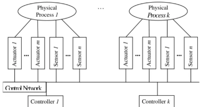
Fieldbus networks are becoming increasingly popular in computer-controlled systems. Fieldbus allow field devices like sensors, actuators and controllers to be interconnected at low cost, using less wiring and requiring less maintenance than point-to-point connections. Besides the economical aspects, the use of Fieldbus in computer-controlled systems is also reinforced by the increasing decentralization of control and measurement tasks. Computer-controlled systems wherein the control loops are closed through a real-time fieldbus network are called Network Controlled Systems (NCS) (Figure 1).
Control Network
Figure 1: Example of a Network Controlled System (NCS)
Max Mauro Dias Santos1,Marcelo Ricardo Stemmer2 and Francisco Vasques3
1 UnilesteMG, CEP 35170-056, Coronel Fabriciano – MG – Brasil. e-mail: [email protected] 2 Universidade Federal de Santa Catarina, 88040-900, Florianópolis – SC – Brasil. e-mail: [email protected]
3 Faculdade de Engenharia da Universidade do Porto - 4200-465, Porto – Portugal. e-mail: [email protected]
ANALYSIS OF TIMING PROPERTIES FROM
NETWORK CONTROL SYSTEMS
The assessment of the control network must be made considering its capability to provide a real-time service to the supported control applications. A widely used network, usually considered suitable to support small-scale NCS, is CAN.
Controller Area Network (CAN) [1] was originally designed for use within road vehicles, to solve cabling problems arising from the growing use of microprocessor-based components in vehicles. Due to its very interesting characteristics, CAN is also being considered for manufacturing environments [2], and is being used as the communication interface in proprietary architectures, such as DeviceNet [3], which target small-scale NCS. Several studies on how to guarantee the timing requirements of messages in CAN networks are available (e.g. [4]), thus providing pre-run-time schedulability conditions for the analysis of the timing requirements of NCS traffic.
Using a control network to interconnect sensors, actuators and controllers in a feedback control system, requires the use of a control network that must be simultaneously:
a) able to support periodic message streams, in order to convey the control-related periodic data between the controller and the set of related sensors / actuators;
b) able to guarantee upper-bounded response times for the message transfers, in order to cope with the control-related delays;
c) and, above all, able to guarantee a predictable timing behaviour in the presence of a variable network load due to traffic non related to the control application (such as: alarms, surveillance video streams, etc.).
That is, the control network must provide a real-time service to the supported applications.
In addition, a well-known problem when using a control network is the presence of induced
jitter, that is, the variability of the time interval between consecutive transfers.
For instance, in spite of periodically requesting the transfer of a specific sensor value, the actual transfer will not be immediately executed, as messages need to be scheduled for transmission in a shared resource (the communication medium). As a consequence, in some cycles the sensor message will be transferred earlier in the cycle period, and in some other cycles it will be transferred later. The real-time service provided by the control network will just guarantee that the sensor message will always be transferred before its deadline.
The jitter problem can be even more acute, when the control network is shared between multiple control loops (Figure 2). In such case, a particular sensor requesting to transfer its data, may immediately transfer it, or may have its request scheduled with multiple other requests (and thus, the transfer of the sensor data will be postponed). The larger the number of messages requesting to be simultaneously transferred, the larger will be the induced jitter.
... Controller 1 A ct ua to r 1 A ct ua to r m ... Se ns or 1 Se ns or n Physical Process 1 ... Controller k A ct ua to r 1 A ct ua to r m ... Se ns or 1 Se ns or n Physical Process k ... Control Network
The remainder of this paper is organized as follows. Section II describes the most important characteristics of CAN network. Particular relevance is given to their MAC protocols, as these are fundamental for the response time analysis performed in Section III. In Section IV, the jitter problem is addressed for the case of a Network Controlled System. Mainly, we characterize the jitter in terms of real-time parameters. Then, in Section V, we analyse by means of simulation the behaviour of the CAN protocol for both the cases of single and multiple control loops. Finally, in Section VI some conclusions are drawn.
II. MAINCHARACTERISTICSOFCANPROTOCOL
A. CAN Protocol
The CAN protocol implements a priority-based bus, with a carrier sense multiple access with collision avoidance (CSMA/CA) MAC. In this protocol, any station can access the bus when it becomes idle. However, contrarily to Ethernet-like networks, the collision resolution is non-destructive, in the sense that one of the messages being transmitted will succeed.
There are 4 types of frames that can be transferred in a CAN network. Two of them are used during the normal operation of the CAN network: the Data Frame, which is used to transfer data from one station to another and the Remote Frame, which is used to request data from a distant station. The other two frames are used to signal an abnormal state of the CAN network: the Error Frame signals the existence of an error state and the Overload Frame signals that a particular station is still not ready to transmit data.
Bus signals can take two different states: recessive bits (idle bus), and dominant bits (which always overwrite recessive bits). The collision resolution mechanism works as follows: when the bus becomes idle, every station with pending messages will start to transmit. During the transmission of the identifier field, if a station transmitting a recessive bit reads a dominant one, it means that there was a collision with at least one higher-priority message, and consequently this station aborts the message transmission. The highest-priority message being transmitted will proceed without perceiving any collision, and thus will be successfully transmitted. The highest priority message is the one with most leading dominant bits on the identifier field. Obviously, each message stream must be uniquely identified. The station that lost the arbitration phase will automatically retry the transmission of its message.
III. RESPONSETIMEANALYSISINCANANDPROFIBUSPROTOCOLS
A. Network and Message Models
We assume a network with p stations and n message streams defined as: ) , , ( i i i i C T D S = (1)
A message stream is a temporal sequence of messages concerning, for instance, the remote reading of a specific process variable. For the CAN case, a message stream i is characterized by a
unique identifier. Ci is the longest message duration of stream Si. Ti is the periodicity of stream Si
requests, considered as the minimum time interval between two consecutive arrivals of Si requests
to the outgoing queue. Finally, Di is the relative deadline of a message; that is, the maximum
admissible time interval between the instant when the message request is placed in the outgoing queue and the instant when either the message is completely transmitted.
B. Response Time Analysis of CAN Networks
In [4] the authors addressed in detail the response time analysis of CAN networks. They assumed fixed priorities for message streams (since the network access is based on the identifier’s priority and the message model assumes that each message stream has its own unique identifier) and a non-preemptive scheduling model (since lower priority messages being transmitted cannot be pre-empted by pending higher priority messages). Considering such scheduling model, they adapted all the existing schedulability analysis for task scheduling [8] to the case of scheduling messages on a CAN network.
The worst-case response time of a queued message, measured from the arrival of the message request to the outgoing queue to the time the message is fully transmitted, is:
m m
m I C
R = + (2)
To guarantee that the system is schedulable it is sufficient to verify if every message has a response time smaller than its deadline. The term Im represents the worst-case queuing delay -
longest time interval between placing the message in the outgoing queue and the start of the message transmission.
The deadline monotonic (DM) priority assignment [8] can be directly implemented in a CAN network, by setting the identifier field of each message stream according to the DM rule. Therefore, the worst-case queuing delay of message m is:
( )
∑
∈ ∀ × + + = m hp j j j bit m m m T C I B I τ (3)where Bm is the worst-case blocking factor, which is equal to the longest duration of a lower
priority message, and is given by:
( )m
{ }
k lp k m C B max 0, ∈ ∀ = (4)The set lp(m) is the set of message streams with lower-priority than message stream Sm. τbit is the
duration of a bit transmission and hp(m) is the set of message streams in the system with higher-priority than the message stream Sm. equation (3) embodies a mutual dependency, since Im appears
in both sides of the equation. In fact all the analysis underlay this mutual dependence, since in order to evaluate Rm, Im must be found and vice-versa. The easiest way to solve such equation is to
IV. JITTERANALYSIS
A. Control Execution Delay
In a traditional Computer-Controlled System, sensors and actuators are connected to the controller by means of point-to-point connections. Therefore, the controller system will sample the input signals every hk time intervals, by directly reading each sensor value at a local ADC (Analog
to Digital Converter). Conversely, after executing the control algorithm, the controller will update each actuator by directly writing the related value at a local DAC (Analog to Digital Converter). Therefore, the control execution delay is τk, which must include the ADC/DAC conversion delays
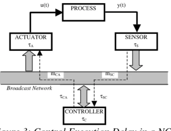
When considering a Network Controlled System (NCS), as the IO devices are connected to the controller node by means of a broadcast network, the read/write interactions between the controller and sensors/actuators nodes will be made through the exchange of control message’s (Figure 3).
Broadcast Network mSC mCA PROCESS ACTUATOR τA SENSOR τS CONTROLLER τC u(t) y(t) τSC τCA Figure 3: Control Execution Delay in a NCS
Therefore, when considering a NCS, the delay between sampling a sensor value and updating the related actuator value must consider not only the execution time of the controller algorithm and the ADC/DAC conversion delays, but also the delays associated to the communication network. That is, the node processing delay and the communication delay, which includes the medium access (message scheduling) and the message transmission delays. The control execution delay will then be: k a k ca k c k sc k s k τ τ τ τ τ τ = + + + + (6) B. Task Characterization
Concerning the triggering characteristics of the several tasks, the sensor task should be a
time-triggered periodic task, which samples the process and sends the sampling value to the controller
node. The processing delay at the sensor node, which includes both the ADC conversion and queuing the message in the transmission queue, is: τsk.
The controller task should be an event-triggered task (i.e. an interrupt-driven task), triggered by the arrival of the related sensor value. The processing delay of this task: τck, includes both the
interrupt dispatching delay and processing delay of the control algorithm.
The actuator task should be also an event-triggered task, triggered by the arrival from the controller node of the related actuation value. The processing delay of this task: τak, includes both
the interrupt dispatching and the DAC conversion delays.
C. Communication Delay
Finally, the network communication delay includes both the medium access (message scheduling) and the message transmission delays. However, while the message transmission delay is approximately constant, the medium access delay is highly variable as it depends on the instantaneous network load and it also depends on the medium access protocol. Therefore, these communication delays (τsck and τack) must be carefully evaluated in order to characterize the NCS
behaviour.
The variation of such communication delay imposes a timing variation to the control execution delay, which is defined as control jitter. Such control jitter has a strong influence on the stability and the performance of the Network Controlled System.
Two optional approaches can be used to characterize such communication delays:
a) Either assuming the maximum response time analysis, which guarantees that control messages will never be delayed more than a specific upper-bound delay. Equations (2) and (5) can be used for the evaluation of the maximum response time of messages using the CAN protocol. b) Or, assuming that simulation results are enough to assess the stability and performance
properties of the underlying Network Controlled System.
V. BEHAVIOUR OF A NETWORK CONTROLLED SYSTEM USING THE CANPROTOCOL
In this Section we analyse by means of simulation the behaviour of a Network Controlled System, when the underlying control network is based on the CAN communication protocol. Firstly, we present the dynamic model for a small DC servomotor, based on the model presented in [10] and we will define the related set of message streams that must be supported by the communication network. Then, we assess the capability of the CAN network to support the position and velocity control of such servomotor.
A. Servomotor Model
Consider the small DC servomotor model presented in [10], where the control target is that the servomotor position y(t) follows an input reference signal u(t). The transfer function of such DC servomotor is:
( ) ( )
1 1000 + = s s s G (7)A PD controller (proportional plus derivative actions), implemented as a discrete controller with the following parameters: K=1.5 and Td=0.035, controls the servomotor. A sampling interval hk
guaranteeing the thumb rule of 0.2 < ωb×hk < 0.6 has been chosen, where ωb is the bandwidth of
the closed loop system. In the design phase, it has been defined a bandwidth of ωb = 80rad/s
(approximately 500Hz), with a sampling interval of 10ms.
B. Message Stream Set
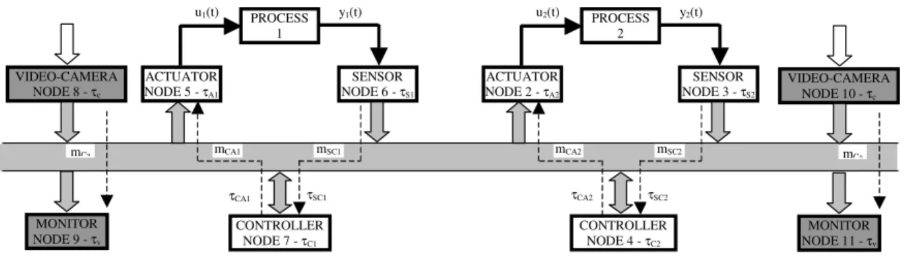
We consider that the CAN network is supporting two similar Network Controlled Systems (DC Servomotors controlled by PD controllers) executing each one at a sampling rate of 100Hz, plus two video message streams with bandwidths of, respectively, 400 and 333 kbps (Figure 4).
mSC2 mCA2 mSC1 mCA1 PROCESS 1 ACTUATOR NODE 5 - τA1 SENSOR NODE 6 - τS1 CONTROLLER NODE 7 - τC1 u1(t) y1(t) τSC1 τCA1 PROCESS 2 ACTUATOR NODE 2 - τA2 SENSOR NODE 3 - τS2 CONTROLLER NODE 4 - τC2 u2(t) y2(t) τSC2 τCA2 VIDEO-CAMERA NODE 8 - τc MONITOR NODE 9 - τv mCa VIDEO-CAMERA NODE 10 - τc MONITOR NODE 11 - τv mCa
Figure 4: Network Controlled Systems under Analysis
CAN Network– 1 Mbps
Case 1 Case 2 Case 3
Message Stream Message length Ci (ms) Message periodicit y Ti (ms) Bus Utilizatio n (%) Stream Priorit y Message Resp. Time Ri (ms) Stream Priorit y Message Resp. Time Ri (ms) Stream Priorit y Message Resp. Time Ri (ms) mSC1 (sensor to controller 1) 0,1 10 1 1 0,2 1 0,2 1 0,2 mSC2 (sensor to controller 2) 0,1 10 1 2 0,3 3 0,4 5 8,4
mCA1 (controller to actuator
1) 0,1 10 1 3 0,4 2 0,3 2 0,3
mCA2 (controller to actuator
2) 0,1 10 1 4 0,5 4 0,5 6 8,5
Video stream mC1 8×0,1 2 40 5 1,3 5 1,3 3 1,1
Video stream mC2 10×0,1 3 33,3 6 2,3 6 2,3 4 2,1
Table 1: Message Stream Set Characterization
The time characteristics of the related message streams are represented in Table 1. For each message stream is defined its message length and periodicity. The video message streams are characterised for sending each one, respectively, 8 and 10 messages per activation. The resulting bus utilization for each message stream indicates an overall network load of 77,3%.
Two video message streams impose a well-defined network load pattern, which will, in some cases, interfere with the control-related traffic. Three different cases are analysed for the control-related messages:
1. The higher priorities (1-2) are assigned to the sensor-sampling messages, then the intermediate priorities (3-4) are assigned to the actuator-writing messages and, finally, the lowest priorities (5-6) are assigned to both video streams;
2. The higher priorities (1-2) are assigned to process-1 messages, then the intermediate priorities (3-4) are assigned to process-2 messages and, finally, the lowest priorities (5-6) are assigned to both video streams;
3. Finally, the higher priorities (1-2) are assigned to process-1 messages, then the intermediate priorities (3-4) are assigned to both video streams and, finally, the lowest priorities (5-6) are assigned to process-2 messages;
The resulting message response times are evaluated for each one of the three cases, using equation (2). The shadowed cases represent the communication delays (τsck and τack) for processes 1 and 2, which
is the most important part of the control execution delay (6).
C. Simulation Results
The target of these simulations is to analyse the behaviour of a Network Controlled System, when the underlying control network is the CAN network. Specifically, the target is to assess the behaviour of the supported applications when considering different priority assignment schemes to the control-related messages. The presented simulations are made using the TrueTime toolbox [10].
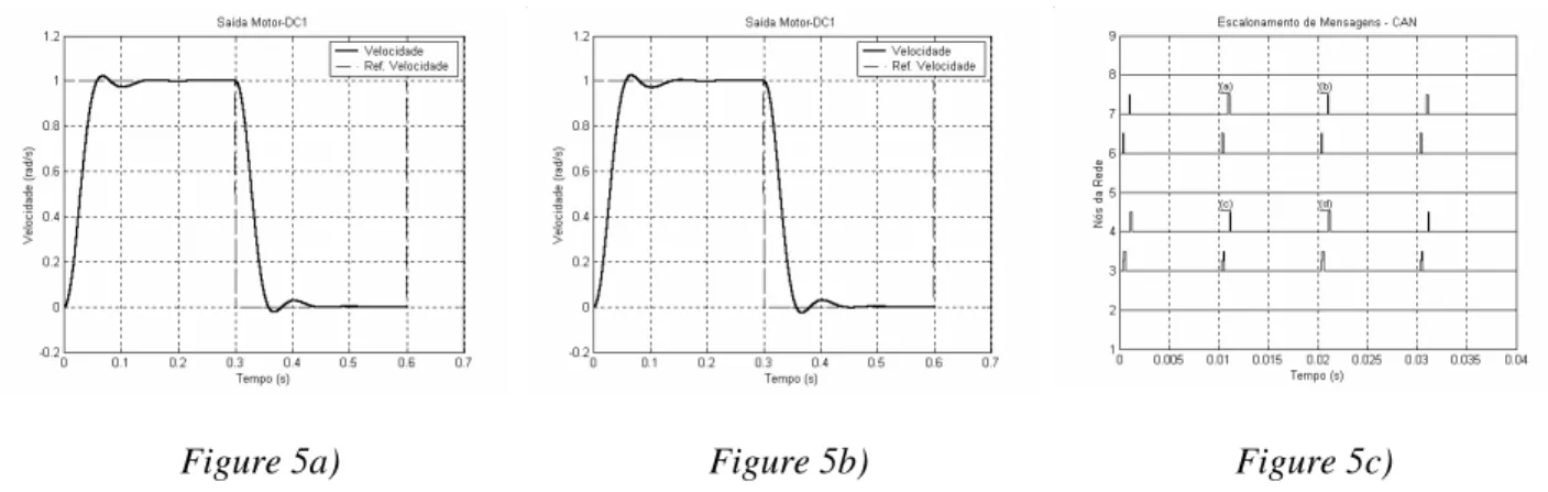
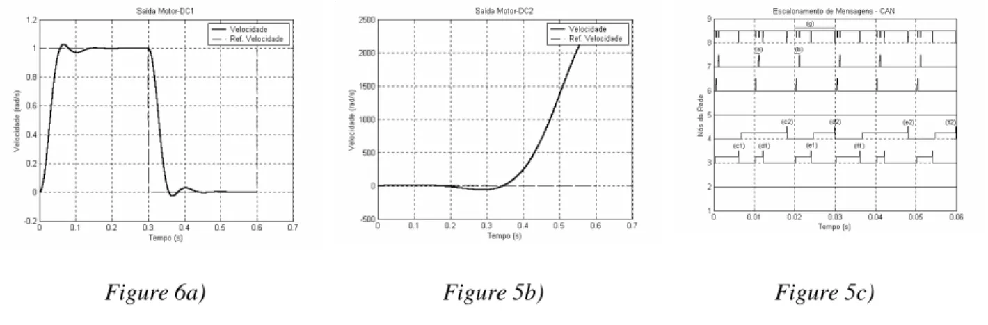
The simulation results for case 1 and 2 are represented in Figure 5: Figures 5a) and 5b) indicates an almost equivalent velocity step response for motor 1, which was the expected result as the communication delay for both cases is equivalent (0,3ms vs. 0,4ms in the worst-case, when compared to a sampling interval of 10ms). The results for motor 2 are not represented.
Figure 5a) Figure 5b) Figure 5c)
The resulting message scheduling is shown in Figure 5c), where it is clear the delay imposed to the message transfer (a and b represent τca1, while c and d represent τca2), are considerably smaller than the
Figure 6a) Figure 5b) Figure 5c)
The simulation results for case 3 are represented in Figure 6, where the communication delay associated to the motor 2 is considerably longer than that of motor 1 (shadowed cases of Table 1). Therefore, while the velocity step response for motor 1 (Figure 6a) is equivalent to the previous cases, the response for motor 2 (Figure 6b) is no longer acceptable.
Finally, in Figure 6c) it is represented the resulting message scheduling, where it is clear that the communication delay imposed to messages related to motor 2 is considerably longer than the delay imposed to messages related to motor 1 (a and b represent τca1, while c and d represent τca2).
VI. CONCLUSIONS
One of the problems that must be adequately considered when implementing a Network Controlled System (NCS) is the message jitter. This message jitter, as it is embedded within the control loop, will have a strong impact on the control execution delay.
In this paper, we briefly compare the timing properties of both CAN and PROFIBUS control networks. Then, using a small example of a NCS, we assess the capability of the CAN network to fulfil control application requirements.
REFERENCES
[1] ISO 11898 (1993). Road Vehicle - Interchange of Digital Information - Controller Area Network (CAN) for High-Speed Communication. ISO.
[2] Zuberi, K. and Shin, K. (1997). Scheduling messages on Controller Area Network for Real-Time CIM Applications. In IEEE Transactions on Robotics and Automation, Vol. 13, No. 2, pp 310-314. [3] Rockwell Automation. (1997). DeviceNet Product Overview. Publication DN-2.5, Rockwell. [4] Tindell, K., Burns, A. and Wellings, A. (1995). Calculating Controller Area Network (CAN)
Message Response Time. In Control Engineering Practice, Vol. 3, No. 8, pp. 1163-1169.
[5] Grow, R. (1982). A Timed Token Protocol for Local Area Networks. In Proc. of Electro’82, Token Access Protocols, Paper 17/3.
[6] Audsley, N., Burns, A., Richardson, M., Tindell, K and Wellings, A. (1993). Applying New Scheduling Theory to Static Priority Pre-emptive Scheduling. In Software Engineering Journal, Vol. 8, No. 5, pp. 285-292.
[7] Cervin, A., Henriksson, D., Lincoln, B. and Arzén, K. E.(2003). Analysis and Simulation of Controller Timing. To Appear in Control Systems Magazine, 2003.