Paulo Filipe de Jesus Cruz
Development of an environment for the
generation, mutation and execution of test
cases
Dissertação de Mestrado
Paulo Filipe de Jesus Cruz
Development of an environment for the
generation, mutation and execution of test
cases
Mestrado em Engenharia Informática
Trabalho realizado sob orientação de
Professor José Creissac Campos
A special thanks to my family that supported me, to my friends who helped me when I needed it, especially those who did not understand anything I said, but listened anyway, and to my supervisor for the opportunity and for being always available to clarify doubts and help me developing this project.
This work was funded by FEDER funds through the Programa Operacional Factores de Competitividade- COMPETE and National Funds through FCT – Fundação para a Ciência e Tecnologia under the project FCOMP-01-0124-FEDER-020554. The work of the author was also supported by a grant with reference PTDC/EIAEIA/119479/2010_UMINHO.
ABSTRACT
Development of an environment for the generation, mutation and
execution of test cases
Testing graphic user interfaces (GUI) involves, mainly, lengthy and expensive processes involving user testing. Finding simpler and easier alternatives to use than these processes becomes an exciting proposal. This project presents an alternative to existing processes through the use of Model-based Testing - MBT.
The MBT technique takes advantage of models that describe the correct operation of the system (for this project task models). The use of MBT may thus become a new approach to testing GUI's, since the implemented GUI is tested against the model that specifies it the correct behavior. All inconsistencies found during the tests will be treated as potential errors that must be corrected.
This report describes the development of a prototype for an environment able to generate and execute test cases applying MBT to GUI's.
Key words: Model-based testing, Graphic User Interfaces, Task Models, Application areas: Web interfaces
RESUMO
Desenvolvimento de um ambiente para a geração, mutação e execução
de casos de teste
A realização de testes a interfaces gráficas (GUI) envolve, maioritariamente, processos morosos e dispendiosos. Encontrar alternativas mais simples e fáceis de utilizar do que estes processos torna-se uma proposta aliciante. Este projeto apresenta uma solução alternativa aos processos já existentes através da utilização de casos de teste baseados em modelos (Model-based Testing - MBT).
Esta técnica tira partido de modelos que descrevem o correto funcionamento do sistema (no caso particular do projecto modelos de tarefas). A utilização do MBT pode assim transformar-se numa nova abordagem aos testes realizados sobre GUI’s, uma vez que a GUI implementada será testada contra o modelo especificado que contém o funcionamento correto desta. As incoerências encontradas nos testes apontam para potenciais erros que deverão ser corrigidos.
Este relatório descreve o desenvolvimento de um protótipo para um ambiente capaz de gerar, mutar e executar casos de teste para GUI’s aplicando o MBT.
Palavras-chave: Testes baseados em modelos, interfaces gráficas, modelos de tarefas Área de Aplicação: interfaces gráficas Web
CONTENTS
ABSTRACT III RESUMO IV CONTENTS V LIST OF FIGURES IX LIST OF TABLES XIGLOSSARY AND ACRONYMS XII
1. INTRODUCTION 1
1.1 BACKGROUND 1
1.2 PROJECT DESCRIPTION 3
1.3 REPORT STRUCTURE 4
2. SOFTWARE TESTING 5
2.1 SOFTWARE TESTING LIFE CYCLE 6
2.2 TESTING LEVELS 7
2.2.1 TESTING TARGET 7
2.2.2 TESTING OBJECTIVES 8
2.3 TESTING METHODS 11
2.4 MODEL-BASED TESTING 12
3. GUI MODEL-BASED TESTING 15
3.1 APPLYING MBT TO GUI’S 16
3.1.1 TASK MODELING TOOLS 16
3.1.2 TEST CASES AUTOMATION TOOLS 17
3.2 CONCLUSION 19
4. IMPLEMENTATION AND DEVELOPMENT 20
4.1 PROPOSED APPROACH 20
4.2 TASK MODELS WITH CTT(CONCURRTASKTREE) 22
4.3 TEST CASES 25
4.3.1 TEST CASES CONFIGURATION 25
4.3.2 TEST CASES GENERATION 29
4.4 TEST CASES MUTATION 32
4.5 TEST CASES EXECUTION 33
4.6 CONCLUSION 37
5. TESTING USER INTERFACES 38
5.1 TAPPORTUGAL –SEARCH FLIGHTS AND HOTELS 38
5.1.1 TASK MODEL 38
5.1.2 CONFIGURATION FILES 40
5.1.3 TEST CASES 41
5.1.4 TEST CASES EXECUTION 43
5.1.5 MUTATED TEST CASES 45
5.1.6 MUTATED TEST CASES EXECUTION 46
5.2 MICROSOFT OUTLOOK (ONLINE) 48
5.2.1 TASK MODEL 48
5.2.3 TEST CASES 51
5.2.4 TEST CASES EXECUTION 53
5.2.5 MUTATED TEST CASES 54
5.2.6 MUTATED TEST CASES EXECUTION 55
5.3 CONCLUSION 57
6. CONCLUSIONS 58
6.1 OBJECTIVES ACHIEVED AND LIMITATIONS 58
6.2 FUTURE WORK 59
REFERENCES 60
APPENDIXES 62
I. TAP CASE STUDY 62
Task Model 62
Generated Code Example 63
II. MICROSOFT OUTLOOK CASE STUDY 73
Task Model 73
Generated Code Example 74
III. UNUSED TERESA OPERATORS 84
Operator: Optional Task 84
Operator: Iterative task 87
Operator: Order Independence 88
Operator: Concurrent with Info Exchange 91
LIST OF FIGURES
FIGURE 1 - STLC STAGES AND PERFORMED ORDER (ADAPTED FROM [9]) ... 6
FIGURE 2 - V-MODEL (ADAPTED FROM [12]) ... 10
FIGURE 3 - MODEL-BASED TESTING PROCESS (ADAPTED FROM [12]) ... 14
FIGURE 4 - PROCESS OF GENERATING AND EXECUTING TEST CASES ... 21
FIGURE 5 - SEARCHING ALPHA AND INTERCITY TRAINS IN CP WEB PAGE ... 21
FIGURE 6 – ALFA AND INTERCITY TRAINS SEARCH IN CP ... 25
FIGURE 7 - MAPPING FILE STRUCTURE ... 26
FIGURE 8 - TEST CASES CONFIGURATION FILE STRUCTURE ... 26
FIGURE 9 - EXAMPLE OF FILLING THE CONFIGURATION FILES ... 27
FIGURE 10 - PATH FOUND FOR THE CP EXAMPLE ... 30
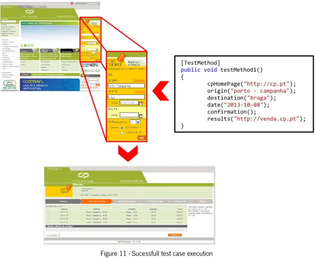
FIGURE 11 - SUCESSFULL TEST CASE EXECUTION ... 34
FIGURE 12 - TEST RESULTS PRESENTED IN VISUAL STUDIO 2010 ... 35
FIGURE 13 - GENERATED LOG FILE FOR THE EXECUTED TEST CASE ... 36
FIGURE 14 - GENERATED GRPAH FOR THE TEST CASE ... 36
FIGURE 15 - SEARCH FOR FLIGHTS (ONE WAY ONLY) IN TAP WEB PAGE ... 39
FIGURE 16 - TAP TASK MODEL SAMPLE ... 39
FIGURE 17 - MAPPING THE INTERFACE INTO THE TASK MODEL ... 40
FIGURE 18 - CONFIGURATION FILES FOR THE ONLY ONE WAY FLIGHTS ... 41
FIGURE 19 - PATHS FOUND FOR TAP TASK MODEL... 42
FIGURE 20 - TAP TEST CASE EXECUTION EXAMPLE ... 44
FIGURE 21 - TEST RESULTS PRESENTED IN VISUAL STUDIO 2010 ... 45
FIGURE 22 - GENERATED LOG FILE ... 45
FIGURE 23 - EXEMPLE OF AN EXECUTION OF A MUTATED TEST CASE... 47
FIGURE 24 - TEST RESULTS SHOWN IN THE VISUAL STUDIO FOR A MUTATED TEST ... 47
FIGURE 25 - LOG FILE GENERATED FOR THE MUTATED TEST CASE EXECUTED ... 48
FIGURE 26 - OUTLOOK TASK MODEL SAMPLE (SEND AN EMAIL) ... 49
FIGURE 27 - SENDING AN EMAIL IN OUTLOOK ... 49
FIGURE 28 - MAPPING BETWEEN THE INTERFACE AND THE OUTLOOK TASK MODEL ... 50
FIGURE 29 - CONFIGURATION FILES FOR SEND EMAIL OPTION ... 50
FIGURE 30 - EXAMPLE OF PATHS FOUND FOR OUTLOOK TASK MODEL ... 51
FIGURE 32 - TEST RESULTS PRESENTED IN VISUAL STUDIO 2010 ... 54
FIGURE 33 - GENERATED LOG FILE ... 54
FIGURE 34 - EXAMPLE OF AN EXECUTION OF A MUTATED TEST CASE ... 56
FIGURE 35 - TEST RESULTS SHOWN IN THE VISUAL STUDIO FOR A MUTATED TEST ... 56
FIGURE 36 - LOG FILE GENERATED FOR THE MUTATED TEST CASE EXECUTED ... 57
LIST 1 - CODE SNIPPET FOR TRAINS SEARCH IN CP ... 31
LIST 2 - MUTATED TEST CASES GENERATED FOR EACH TYPE OF MUTATION IDENTIFIED ... 33
LIST 3 - GENERATED TEST CASES FOR TAP TASK MODEL ... 43
LIST 4 - EXAMPLES OF MUTATED TEST CASES FOR TAP TASK MODEL ... 46
LIST 5 - EXAMPLE OF TEST CASES GENERATED ... 53
LIST OF TABLES
TABLE 1 - SOFTWARE TESTING LIFE CYCLE PHASES (ADAPTED FROM [10]) 7
TABLE 2 - TYPE OF TASKS 22
TABLE 3 - CTT OPERATORS 23
TABLE 4 – KEYORDS DEFINED 24
TABLE 5 - CORRESPONDENCES BETWEEN THE HTML ELEMENTS AND WATIN CLASSES 28 TABLE 6 - CORRESPONDENCES BETWEEN THE HTML ELEMENTS AND WATIN CLASSES
GLOSSARY AND ACRONYMS
AGILE Methodology that promote the planning, development and delivery of a software product.
CTT ConcurrTaskTrees
GUI Graphic User Interface
MBT Model-based Testing
ORACLE Model from a software system
STLC Software Testing Life Cycle
SUT System Unter Test
TASK NOTATION Hierarchical decomposition into sub-tasks that must be done to achieve an objective.
HTML HyperText Markup Language. A language for creating web pages and other information that can be displayed in a web browser
1. INTRODUCTION
This report and the project to which it refers were carried out for the Dissertation of the 2nd year of the Master's Degree in Informatics Engineering of the Department of Informatics, School of Engineering, University of Minho. The project is also associated with HasLab (High-Assurance Software Laboratory), INESC TEC.
1.1 Background
What is software quality? The definition of software quality is not that simple since a software product has a lot of characteristics that can be considered crucial. The quality of a software artifact can be understood as the totality of characteristics of the system, component or process that affect its ability to satisfy stated or implied needs (requirements or customer/user needs) [1].
The quality of user interfaces (from the point of view of the user) can be seen as its usability. The principles of usability are described in ISO 9241-11 [2]. A graphical user interface that respects the principles of usability will allow users to achieve their goals with effectiveness (accuracy and completeness with which these goals can be achieved), efficiency (level of effort required) and satisfaction, in a particular context of use (subjective rating on criteria such as discomfort experienced, liking for the product, satisfaction with product use, or acceptability of the workload when carrying out different tasks).
These days, Graphical User Interface (GUI) are a key point for communication between user and system and this means that tests must be performed on the interface layer to guarantee its proper functioning. Software testing is very important to ensure the quality of the developed system. When we put a system under test the main goal is to find software bugs,
errors or inconsistencies in the functionalities that were implemented. Normally, the test effort is performed after the requirements (of the system) are fully defined and the coding process almost or completely finished. However with the adoption of AGILE 1 software development methodologies the testing effort tends to follow the development of the system [3]. It is also important to note that software testing involves considerable costs in terms of time and money. Fortunately, there are several techniques to perform tests on a software system that help to minimize these costs. The chosen one for this project in particular was Model-based Testing.
Model-based testing (MBT) techniques offer the possibility of automating the testing process by making a comparison between the model of a software system (the oracle) and the implemented version of the same system. Techniques such as MBT, by making use of models to analyse the running system, are concrete examples that “modeling is a simple way of capturing
knowledge about the system and then reutilizing this knowledge as the system grows” [4]. In the context of this project a model of a software system can be seen as a description of its behavior. The inputs accepted by the interface, the outputs it generates, and the control logic behind them. Several authors have explored the use of models, trying to find a simple and economic
way for testing the interface layer of a software system [5, 6]. The possibility of exploring task models for the generation of oracles has also been studied [7]. These techniques were developed in order to improve the quality of generated test cases, but since a task model only considers the expected behavior of the user, the latter study explores modifications to the oracle to be able to detect problems that may occur due usage errors in the interface layer. That work, however, is still preliminary.
1An AGILE methodology promote the planning, development and delivery of a software product in a time-boxed
The current project arises from the need to create a tool capable of generating and executing test cases in order to test the behavior of web applications. To simulate a scenario in which the user makes mistakes, the possibility of creating mutations on the generated test cases will also be explored.
1.2 Project Description
The work was developed under a research grant from the “PBGT – Pattern Based GUI Testing” project. This project aims to carry out research on the development and validation of test strategies based on models applied to interfaces. It is important to develop an environment for the generation, mutation and execution of test cases able to fulfill this objective. The developed environment must automate the testing process applied to graphical interfaces.
This project aims to develop a tool capable of generating and executing test cases, as well as mutating these test cases in order to test the behavior of the application in case of operating errors. Thus we can improve the ability to detect errors of this kind of technique and increase the quality assurance that the technique allows.
Given that graphical user interfaces are the key point of computer systems these days and that the use of the Web had a tremendous growth, the creation of applications that can generate test cases starting from the specification of the graphic interface (task models, in the case of this project) makes a time consuming process, as the generation of different test cases, a simple task with little effort by the software tester. This work brings a new use to already existing tools and frameworks with the objective to create a standard in the test case automation for the web.
1.3 Report Structure
This report is constituted by six chapters as described:
Chapter 1 – Introduction: This chapter has presented the background of the project as well as the problem to solve.
Chapter 2 – Software Testing: This chapter presents the background needed to understand the concepts used during the project.
Chapter 3 – GUI based Testing: This chapter justifies the use of Model-based testing as well as presenting tools that can help in the application of MBT.
Chapter 4 – Implementation and Devepment: This chapter presents the proposed approach to resolve the problem presented in Chapter 1 as well as the implemented solution.
Chapter 5 – Case Studies: This chapter presents the examples created using the developed tool.
Chapter 6 – Conclusions: This chapter describes all the work done by referencing the objectives achieved and how they can be improved in the future.
2. SOFTWARE TESTING
Computers are nowadays a key player in business, education or recreational activities, responsible for the creation of millions of jobs around the world. This makes it necessary to ensure that the applications they run actually perform the tasks for which they were designed. The “software should be predictable and consistent, offering no surprises to users” [8]. To guarantee that these software applications carry out their functions properly and do not perform actions that should not occur it is necessary to perform tests.
Software testing can be seen as an investigation that provides objective information on the quality of the product. It can also be understood as an independent view of the software, or as a process of validating a software product, in which it must be verified if the implemented software meets the requirements that guided its design and development. If it works as expected and if satisfies the needs of stakeholders.
With the adoption of AGILE software development methodologies the testing effort tends to follow the development of the system, because testing is not a simple activity and must be included in the development and maintenance of the software product. Developing a software system always implies risks and a problem if identified too late may involve too many costs in its resolution. One of the objectives of testing software is to identify errors, software bugs or faults, and the sooner the better. But even a tested software product is not 100% free of errors. Because testing is an expensive process, it is not always possible to test every aspect of the product. The problems not found will increase the software maintenance costs.
2.1 Software Testing Life Cycle
Considering software testing as an iterative process several phases can be identified in which different tasks are performed. These different phases together form the Software Testing Life Cycle – STLC (see Figure 1). These phases cover the whole process of testing a system, from identifying requirements and planning the tests, through to executing them and reporting the results.
Figure 1 - STLC stages and performed order (adapted from [9])
Different techniques are associated to each phase of the STLC, these activities and the associated phase can be viewed in the Table 1. The left column lists the phases identified in Figure 1, and the right column the relevant activities for each phase.
Software engineers must be aware that there are also many methods for testing a software system (described in section 2.3). Even a simple program can generate, theoretically, an infinite set of tests. This means that selecting tests can be a difficult task. Testing a software product will require the identification of which values are acceptable as input and output, which sometimes is not possible. The software engineer must also be able to identify if the observed behavior is consistent with the expected performance.
PHASE ACTIVITIES
Requirements Analysis/ Design Review
Review the software requirements/design (if they already exists)
Interaction with stakeholders
Understand the requirements in detail
Test Planning
Plan the test once gathered the general idea of what need to be tested
Determine cost estimated for tests
Test Designing Creation, verification, validation and rework of test
cases and test scripts
Test Environment Setup
Decide the software and hardware conditions under which the product will be tested (replicate the end-users’ environment)
Test Execution Execute the test scripts in the test environment and
verify if they pass
Test Reporting Analyze testing artifacts and present them to the
stakeholders
Table 1 - Software Testing Life Cycle phases (adapted from [10])
2.2 Testing Levels
2.2.1 Testing Target
“Software testing is usually performed at different levels along the development and maintenance process” [1] this means that the test target can vary. Test can be executed in a single module, a group of modules (related to each other) or the entire system.
The levels defined in the Software Engineering Body of Knowledge [1] are Unit-, Integration-, and System Testing. They are distinguished by the target that they are associated with.
Unit testing refers to tests that verify the functionality of a specific software piece, which is tested separately from the rest of the system. Depending of the context unit tests can be performed in a single module or in a specific program function. Usually, unit testing needs access to the code that will be tested and support of debugging tools.
Integration testing is used to verify the interfaces between software components. Usually it is tested if the different components are properly integrated with each other. Integration testing is an ongoing activity. In each phase of development of the product the software engineers should only focusing on the level they are integrating and disregard the lower-levels (which already have been integrated) [1].
System testing like the name implies tests a completely integrated system to verify that it meets its requirements. At this stage of testing the majority of functional malfunctions should been already identified and resolved in unit and integration testing levels.
2.2.2 Testing Objectives
Tests can be conducted taking into account different objectives. Testing efforts can be aimed at verifying if functional specifications are properly implemented, but several nonfunctional properties of the system can be tested as well.
Depending on the objectives to be achieved with the tests, different levels of testing were identified by A. Abran et al [1].
Acceptance/Qualification testing: Acceptance testing verifies the system behavior
against the customer’s requirements.
Installation testing: After accomplishment of system and acceptance testing, the software can be verified upon installation in the target environment.
Alpha and beta testing: Before the software is released, it is given to a small representative set of potential users for trial use, either in-house (alpha testing) or external (beta testing), which report problems with the product.
Conformance testing/ Functional testing/ Correctness testing: Validating whether or not the observed behavior of the tested software conforms to its specifications.
Reliability achievement and evaluation: In helping to identify faults, testing is a means to improve reliability. By contrast, by randomly generating test cases according to the operational profile, statistical measures of reliability can be derived.
Regression testing: According to IEEE610.12-90 [11], regression testing is the “selective retesting of a system or component to verify that modifications have not caused unintended effects”.
Performance testing: Verify that the software meets the specified performance requirements, for instance, capacity and response time.
Stress testing: Stress testing exercises software at the maximum design load, as well as beyond it.
Back-to-back testing: A single test set is performed on two implemented versions of a software product, and the results are compared.
Recovery testing: Recovery testing is aimed at verifying software restart capabilities after a “disaster.”
Configuration testing: In cases where software is built to serve different users, configuration testing analyzes the software under the various specified configurations.
Usability testing: This process evaluates how easy it is for end-users to use and learn the software, including user documentation.
Test-driven development: Test-driven development is not a test technique per se, promoting the use of tests as a surrogate for a requirements specification document rather than as an independent check that the software has correctly implemented the requirements.
In practical terms tests are typically conducted at four main levels Unit-, Integration-, System- and Acceptance Testing. An example of use of these four levels of testing is the V-Model.
The V-Model (Figure 2) is a modified version of Waterfall method (Development Software Model). The V-Model process associates to each development stage of the software development process one software testing level.
2.3 Testing Methods
Different methods can be applied to test a given software system. Static testing techniques’ main goal is to improve the quality of the software under test finding errors and bugs in the initial stages of software development. To do this these techniques don’t need to run the code, only need to examine it.
Unlike static testing dynamic testing techniques execute the code under inspection. The main purpose of this testing is to confirm if the implemented software system operates in conformance with the business requirements established. It involves giving input values and checking if the output is as expected by executing specific test cases that can be executed manually or with the use of automated processes. Dynamic testing techniques are usually divided into two different classes: white-box and black-box.
White-box testing techniques are used to test internal structures or components of the
software under survey. Executing this type of technique requires knowledge of the internal code structure of the software but also good programming skills so that it is possible to design test cases. The tester must choose which inputs allow certain paths to be executed. For example, inputs that will allow that both if and else statements of a method will be executed. The software tester should also determine the appropriate outputs.
Black-box techniques are used to test functional and non-functional features of the
software without any knowledge of its internal implementation. The tester uses external descriptions of the software like Requirements Specifications or Design Documents of the system to develop the test cases, this means that the tester only knows what the software is supposed to do and not know how it does it. Black-box testing techniques include Mode-based Testing (which will be described next).
2.4 Model-based Testing
For the purpose of the project being carried out the technique chosen to test user interfaces was model-based testing (MBT), which as previously mentioned fits the techniques of Black-box testing. This technique makes use, as its names implies, of a model of the System
Under Test (SUT), which describes how the software is supposed to behave. The developed
model is then used to “generate tests cases and can also be used as the oracle that checks whether the implementation under test passes the test” [4]. MBT can be executed during the Unit-testing phase, but for this project will be applied for the entire system (System Testing). In terms of testing objectives MBT can be used in Regression testing comparing the model of a previous version of a system with its new implementation, and also in Acceptance or Conformance testing. If appropriate, MBT should be incorporated in all of STLC phases.
Modeling is an efficient approach of capturing knowledge about a system and makes it possible to reuse this knowledge as the system develops [13]. This way “the test designer writes an abstract model of the SUT and then the model-based testing tool generates a set of tests cases from that model, instead of manually writing hundreds of test cases (sequences of operations)” [14].
The generation of test cases can be accomplished in two distinguished ways offline or online where, in both techniques, test cases are generated by exploring a model of the SUT. In the offline approach the test case is generated before it is executed while in the online approach the test case is generated as the test executes.
The use of a tool that generates test cases means that different tests cases can be generated simply by changing the selection criteria. This process (Figure 3) can be divided, according to [14], into five main steps:
1. Model the SUT and/or its environment 2. Generate abstract tests from the model
3. Concretize the abstract test to make them executable 4. Execute the tests on the SUT and assign verdicts 5. Analyze the test results
In the first step an abstract model of the SUT must be written, this model must be smaller and simpler than the SUT. The created model needs to be checked to verify if it’s consistent with the requirements and if it has the expected behavior. For the second step abstract tests are generated from the model. This step involves an interaction with the tests generation tool being utilized, in which the user chose the test criteria to generate tests from the model. The third step consists in transforming the abstract tests into executable ones. The generated tests are expressed in terms of the model (abstract). It is necessary to transform them into tests to be executed on the system (concrete). For example, choosing an option (in the model) can be realized by pressing a button or selecting an option in a menu (in the interface).
An executable test communicates directly with the SUT. In the fourth step the test results must be registered and it should be verified if the results are consistent with the expected output from the system as dictated by the model. An important note is that in online testing steps 2, 3 and 4 are usually merged into one single step. In the fifth and final step the results from the tests are analyzed (comparing the test results with the model) to understand what went right or wrong [14].
2.5 Conclusion
This chapter has presented the background in Software Testing needed to understand the project. The testing technique to be used – Model-based Testing was also introduced.
3. GUI MODEL-BASED TESTING
A GUI must allow their users to be able to achieve their goals efficiently and effectively. This concept has the name of Usability [2]. To ensure that a GUI fulfills the premise of usability is necessary that it be subject to tests. The main techniques for user interface testing are based on the observation of the behavior and actions of users when they interact with the system interface. The testers while observing the users must detect errors in the interface usage, as well as determinate if the interface serves its objectives. It should be noted that the users in the tests may be interacting with a version of the system or only a prototype [15]. To speed this process there are tools that enable, in an automatic way, to capture the actions of the users of the system, however the tester still must check and validate the logs created by the tool.
Usability tests based on observation of the users are very expensive and there are not always users available for carrying them out. On the other hand, techniques based on observing the user are not focused on systematically finding implementation errors. They are more focused on interface design errors. To find the maximum implementation errors possible the use of testing techniques that test the system exhaustively and preferably in an automatic way is required. This is where MBT can be helpful.
We can have a model that predicts all possible uses (obtained by modeling the behavior of the interface) and this will enable us to test all possible user behaviors at the user interface. The issue is that it is typically unfeasible to generate all possible tests. If we model the expected behavior of the user, the number of tests will be less, but we will be missing error behaviors. Hence, the idea of the project is to start with the expected behavior and add the more likely errors that might happen.
The greatest difficulty to apply MBT to interfaces is the mapping between the abstract model and the concrete interface since is necessary to interact with the interface to obtain the required information to create the model.
3.1 Applying MBT to GUI’s
A research was carried out on tools that support the testing process to be developed for GUI’s, i.e., tools capable to support the development of models and the generation of test cases from the same models, as well as the execution of the test cases in the running application.
3.1.1 Task Modeling Tools
A simple approach for the representation of user interaction with a system is the use of task models. Task models enable us to express how the user should interact with the system to achieve a certain objective. The more common type of task model is a hierarchical decomposition of tasks into the sub-tasks that must be performed to achieve a particular goal [7]. Different tools that support the creation of task models can be used such as TERESA, MARIAE or HAMSTERS, which are described next.
CTT belongs to the family of hierarchical task analysis notations. Task analysis is the analysis of how a task is accomplished, including description of both manual and mental activities and other assumptions that can be important like duration or frequency.
TERESA is an environment for designing interactive applications for multiple platforms,
from desktop, mobile, vocal or multimodal to digital TV, which uses task models written in the ConcurTaskTrees (CTT) notation. From logical descriptions of user interfaces TERESA is capable of generating implementations that adapt to the interaction resources available, in several implementation languages [16]. The CTT notation allows the creation of task models that can be
used as oracles in model-based testing context. Although TERESA has been discontinued MARIAE was presented as its successor. Other option is the CTT Environment (CTTE) which is an environment for editing and analysis of task models very similar to TERESA, but with less features.
MARIA Environment (MARIAE) offers a solution capable of taking advantage of task
models (in CTT notation) and user interface models (represented in the MARIA language) for the design and development of interactive applications based on Web services for numerous types of platforms (desktop, smartphones, vocal, multimodal, ...). This tool is able to import, in an automatic way, service and annotation descriptions and supports interactive association of basic system tasks with Web services operations. Next, a series of semi-automatic transformations are applied, which explore the information in such service and annotation descriptions to derive usable multi-device service front ends [17].
HAMSTERS (which stands for Human-centered Assessment and Modeling to Support
Task Engineering for Resilient Systems) is a task modeling language that provides a supporting tool. Its creation was inspired by existing tools and notations (CTT, for example) and tries to gather the best of each [18]. Note that the development of the tool is not yet finished.
The chosen tool was TERESA because their successors MARIAE and CTTEnvironment, when the study was conducted, presented limitations that preclude their use as expected. HAMSTERS was not chosen because it was in an early stage of its development.
3.1.2 Test Cases automation tools
There are also tools that interact with the GUI and from a model created by them or by the test engineer automatically generate and/or execute test cases.
Selenium is a portable software testing framework used for web applications. Selenium
extension and is able to create Selenium test cases. The Selenium IDE can be used to record, edit and debug test scripts. The test scripts are written in Selenese, the test scripting language used by Selenium. This language provides commands for actions performed in browsers (like click in a link or select an option) and also for retrieving data from the resulting pages. Selenium is able to write tests in a number of popular programming languages, including C#, Java, Groovy, Perl, PHP, Python and Ruby.
MISTA (Model-based Integration and System Test Automation) is a model-based test
generation and execution tool. MISTA uses lightweight high-level Petri nets as a visual modeling notation. This tool supports several programming languages such as Java, C, C++, C#, HTML, and VB and different testing frameworks like JUnit, NUnit, Selenium IDE or Robot Framework. MISTA can be used for offline test execution but also supports on-the-fly testing and online execution of generated tests through Selenium WebDriver or a RPC protocol (JSON-RPC or XML-RPC).
WatiN stands for Web Application Testing in .NET. WatiN is a framework that allows the
execution of tests in web applications through Internet Explorer (6 and above) and Firefox (2 and 3). WatiN is inspired by Watir (Web Application Testing in Ruby) which is an open source family of Ruby libraries for automating web browsers. Watir unlike WatiN is available for Internet Explorer, Firefox, Chrome, Opera and Safari. WatiN is developed in C# and its main goal is to automate tests with Internet Explorer and Firefox using .Net. WatiN can open IE or Firefox instances and then find the page elements by multiple attributes in order to carry out tests.
The possibility of using MISTA involved a change of task models to models based on Petri nets. The hypothesis was studied but due to limitations of the version available for free to the public this idea was dropped. Because it is based in C#, one of the more popular programming languages currently, WatiN use becomes easy and simple to understand. For this, WatiN was picked instead of Selenium IDE. Using C# also makes it possible to use Microsoft Visual Studio
as development environment and integrate WatiN frameworks with already existing Visual Studio test configurations.
3.2 Conclusion
In this chapter was presented how MBT can be used to create an automated testing process for web applications. Was also presented the decision on which tools and frameworks to be used to build a prototype capable of generating, mutating and executing test cases from task models.
4. IMPLEMENTATION AND DEVELOPMENT
4.1 Proposed Approach
Following the approach in [7] the process consists in using a state machine generated through a task model as an oracle of the model-based testing process. Initially it is necessary to create the task model. Then, using TERESA a file is generated that represents a finite state machine. This representation is called Presentation Task Sets (PTS). Additionally it is necessary to define the mapping between the task model and the interface, as well as the input values to be used for the generation of the test cases. For each of these two needs a configuration file is created. The Variables configuration file defines the mapping, while the Parameters configuration file defines the input values.
With the three files above (PTS, Variables and Parameters) created the application to be developed should create a graph. With this graph, test cases are generated according to the model. If desired, test cases corresponding to mistaken operations executed in the interface can also be designed. The test cases are generated in C#. Once the code with the test cases is generated, they can be performed using the WatiN framework.
As previously mentioned, by being based on a task model, test cases capture how designers and developers expect that the user will use the interface. These are, however, the most predictable interactions, so can potentially be tested even manually. Moreover, often problems occur because users deviate from the expected behavior. To test this possibility the introduction of errors in the test cases must be considered. Unlike previous studies where errors were introduced directly in the model [19], it was decided to introduce errors in the test cases. Introducing errors in test cases and not in the model makes it possible to maintain a history of versions of the models used and for each model the set of test cases (with and without errors).
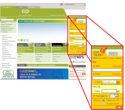
Figure 4 shows the testing process developed, which will be explained in detail in the following chapters. As an illustrative example the search service of the Alpha and Intercity trains (Figure 5) from CP - Comboios de Portugal2 - will be used. More complex examples will be
presented in Section 5. This example is only used due to its simplicity, which facilitates the understanding of the testing process developed.
Figure 4 - Process of generating and executing test cases
2 Available at: http://cp.pt/
4.2 Task Models with CTT (ConcurrTaskTree)
A simple approach to represent user interaction with a system is as said before, the use of task models. A task model allows the representation of activities to be performed to achieve a certain goal. The support tool of choice for the design of task models is TERESA. This tool supports the CTT notation (ConcurTaskTrees) [20] and provides, in addition to the creation of a task model, the generation of a finite state machine (in form of Presentation Task Sets - PTS) that represents the behavior of the model.
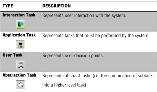
CTT is a language that supports Hierarchical Task Analysis. Thus, a CTT model is a tree in which the hierarchical decomposition of tasks into subtasks that must be performed to achieve a specific goal (the tree root) is carried out. Different interactions may be represented by one of the four possibilities provided by the language, as illustrated in Table 2.
TYPE DESCRIPTION
Interaction Task Represents user interaction with the system.
Application Task Represents tasks that must be performed by the system.
User Task Represents user decision points.
Abstraction Task Represents abstract tasks (i.e. the combination of subtasks into a higher level task)
Table 2 - Type of tasks
All types mentioned above, except abstract tasks, should appear as leaves of the tasks models that are to be built. An abstract task should be used to structure the model and must appear only as an internal node of the tree.
In addition to different types of tasks the language also provides operators to model tree traversal (i.e. how to combine different sub-tasks at the same level in the tree). The available operators and their purpose can be found in Table 3.
OPERATOR DESCRIPTION
[Task] Optional task operador: The task is optional so it might not be
executed
Task * Iterative operator: The task is repeated.
Task1 [ ] Task2 Choice operator: Choose which of two tasks will be performed. Task1 |=| Task2
Order Independence operator: The two tasks have to be
performed, but when one starts the other has to wait for the first to finish its execution.
Task1 ||| Task2 Independent current operator: Two tasks can be executed
concurrently
Task1 |[ ]| Task2
Concurrent with Information Exchange operator: Two tasks can
be performed concurrently, but need to be synchronized as they will exchange information with each other.
Task1 [> Task2 Deactivation operator: When the task on the right is activated the
one on the left is deactivated.
Task1 |> Task2
Suspende/Resume operator: The task of the right can stop the task
on the left. Once the task on the right finishes its execution, the task of the left continues its execution from the point where it was interrupted.
Task1 >> Task2 Enabling operator: The task on the right is executed when the task
on its left finishes its execution.
Task1 [ ]>> Task2
Enabling with Information Passing operator: The task of the right
begins to run once the task on its left finish its execution. The task on the left transmits information to the task on the right.
As it can be seen in the table, most operators are applied to pairs of tasks. There is no limit to the number of children a node can have. The only requirement is that all nodes must be related to their adjoining nodes by one of the operators. Operators in the table are presented in decreasing order of priority.
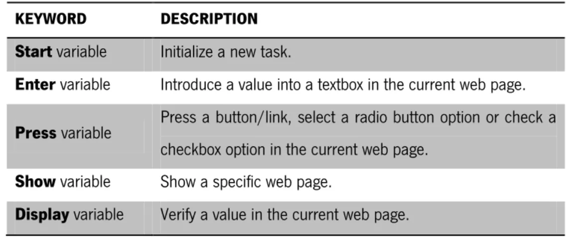
In order to facilitate the automatic generation of test cases, a set of rules to name the sub-tasks in the model were defined (adapted from [7]). All tasks are obliged to have a name (the tool allows tasks not to have a name). The name of the tasks must then be composed of a keyword and a variable. Keywords are used to define the type of action the user or system will perform. Table 4 lists the defined keywords and their respective function.
KEYWORD DESCRIPTION
Start variable Initialize a new task.
Enter variable Introduce a value into a textbox in the current web page.
Press variable Press a button/link, select a radio button option or check a
checkbox option in the current web page.
Show variable Show a specific web page.
Display variable Verify a value in the current web page.
Table 4 – Keyords defined
The task model in Figure 6 represents the search for Alfa and intercity trains in CP’s webpage. In this example only the search from origin to destination was modeled and not both origin-destination and destination-origin. To simplify the testing process (to only have a path navigating the tree) only the enabling operator (>>) was used. Other operators are used in the cases studies presented in Section 5.
Figure 6 – Alfa and intercity trains search in CP
For a valid train search is necessary to fill the origin (Enter origin) and destination (Enter destination) fields with valid train station names, and also select a valid date (Enter date). Once these are filled it is then necessary to press the OK button (Press confirmation). With correct values in the fields a new page will be shown with the trains options (Show results). In case of error a notification is displayed in the browser but the element is not represented in HTML (an alert window is used) and cannot be mapped to the model, hence we have decided not to model it here.
4.3 Test Cases
4.3.1 Test Cases Configuration
As stated above, from the task model it is possible, using TERESA, to generate a finite state machine called a PTS representing the behavior of the model. Together with the PTS is also necessary to define two configuration files. A file mapping variables in the model to elements in the interface (see Figure 7) contains, for each variable in the model what kind of HTML element to find on the web page, how to find it (which attribute), etc.. This file must contain the definition of all the variables in the task model. An additional variable must also be included in this file –
urlStart. This variable is important to define the Web Page where we want to find the HTML
elements.
For each variable in the model there is a line in the file (see syntax in Figure 7):
Variable: name of the task in the task model.
Keyword: one of the keywords: Press, Enter, Show, Display.
ElementType: Class WatiN that mapps the HTML element (to be explain later).
FindBy: the attribute through which we want to find the HTML element on the web page.
ValueToFind: the value of the attribute.
Parameter: the parameter is only available and required for Label, Textbox and Textarea elements, and is used to indicate which values to use for input (Textbox and Textarea)/ expected in the output (Label). Instead of concrete values, in this file the name of a parameter is indicated. The value of the parameter must be defined in the test cases configuration file.
The input values to be used during testing are stored in another configuration file (see Figure 8). Thus, the software tester can define different test cases from the same behavior (by changing the input values).
urlStart?URL
Variable?KeyWord=ElementType=FindBy!ValueToFind[=parameter] ...
Figure 7 - Mapping file structure
NumberOfTestCases parameter?value ...
The file contains a sequence of test cases. Each test case is a sequence of assignments of values to the parameter used in the mapping file. The content of the file is as follow:
NumberOfTestCases: the number of tests that are defined.
Parameter: the parameter used in the mapping file.
Value: the value that we want to see in the HTML element.
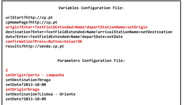
For the example of Figure 6, the configuration files being created would have the contents shown in Figure 9. In the example, the variable confirmation is a button and the HTML element is found in the Web page through the attribute Value with the value "OK" (<input type="submit" value="OK"/>). In the same example it is also possible to observe that the variable origin is a textbox, which should be found on the Web page by the attribute Name and the value “departStationName”. As indicated the value to be filled in the text box is set in the setOrigin parameter.
Observing the parameters configuration file, we can see that two test cases are defined. Each assigns different values to the setOrigin, setDestination and setDate parameters.
Variables Configuration File: urlStart?http://cp.pt cpHomePage?http://cp.pt origin?Enter=TextFieldExtended=Name!departStationName=setOrigin destination?Enter=TextFieldExtended=Name!arrivalStationName=setDestination date?Enter=TextFieldExtended=Name!departDate=setDate confirmation?Press=Button=Value!OK results?http://venda.cp.pt
Parameters Configuration File: 2 setOrigin?porto - campanha setDestination?braga setDate?2013-10-08 setOrigin?braga setDestination?Lisboa - Oriente setDate?2013-10-09
The identification of the type of HTML element to be used in the configuration file of the variables is important. The developed tool generates code to automatically test the user interface. WatiN is used because it provides the functionality to interact programmatically with the interface, allowing the simulation of user events in order to execute the test cases without requiring human intervention. The correspondences between the HTML elements and proper class in WatiN can be found in Tables 5 and 6 3
It is important to note that the inclusion of the keyword in the configuration file is due to the fact that it is extremely important to determine how the code will be generated. Depending on the keyword, generated code will vary. For example, for the Enter keyword code will be generated for the setting the value of the corresponding HTML element. If the keyword is Press the code will be generated for clicking the HTML element.
HTML ELEMENT WATIN CLASS
<a/> Link <area/> Area <button/> <input type=button/> <input type=reset/> <input type=submit/> Button <div/> Div <form/> Form <frame/> <iframe/> Frame <frameset/> FrameCollection
Table 5 - Correspondences between the HTML elements and WatiN Classes
HTML ELEMENT WATIN CLASS
<img/>
<input type=image/> Image <input type=checkbox/> CheckBox
<input type=file/> FileUpload
<input type=hidden/> <input type=password/> <input type=text/> <textarea/>
TextField
<input type=radio/> RadioButton
<label/> Label <option/> Option <p/> Para <select/> Select <span/> Span <table/> Table <tbody/> TableBody <td/> TableCell <tr/> TableRow
Table 6 - Correspondences between the HTML elements and WatiN Classes (continuation)
4.3.2 Test Cases Generation
The developed tool used an internal structure in the form of a graph, which stores all the information contained in the files. With this graph the tool is able to find paths between various nodes (derived from the PTS states) and with that information create test cases. Each node represents a method with one or more actions to be performed on the website (for which the model was designed). Each path found (Figure 10) defines the correct order of calling each
method generated (List 1). Note that one method will be generated for each task in the task model with the keywords Show, Enter, Press and Display (the latter was not used in this example).
Figure 10 - Path found for the CP example
public void cpHomePage(string url) {
try {
if (!browserInstance.Url.Contains(url)) {
using (System.IO.StreamWriter file = new
System.IO.StreamWriter(@"C:\WatiN\CaseStudy\TestProject\log.txt", true)) {
file.WriteLine("Method cpHomePage: The page was not found: " + url); } Environment.Exit(0); } } catch(Exception e) {
using (System.IO.StreamWriter file = new
System.IO.StreamWriter(@"C:\WatiN\CaseStudy\TestProject\log.txt", true)) {
file.WriteLine("An error was found while exectuing cpHomePage(): " + e.Message);
}
Environment.Exit(0);
} }
public void origin(string setOrigin) {
try {
TextField departStationName = browserInstance.TextField(Find.ByName ("departStationName")); departStationName.Value = setOrigin; } //... } 1 [Show cpHomePage] 2 [Enter origin] 3 [Enter destination] 4 [Enter date] 5 [Press confirmation] 6 [Show results]
//...
public void confirmation() {
try {
Button OK = browserInstance.Button(Find.ByValue("OK")); OK.Click();
} //... }
public void results(string url) {
try {
if (!browserInstance.Url.Contains(url)) {
using (System.IO.StreamWriter file = new
System.IO.StreamWriter(@"C:\WatiN\CaseStudy\TestProject\log.txt", true)) {
file.WriteLine("Method results: The page was not found: " + url); } Environment.Exit(0); } } //... } [TestMethod]
public void testMethod1() {
cpHomePage("http://cp.pt"); origin("porto - campanha"); destination("braga"); date("2013-10-08"); confirmation(); results("http://venda.cp.pt"); } [TestMethod]
public void testMethod2() {
cpHomePage("http://cp.pt"); origin ("braga");
destination ("Lisboa - Oriente"); date("2013-10-09");
confirmation ();
results("http://venda.cp.pt"); }
4.4 Test Cases Mutation
In order to test the system under user error conditions, the possibility of changing (mutating) the test cases to represent user error was studied. There are three main types of user errors [21]:
Slips – a change in the order of execution of two actions.
Lapses – the omission of an action.
Mistakes - performing an action with a wrong value.
Following these types of errors, three different methods were developed to perform mutations in the test cases. The introduction of errors is performed with the information found in the paths in the graph. Slip type errors are generated swapping the order of execution of two methods of the path found. The choice of which position to be swapped is made randomly.
The generation of Lapse errors appeals also to the random choice of a method. However unlike Slip errors, in this type of error the method chosen is eliminated from the path.
Finally, Mistake errors are generated only in methods that take input parameters. In this case, a character is inserted in one of the input parameters of the method (both randomly chosen). Examples of generating mutated test cases can be seen in List 2 (compare with the first test cases in List 1).
//Slip Mutation [TestMethod]
public void mutatedTestMethod1() {
cpHomePage("http://cp.pt"); confirmation();
destination("braga"); date("2013-10-08");
origin("porto - campanha"); results("http://venda.cp.pt"); }
//Lapse Mutation [TestMethod]
public void mutatedTestMethod2() {
cpHomePage("http://cp.pt"); origin ("porto - campanha"); date("2013-10-08"); confirmation(); results("http://venda.cp.pt"); } //Mistake Mutation [TestMethod]
public void mutatedTestMethod3() {
cpHomePage("http://cp.pt"); origin("por#o - campanha"); destination ("braga"); date("2013-10-08"); confirmation();
results("http://venda.cp.pt"); }
List 2 - Mutated test cases generated for each type of mutation identified
In the first mutated test case the order between filling the origin station and pressing the button (confirmation method) has been changed. The second case tests forgetting to fill the destination station (which was deleted from the test case). Finally, the third case simulates an error filling the origin station.
4.5 Test Cases Execution
WatiN (Web Application Testing in. NET) is a framework that, as previously mentioned, can open instances of a Web browser (Internet Explorer 6 or higher and Firefox 2 and 3) and then find page elements by multiple attributes. Using this framework it is then possible to run the test cases (Figure 11). In case of success an entry is written to a log file to mention that the method was performed without any problem. In cases where an abnormality is detected, test execution is completed and an entry is written to the log file where it is possible to visualize what happened wrong during test execution. Among the anomalies may be, for example, a failure when trying to find the HTML elements on the Web page under test.
It must be noted that these abnormalities do not necessarily mean an error from the implementation. This will have to be determined by analysis of the case. For example, due to the introduction of errors in the test cases, it is possible that if the test fails because the interface does not allow execution of the case as defined (for example, when there is no password or the user name is wrong if we are conducting a test to a login system). Unless the task model provides these possibilities, the aim is for the test to fail. For the case described, when the values defined in the test were correct the tests cases were successfully performed.
[TestMethod]
public void testMethod1() {
cpHomePage("http://cp.pt"); origin("porto - campanha"); destination("braga"); date("2013-10-08"); confirmation();
results("http://venda.cp.pt"); }
A software tester needs to analyze the results of the tests. For that he can visualize the results presented in Visual Studio (Figure 12) and the generated log file (Figure 13). Using Visual Studio (VS) brings the possibility of making use of testing options integrated in it. For this project the WatiN framework was used in a VS Test Project. The log file generated for each entry states the method that was executed and the result of its execution.
For a graphical representation of the test cases the software tester also has access to a graph generated by the tool (Figure 14). This graph is merely informative of the sequence that the test case has followed.
Figure 14 - Generated grpah for the test case
Method cpHomePage: The page was found: http://cp.pt
Method origin: The correct value was found in departStationName Method destination: The correct value was found in arrivalStationName Method date: The correct value was found in departDate
Method confirmation: The action OK was successfully executed. Method results: The page was found: http://venda.cp.pt
4.6 Conclusion
This chapter has presented the proposed approach to the Model-based Testing of web applications’ user interfaces. The modeling language used to describe the oracle, and the configuration files to create the test cases were described, as was the approach used to consider user error in the testing phase. A small example has been used to illustrate the approach. More examples are provided in the next chapter.
5. TESTING USER INTERFACES
This chapter presents two case studies designed to demonstrate the application of the developed tool. The first case study depicts the search of flights and hotels on the TAP website. The second case is about the use of some features of the online version of Microsoft Outlook.
For each case study a task model, configuration files and samples of generated code are presented.
5.1 TAP Portugal – Search flights and hotels
The TAP Portugal example tests the flights and hotels search functionality provided at TAP’s web site4 (see Figure 15).
5.1.1 Task Model
The excerpt from the task model in Figure 16 represents the tasks necessary to conduct to search for flights (only one way) on TAP web page (Figure 15). To perform this type of search it is necessary to select the "Só ida" option and fill, at least, the fields “De”, “Para“ and “Partida”. The complete task model can be found in Appendix I.
Figure 16 - TAP Task Model sample
5.1.2 Configuration Files
The configuration files are a key point for code generation because it is in them that the mapping between the interface and the task model is specified. Figure 17 illustrates this mapping, showing how each task in the model (on the right) corresponds to some element in the user interface. Boxes with the same color denote related elements. The respective configuration files can be viewed in Figure 18. Only one set of input parameters is being specified. In this case, corresponding to a search for flights from Porto to Barcelona on November 6, 2013.
5.1.3 Test Cases
Once the configuration files step is completed, the process of generating code can start. The tool will start by creating a graph structure to be able to find execution paths. The paths found will be our test cases with the correct order of execution of the methods generated. The paths for the TAP example can be seen in Figure 19 (the second path matches the example presented in Figures 15 and 16).
Variables Configuration File: urlStart?http://www.flytap.com/Portugal/pt/Homepage homePage?http://www.flytap.com/Portugal/pt/Homepage ida?Press=RadioButton=Id!IDA origem_ida?Enter=TextField=Name!fromCity=cidadeOrigem destino_ida?Enter=TextField=Name!toCity=cidadeDestino data_ida?Enter=TextField=Name!data_partida=dataIda reservar?Press=Span=Text!Reserve Ja results? http://book.flytap.com
Parameters Configuration File: 1
cidadeOrigem?Porto, Portugal cidadeDestino?Barcelona, Espanha dataIda?06/11/2013
Figure 19 - Paths found for TAP task model
Once the paths are found the test cases can be generated as presented in List 3. The full listing of the generated code can be found in Appendix III.
1 [Show homePage] 2 [Press hotel] 12 [Enter destino_hotel] 13 [Enter checkin] 14 [Enter checkout] 15 [Press reservar_ hotel] 16 [Show resultados_ hotel] 1 [Show homePage] 2 [Press ida] 9 [Enter origem_ida] 10 [Enter destino_ida] 11 [Enter data_ida] 7 [Press reservar] 8 [Show resultsl] 1 [Show homePage] 2 [Press idaEvolta] 3 [Enter origem_ida Evolta] 4 [Enter destino_ida Evolta] 5 [Enter dataPartida] 6 [Enter dataRegr esso] 7 [Press reservar] 8 [Show results]
[TestMethod]
public void testMethod1_1() { homepage("http://www.flytap.com/Portugal/pt/Homepage"); hotel(); destino_hotel("Barcelona"); checkin("06/11/2013"); checkout("13/11/2013"); reservar_hotel(); resultados_hotel("http://book.flytap.com"); } [TestMethod]
public void testMethod2_1() {
homepage("http://www.flytap.com/Portugal/pt/Homepage"); ida();
origem_ida("Porto, Portugal"); destino_ida("Barcelona, Espanha"); data_ida("06/11/2013");
reservar();
results("http://book.flytap.com"); }
[TestMethod]
public void testMethod3_1() {
homepage("http://www.flytap.com/Portugal/pt/Homepage"); idaEvolta();
origem_idaEvolta("Porto, Portugal"); destino_idaEvolta("Barcelona, Espanha"); dataPartida("06/11/2013");
dataRegresso("13/11/2013"); reservar();
results("http://book.flytap.com"); }
List 3 - Generated test cases for TAP task model
5.1.4 Test Cases Execution
Figure 20 shows the execution of the test case that performs the search of flights for Barcelona from Porto on the specified date.
Figure 20 - TAP test case execution example
[TestMethod]
public void testMethod2_1() {
homepage("http://www.flytap.com/Portugal/pt/Homepage"); ida();
origem_ida("Porto, Portugal"); destino_ida("Barcelona, Espanha"); data_ida("06/11/2013");
reservar();
results("http://book.flytap.com"); }
The results of the test cases executed can be viewed (an entry for each test case) in Visual Studio (Figure 21). If everything goes as plan the Visual Studio shows the test as Passed. The log file (Figure 22) can also give information to the software tester.
Figure 21 - Test results presented in Visual Studio 2010
5.1.5 Mutated Test Cases
If during the code generation the tester chose an option to mutate the test cases, for each test case a mutated test case will be created. Note that for each run only one type of mutation can be chosen. List 4 shows examples of mutated test cases, for each type (Slip, Lapse and Mistake), generated by the tool for the TAP task model.
Method homePage: The page was found: http://www.flytap.com/Portugal/pt/Homepage
Method ida: The action IDA was successfully executed. Method origem_ida: The correct value was found in fromCity Method destino_ida: The correct value was found in toCity Method data_ida: The correct value was found in data_partida Method reservar: The action Reserve_Ja was successfully executed. Method results: The page was found http://book.flytap.com
![Figure 1 - STLC stages and performed order (adapted from [9])](https://thumb-eu.123doks.com/thumbv2/123dok_br/17798959.840674/19.892.127.777.437.503/figure-stlc-stages-performed-order-adapted.webp)
![Table 1 - Software Testing Life Cycle phases (adapted from [10])](https://thumb-eu.123doks.com/thumbv2/123dok_br/17798959.840674/20.892.113.774.177.762/table-software-testing-life-cycle-phases-adapted.webp)
![Figure 2 - V-Model (adapted from [12])](https://thumb-eu.123doks.com/thumbv2/123dok_br/17798959.840674/23.892.244.649.636.981/figure-v-model-adapted-from.webp)
![Figure 3 - Model-based testing process (Adapted from [12])](https://thumb-eu.123doks.com/thumbv2/123dok_br/17798959.840674/27.892.269.599.217.699/figure-model-based-testing-process-adapted.webp)