A SMART MICROGRID LABORATORY PLATFORM CONCEPTUAL
DESIGN FOR UNIVERSITY CAMPUS
PROJETO CONCEITUAL DE PLATAFORMA LABORATORIAL DE
MICRO REDE INTELIGENTE PARA CAMPUS UNIVERSITÁRIO
JOSMELA SHANTAL KOENDJBIHARIE - CRISIS
DISSERTAÇÃO DE MESTRADO EM SISTEMAS MECATRÔNICOS DEPARTAMENTO DE ENGENHARIA MECÂNICA
UNIVERSIDADE DE BRASÍLIA FACULDADE DE TECNOLOGIA
DEPARTAMENTO DE ENGENHARIA MECÂNICA
PROGRAMA DE PÓS-GRADUAÇÃO EM SISTEMAS MECATRÔNICOS
PROJETO CONCEITUAL DE PLATAFORMA LABORATORIAL DE MICRO REDE INTELIGENTE PARA CAMPUS UNIVERSITÁRIO
A SMART MICROGRID LABORATORY PLATFORM CONCEPTUAL DESIGN FOR UNIVERSITY CAMPUS
JOSMELA SHANTAL KOENDJBIHARIE - CRISIS
ORIENTADOR: RUDI HENRI VAN ELS Dr. Eng.
DISSERTAÇÃO DE MESTRADO EM SISTEMAS MECATRÔNICOS
PUBLICAÇÃO: ENM.DM – 108/16
UNIVERSIDADE DE BRASÍLIA FACULDADE DE TECNOLOGIA
DEPARTAMENTO DE ENGENHARIA MECÂNICA
PROGRAMA DE PÓS-GRADUAÇÃO EM SISTEMAS MECATRÔNICOS
PROJETO CONCEITUAL DE PLATAFORMA LABORATORIAL DE MICRO REDE
INTELIGENTE PARA CAMPUS UNIVERSITÁRIO
JOSMELA SHANTAL KOENDJBIHARIE - CRISIS
DISSERTAÇÃO DE MESTRADO SUBMETIDA AO DEPARTAMENTO DE ENGENHARIA MECÂNICA DA FACULDADE DE TECNOLOGIA DA UNIVERSIDADE DE BRASÍLIA COMO PARTE DOS REQUISITOS
NECESSARIOS PARA OBTENÇÃO DO GRAU DE MESTRE EM SISTEMAS MECATRÔNICOS.
APROVADA POR:
RUDI HENRI VAN ELS, Dr. Eng. (UnB/FGA) (ORIENTADOR)
ANDREA CRISTINA DOS SANTOS, Dr(a). Eng. (UnB/EPR) (EXAMINADOR INTERNO)
LOANA NUNES VELASCO, Dr(a). Eng. UnB/FGA) (EXAMINADOR EXTERNO)
FICHA CATALOGRÁFICA
REFERÊNCIA BIBLIOGRÁFICA
KOENDJBIHARIE - CRISIS, J. S. (2016). Projeto conceitual de plataforma laboratorial de micro rede inteligente para campus universitário. Publicação ENM.DM-108/16,
Departamento de Engenharia Mecânica, Universidade de Brasília, Brasília, DF, 144 p.
CESSÃO DE DIREITOS
NOME DO AUTOR: Josmela Shantal Koendjbiharie - Crisis
TÍTULO DA DISSERTAÇÃO DE MESTRADO: Projeto conceitual de plataforma laboratorial de micro rede inteligente para campus universitário.
GRAU / Mestre ANO / 2016.
É concedida a Universidade de Brasília a permissão para reproduzir cópias desta dissertação de mestrado e para emprestar ou vender tais cópias somente para propósitos
acadêmicos e científicos. O autor reserva outros direitos de publicação e nenhuma copia para esta dissertação de mestrado pode ser reproduzida sem a autorização por escrito do autor.
_____________________________________ Josmela Shantal Koendjbiharie - Crisis SCRN 712/713 Bloco E apto 103, Asa Norte CEP: 70760-650 – Brasília/DF – BRASIL e-mail: j_crisis@yahoo.com
KOENDJBIHARIE - CRISIS, JOSMELA SHANTAL
Projeto conceitual de plataforma laboratorial de micro rede inteligente para campus universitário.
[Distrito Federal] 2016
iv, 144p., 210 x 297 mm (ENM/FT/UnB, Mestre, Sistemas Mecatrônicos, 2016) Dissertação de Mestrado – Universidade de Brasília.
Faculdade de Tecnologia. Departamento de Engenharia Mecânica.
1. Micro rede inteligente 2. Modular design
3. Integração de energias renováveis; 4. Projeto conceitual
AGRADECIMENTOS
Quero agradecer ao meu Pai o SENHOR Deus, pela vida, força, motivação, luz, conselho e muita coragem por meus dias difíceis durante neste caminho de mestrado.
Ao meu marido Marlon Koendjbiharie pelo amor, paciência e apoio e a minha amada filha Lyoni Koendjbiharie para ser a alegria e motivador na minha vida.
Aos meus pais Leonard Orlando Crisis e Lucia Yvonne Gödeken-Crisis pelo amor, confiança e educação, e aos meus irmaõs Priscilla, Sharon e Harvey pela motivação.
Ao meu orientador, professor Rudi Henri van Els, pelo ensino, paciência, disposição e apoio.
Aos professores Andrea Dos Santos, Loana Nunes Velasco, Rafael Shayani e Anésio de Leles Ferreira Filho pela contribuição no desenvolvimento deste trabalho.
Aos meus colegas de laboratório Giselle Leite, Thiago e Pedro Lucas de Souza pelo apoio e tempo.
RESUMO
Esta pesquisa tem como objetivo a apresentação de uma estrutura para um microrede inteligente num campus universitário. A metodologia usada é baseada no processo de projeto modular. O trabalho se inicia com uma revisão da literária sobre o estado da arte de microgrids e smartgrids, um sistema de monitoramento de dados de energia como uma instalação de cama de teste, e em seguida um método de projeto de sistemas modulares para desenvolver um conceito da plataforma smart microgrid (SMGP). Esta pesquisa apresenta as duas fases do projeto modular: o projeto informacional e o projeto conceitual. Os resultados do projeto informacional são as especificações técnicas do SMGP proposto, e o projeto conceitual apresenta as funções básicas contribuindo aos conceitos da SMGP, por meio da decomposição de uma estrutura funcional global da SMGP. Para identificar os módulos na fase de projeto conceitual um método heurístico é usado. A implementação deste método resultou na identificação de quatro módulos da SMGP: o módulo de geração de energia renovável e armazenamento, o módulo de geração de backup de energia, o módulo de alimentação da distribuidora e o módulo de gerenciamento, monitoramento e controle de energia. Um laboratório de smart microgrid para o curso de Engenharia de Energia do campus Gama da Universidade de Brasília para fins educacionais é uma necessidade clara. A proposta de usar a rede elétrica deste campus e integrar nela fontes de energia renováveis como parte do laboratório é feita nesta pesquisa. Esta plataforma de smart microgrid é uma estrutura básica a ser implementada em qualquer campus universitário para atender a sua necessidade de um ambiente de laboratório smart microgrid. A abordagem SMGP justifica uma proposta esquemática e estruturada do sistema previsto, e suporta o projeto do SMGP em módulos. Inicialmente o SMGP é apresentado como um sistema geral em qualquer campus universitário, e finalmente o projeto do SMGP a ser implementado no campus Gama é apresentado. No presente trabalho três conceitos de SMGP são gerados como alternativas, usando o conceito selecionado como base de projeto modular do ambiente de laboratório do campus Gama.
ABSTRACT
This research work aims to present a basic framework for a smart microgrid on a university campus. The methodology used in this research is mainly based on the modular design process. This work is initiated with a literature review of the state of the art of microgrids and smartgrid, an implemented energy data monitoring system as a testbed installation, and followed with a modular system design method to develop a concept of the smart microgrid platform (SMGP). This research presents the two phases of the adapted modular system development method: the informational and the conceptual design. The informational design results in the technical specifications of the proposed SMGP and the conceptual design method presents through decomposing of a global functional structure of the SMGP, the elementary functions which will attribute to the generation of concepts of the SMGP. To identify the modules in the conceptual design phase the heuristic method is used. This heuristic method was invented by Stone (1997) and depends on the functional structure of the system or product to be developed. The implementation of this method resulted in the identification of four modules of the SMGP: the renewable energy generation and storing module, the backup-energy generation module, utility power supply module and, the energy management, monitoring and control module. A smart microgrid laboratory for the Energy Engineering course of the campus Gama University of Brasília is a clear necessity for educational purposes. A proposal was made to use the complete electrical grid of the campus and to integrate renewable energy sources as part of this micro grid laboratory. This smart microgrid platform design concept is a basic structure to be implemented by any university campus to suit their needs for a smart microgrid laboratory environment. This SMGP modular approach justifies in a schematic and structural proposal of the needed system, and supports the SMGP design in modules. This SMGP system is firstly presented as a general system to be implemented at any campus university and finally is presented the SMGP on the campus Gama to be implemented. In this work three concepts for the SMGP are generated and the selected concept alternative is used as modular design to be applied as a laboratory environment on the campus Gama.
RESUMO ...vii
ABSTRACT ... viii
LIST OF FIGURES... xi
LIST OF TABLES ... xiii
LIST OF SYMBOLS AND ABREVATIONS ... xiv
CHAPTER 1. INTRODUCTION ... 1
1.1 TRANSFORMATION OF ENERGY GENERATION ...1
1.2 MOTIVATION...3
1.3 OBJECTIVES ...6
1.4 STRUCTURE OF DISSERTATION ...6
CHAPTER 2. STATE OF THE ART OF MICRO GRIDS AND THE MODULAR DESIGN APPROACH ... 7
2.1 MICROGRID ...7
2.1.1 MICROGRID CLASSIFICATIONS AND TYPES ... 10
2.2 MICROGRID TECHNOLOGY ... 13
2.2.1 MICROGRID ENERGY GENERATION TECHNOLOGIES ... 15
2.2.2 MICROGRID ENERGY STORAGE TECHNOLOGIES ... 15
2.2.3 MICROGRID INTERFACE TECHNOLOGY ... 16
2.2.4 MICROGRID SWITCH TECHNOLOGIES FOR INTERCONNECTION... 20
2.4 THE SMART MICROGRID ... 22
2.5 EXAMPLES OF (SMART) MICROGRIDS ... 27
2.5.1 SMART MICROGRIDS IN BRAZIL ... 30
2.6 MODULAR DESIGN APPROACH FOR THE SMGP ... 32
2.6.1 THE MODULAR DESIGN METHOD ... 32
2.6.2 PROPOSED MODULAR DESIGN METHOD FOR THE SMGP SYSTEM ... 37
2.7 FINAL CONSIDERATIONS... 39
CHAPTER 3. INFORMATIONAL DESIGN OF MODULAR SYSTEM ... 41
3.1 THE PROBLEM DEFINITION ... 41
3.1.1 THE CAMPUS GAMA ... 42
3.1.2 THE TARIFF STRUCTURE AND ANALYSIS OF CAMPUS GAMA ... 45
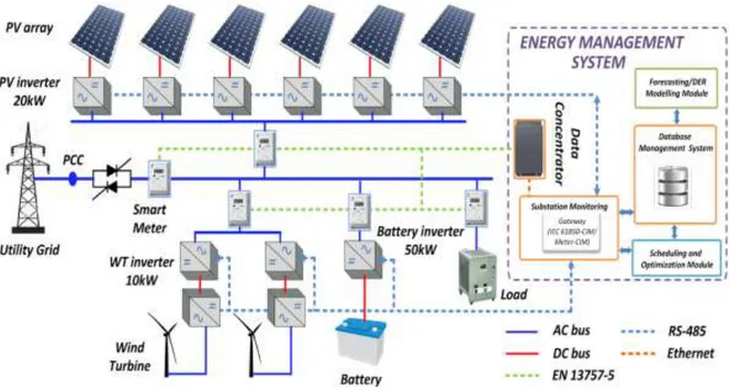
3.1.3 IMPLEMENTED ENERGY MONITORING INFRASTRUCTURE ... 50
3.2 INFORMATIONAL DESIGN OF MODULAR SYSTEM... 56
3.3 FINAL CONSIDERATIONS ... 81
CHAPTER 4. CONCEPTUAL DESIGN OF MODULAR SYSTEM ... 83
4.2 STAGE 2.1 ARRANGEMENT OF THE FUNCTIONAL SYNTHESIS OF THE
SYSTEM ...85
4.2.1 TASK 2.1.1 IDENTIFICATION OF THE GLOBAL FUNCTION OF THE SYSTEM 85 4.2.2 TASK 2.1.2 ESTABLISHMENT OF THE PARTIAL FUNCTIONS ... 86
4.2.3 TASK 2.1.3 ESTABLISHMENT OF STRUCTURED ELEMENTARY FUNCTIONS ... 87
4.3 STAGE 2.2 SEARCH FOR SOLUTION PRINCIPLES ... 91
4.3.1 TASK 2.2.1 CHOOSE THE BEST FUNCTIONAL STRUCTURE TO MEET SYSTEM DESIGN PROBLEM ... 91
4.3.2 TASK 2.2.2 DEVELOP SOLUTION PRINCIPLES FOR THE IDENTIFIED ELEMENTARY FUNCTIONS ... 92
4.4 STAGE 2.3 GENERATE CONCEPTS OF THE SMG SYSTEM ... 98
4.4.1 TASK 2.3.1 IDENTIFY THE MODULES FOR THE DESIGN CONCEPTS ... 98
4.4.2 TASK 2.3.2 ESTABLISH MODULAR SMG DESIGN CONCEPT ... 104
4.4.3 SELECTING AN ALTERNATIVE CONCEPT ... 111
4.5 FINAL CONSIDERATIONS ... 115
CHAPTER 5. CONCLUSION AND FUTURE WORKS ... 116
5.1 CONCLUSIONS ... 116
5.2 FUTURE WORKS ... 118
BIBLIOGRAPHIC REFERENCES ... 119
ANNEX ... 125
ANNEX QUALITY FUNCTION DEPLOYMENT (QFD) ... 125
ANNEX CAMPUS GAMA ENERGY CONSUME, DEMAND AND TARIFF STRUCTURE DATA ... 127
LIST OF FIGURES
Figure 1: A physical view of the Microgrid with its individual elements ... 10
Figure 2: Industrial Microgrid Source: Adapted from SIEMENS (2011) ... 11
Figure 3: Campus/Institutional Microgrid ... 12
Figure 4: Island Microgrid ... 12
Figure 5: Utility microgrid ... 13
Figure 6: Architecture of a microgrid based on the technologies ... 14
Figure 7. Topology of smart micro grid ... 23
Figure 8: The main characteristics of a smart grid... 25
Figure 9. The product/system development process by Ulrich and Eppinger (2012) ... 35
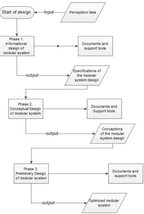
Figure 10. Flowchart of the followed roadmap for the modular system design of SMGP... 39
Figure 11: Campus Gama as projected on the left and on the right is the current state presented ... 43
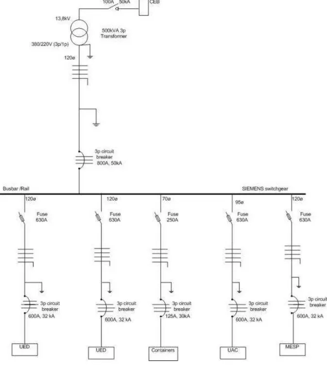
Figure 12. Electric schematic diagram of campus ... 44
Figure 13. Electrical diagram of campus expansion with containers ... 45
Figure 14.Consume of campus Gama in year 2014 ... 49
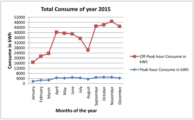
Figure 15. Consume of campus Gama in year 2015 ... 49
Figure 16: The SENTRON PAC 3100 multi-meter ... 51
Figure 17: RS485/RS232 Converter ... 53
Figure 18: Diagram of monitoring system of campus Gama ... 54
Figure 19: Typical power profile of part of UED building ... 55
Figure 20. Product Life-cycle for the microgrid laboratory platform ... 58
Figure 21. Stakeholder structural organization ... 66
Figure 22. Graphical representation of the global function ... 85
Figure 23. The global function of the SMG system ... 86
Figure 24. Partial Functions of the SMG system ... 87
Figure 25. Elementary functions of SMGP system 1 ... 88
Figure 26. Elementary functions of SMGP system 2 ... 89
Figure 27. Elementary functions of SMGP system 3 ... 90
Figure 28. Dominant flow heuristic applied to a generic function structure. ... 99
Figure 29. Flow branching heuristic applied to a generic function structure ... 100
Figure 30. Conversion–transmission applied to a generic set of sub-functions ... 100
Figure 31. Dominant flow heuristic identified modules of the SMG system ... 101
Figure 32. The branching flow heuristc for module identification in the SMG system ... 102
Figure 33. The Conversion-Transmission flow heuristic for the SMGP ... 103
Figure 36. Concept 3 of the SMGP system ... 108
Figure 37. The SMGP installation location on the campus Gama ... 114
Figure 38. The horizontal and vertical wind turbine configurations ... 133
Figure 39. Photovoltaic build up from cell to array ... 134
Figure 40. Photovoltaic types ... 136
Figure 41. (a) Smart microgrid (SMG) customer premises domain and hierarchical zones; (b) Microgrid three layers communication network construction ... 138
LIST OF TABLES
Table 1 Distributed Generation Technologies of microgrids ... 16
Table 2. A summary of existing energy storage technologies ... 18
Table 3. A summary of power electronics conversion technologies ... 19
Table 4 Summary of interface technologies of the microgrid ... 20
Table 5: A summary of the microgrid switch technologies... 21
Table 6: Analysis of the various control techniques in AC and DC microgrids ... 22
Table 7. Smart grid technologies ... 26
Table 8: Several smart microgrids around the world ... 28
Table 9. Definitions for ´´modularization´´ from the engineering literature ... 33
Table 10. Modular Design Methodologies ... 35
Table 11. Review of Modular Design method from different ... 36
Table 12. Consume, Demand and Tariffs of campus Gama ... 48
Table 13. The roadmap followed for the informational design stage of the modular system. ... 57
Table 14. Challenges to developing and operating testbeds related to smartgrid technologies ... 63
Table 15. Stakeholder analysis ... 67
Table 16. The requirementsof the client in the system life cycle ... 70
Table 17. Mudge diagram with the requirements of the client ... 71
Table 18. The requirements of the client in hierarchical structure ... 72
Table 19. Transformation of the requirements of the client into requirements of the modular system (design) ... 74
Table 20. Results of the Quality Function Deployment ... 76
Table 21. Design specifications of the system... 78
Table 22. Roadmap for SMGP conceptual design phase ... 84
Table 23. Matrix of selection of the alternative functional structure ... 92
Table 24. Matrix for selection of alternative solution principles for the functional structure ... 94
Table 25. Pugh Matrix for selecting a concept ... 112
LIST OF SYMBOLS AND ABREVATIONS
A Ampére
V W/m^2
Voltage Irradiance
UnB Universidade de Brasília
SMG Smart MicroGrid
SMGP Smart MicroGrid Platform
W Watt
KWh kiloWatt hour
PV Photovoltaic
SCADA Supervisory Control And Data Acquisition
AC Alternating Current
DC Direct Current
DG Distributed Generation
DER GW
Distributed Energy Resources Giga Watt
MW DOE
Mega Watt
The US Department Of Energy
QFD Quality Function Deployment
KWp Kilo Watt peak
IEEE Institute of Electrical and Electronics Engineers
WiFi Wireless Fidelity
WLAN Wireless Local Area Network
CHAPTER 1. INTRODUCTION
1.1 TRANSFORMATION OF ENERGY GENERATION
Electrical energy has become of great importance to humanity over the past century and defines the features of a modern society. Electricity consume is rooted in many aspects of our lives. The technology evolution has provided people with a varied amount of inventions that establishes our daily tasks and industrial activities (NASCIMENTO et al., 2012).
The electricity generation is undergoing a transformation with the scarcity of resources for the construction of large civil works (dams) and the environmental problems caused by large areas flooding, which are events that motivate to use new technologies for electricity generation. The solution to the problem of scarcity of resources and antique electrical grid constructions that the scientific research community in the energy area is developing, and which is already being tested in some cities in the world, is called Smart Grid, also known as intelligent network (JÚNIOR, 2005).
The expression ―Smart Grid‖ is to be understood more as a concept instead of a specific technology or equipment. It is based on intensive use of automation technology, computing and communications to monitor and control the power grid, which will allow the implementation of control strategies and network optimization much more efficient than those currently in use (FALCÃO, 2009 apud NASCIMENTO et al., 2012).
This technology revolution in the electrical power industry brings new challenges and new claims for quality, safety, flexibility and sustainability. It is the inclusion of current electronic techniques, telecommunications and information technology aimed at automation and improvement of electricity services. This revolution in the energy sector, especially in the distribution segment, allows a number of possibilities: more active participation of consumers, providing more information, provision of new services, improving asset management, energy efficiency, improve power quality and fighting some problems experienced in Brazil, for example; non-technical losses. The benefits of smart grids are spread throughout society and cover both distributors and consumers (LAMIN, 2013).
systems are generally noticed as rather small electrical generation units which are spread over an electrical network or as independent functioning remote systems (JOSKOW, 2012).
Within this technological revolution a special kind of smart grid is gaining more interest, called the microgrid. The micro grid are gaining more interest since they will have a valuable role in the technology for improvement of the smart grid and for fulfilling the requirements such as control, efficiency, sufficient and reliable power supply (HAYDEN, 2013). This microgrid is integrating distributed generation and loads associated with them in a single subsystem. The characteristics of microgrids depend primarily on the size and nature of distributed generation units, such as where they are installed and their respective availability of primary power (HAYDEN, 2013).
The microgrid is an excellent contribution for research and studies of real main utility grid problems and for the implementation of intelligent systems, because it is a smaller grid and consists almost all the components of the main centralized grid in a small scale (BRACCO et al., 2013; RADUCAN et al., 2011).
Micro grids use local sustainable power resources and can also provides energy security for a local community as it can be operated without the presence of a wider utility grid. The technology of micro grid withholds three important goals of a society such as reliability (physical, cyber), sustainability (environmental considerations), and economics (cost optimizing, efficiency) (HOSSAIN et al. 2014).
The electricity sector has undergone several changes in order to seek to improve the reliability, safety, efficiency and quality of their services. These transformations have been causing an increase of its complexity and the need for further technical relationships between suppliers and consumers. The current electrical infrastructure is insufficient to meet the growing needs and consumer expectations. In Substantial updates of the system are necessary to ensure that services have the level of reliability and quality required and expected by consumers. Information provided to many consumers nowadays, are limited to their monthly consumption, they do not have detailed information about patterns and amounts of consumption. Many customers also do not have information about options for alternative tariffs or other services and that makes it impossible for them to manage and streamline their electricity costs. New technologies such as smart grid are a solution for these events, which are intended to contribute to energy management and that management can be shared from the utility point of view and also from consumers. This concept refers to the integration of large-scale new technologies and digital elements in the electricity sector form (GALO, 2014).
developments of energy demand response, renewable energy sources, energy storage and electric vehicles. The existing techniques for the scenes such as analysis, monitoring, managing and control of power systems, may be incapable to meet the transformations in the power systems. Improvement of the system operation will be acquired to guarantee the power system reliability and quality (ZHANG et al., 2010).
The rapid growth of electricity consumption and growing environmental concerns, have motivated researchers around the world to develop distributed generation systems using renewable energy which have an intermittent character. Distributed generation, energy storage and demand-side load management all are evolving modern technologies that transform the power networks and the methods how energy is being consumed and utilized. By introducing smart technologies in the power system, the stability, reliability and efficiency of the electrical power system can be (MOLDERINK, et al., 2010).
In this context as explained above, this work will present a conceptual smart microgrid to function as a real-time laboratory platform for the energy engineering course at the University of Brasília. There is a need to be engaged in the research of intelligent systems used for micro grid technologies and the university wants to contribute to this urge by educating their students with the appropriate tools. Without this facility the students will have no adequate experiences on the field of real-time monitoring of local energy consumption, managing the system at distance by control systems and fault detection scenarios of unexpected problems in the distribution of energy. This micro grid platform will be a basic structure for teaching, research, practical tests, analysis and an energy support for the laboratory itself. This proposed model will be designed for future development plans of the micro grid laboratory as a plug-and-play platform to add future suggested units as for example an electrical vehicle to grid system and other renewable energy systems such as wind and fuel cells. This platform will make it accessible to the students, professors and others related to the campus, to operate a small scaled smart electrical network in real-time, with the features of the main utility grid and renewable energy integration.
1.2 MOTIVATION
Besides these five undergraduate courses, there are also four graduate courses offered: Clinical Engineering, Modeling of Complex Systems (distance), Biomedical Engineering and Materials Integrity Engineering.
The area of campus Gama contents 40 ha of green land. The planned construction embeds 24 buildings with a constructional area of 122,925 square meters of which 3 buildings are already established. The implementation of the campus is planned to be deployed in stages, which will be carried out related to the growth on the campus. The main objective of this planning is to conserve the natural green environment for a green infrastructure (FUB, n.d.).
The proposal related to this work began in 2012. In that year the Faculty Campus Gama, approved a research project with funding from the electric utility of the Federal District (CEB), with the title ''Eletroposto Solar'', to install 10kW of electricity micro generation through panels PV connected to the network and to implement an electric vehicle charging station on campus range.
In 2013 a second project was made in the context of this work, and submitted to the call for applicants of MCTI / CNPq / CT-ENERG No. 33/2013, Technology in Smart Grids Project Proposal with the title ―Implantação de um Laboratório de Redes Elétricas Inteligentes no Centro-Oeste Brasileiro‖. This work had as main objective the creation of research of smart grids in graduate engineering programs at UnB.
The previous efforts for the establishment of smart grid and a renewable energy generation facility on the campus, have not yet been implemented and they justify the need for a smart microgrid laboratory platform, that compasses all the aspects of the two before mentioned efforts to introduce smart grid on a campus. In the scope of these earlier mentioned proposals, came the idea to develop a laboratory platform based on smart micro grid. This dissertation , called ―A smart microgrid laboratory platform conceptual design for university campus‖, justifies the next stage to get closer to the implementation of both earlier mentioned projects with this smart micro grid laboratory and fulfill a wish of the campus Gama to provide an appropriate facility to their students for further development in the scope of smart grid and micro energy generation with renewable energy in order to contribute to the sustainability goals of the campus infrastructure.
grid without enormous changes in the existing network. Also added to this event is their weather station. Since the year 2011, a meteorological station monitors amplitude and direction of the wind, solar irradiance and other weather variables to assess the potential of alternative energy sources on the FGA campus.
1.3 OBJECTIVES
This proposed work has as general objective the conceptual design of a smart microgrid platform (SMGP), which will function as a real-time laboratory structure for power system monitoring and control on a university campus. This platform will enable the campus to increase their research and education capabilities based on the electrical energy distribution. The specific objectives are:
To evaluate microgrids and microgrid technologies to relate them to the smart microgrid developments;
To develop and implement an experimental real-time energy data acquisition setup on a university campus;
To adapt the modular design methodology to develop an informational and conceptual phase for the design process of a proposed SMGP (Smart MicroGrid Platform);
To specify and identify the modules in the SMGP and create alternative concepts for the SMGP to develop the best system structure possible.
1.4 STRUCTURE OF DISSERTATION
This research work is divided in 6 chapters:
Chapter 1 presents the contextualization of the research, the motivation and objectives.
Chapter 2 presents the state of the art of smart grids and microgrids; their challenges and technologies and the modular design methodologies, the terminology and definitions.
Chapter 3 presents the informational design phase of the SMGP, whereas the problem is defined for a campus university, presented by the campus Gama of the University of Brasília here. In context of the campus Gama are described the electrical energy classification structure and tariff structures, the tariff structure of the campus Gama and the experimental set-up of the real-time energy data acquisition system to introduce real-time energy monitoring. In the informational phase the different stages are further developed to establish the stakeholders, necessities and requirements of the clients and final technical requirements and specifications of the SMGP.
Chapter 4 contents the conceptual design phase of the smart micro grid platform (SMGP) model and presents the methods and tools to establish the modules of the SMGP and finally presents the generated concepts of the SMGP and the modules.
CHAPTER 2. STATE OF THE ART OF MICRO GRIDS
AND THE MODULAR DESIGN APPROACH
This chapter is organized in the subjects concerning the electrical energy system; microgrids, smart grids and examples of smart grid, (smart) microgrids projects over the world. The definitions, characteristics, basics and technologies are explained of each section in separate paragraphs. This chapter must give a complete understanding microgrids state of the art with its functionality and challenges in the world with an exponentially growing demand where electrical energy is a basic necessity for everyday life in all countries especially for industries, commercial activities, public sector and households. The modular design approach is also enlightened in this chapter, which will be the method used for the development of the SMGP in this work.
2.1 MICROGRID
There is not just one exact definition for microgrid, since researchers have created various definitions for micro grid based on the functions and technology. They all come down to the fact that a micro grid contains a few main characteristics, which will be described after a few examples of commonly used definitions for micro grid are given in this section.
A definition of microgrid created by of the U.S. Department of Energy (DOE) as used in The Office of Electricity Delivery and Energy Reliability (OE) report is:
´´Micro grid is a group of interconnected loads and distributed energy resources within clearly defined electrical boundaries that acts as a single controllable entity with respect to the grid. It can connect and Disconnect from the grid to enable it to operate in both grid-connected or island-mode´´ (SMITH, 2011).
Published by IEEE in a paper of 2007, is the micro grid defined as follows:
´´ Micro grids are networks of small, distributedpower generators operated as a collective unit of a system of energy systems´´ (BARNES et al., 2007).
The next definition of the microgrid given in a report of the Siemens AG, is the following:
It optimizes one or many of the following: power quality, reliability, sustainability and economic benefits and it may continuously run in off-grid- or on-grid mode, as well as in dual mode by changing the grid connection status´´, (DOHN, 2011). After analyzing all these definitions, it can be concluded that a micro grid can be described as a low or medium voltage distribution systems with controllable loads, alternative energy sources and possibly an energy storage capacity.
A microgrid can also be seen as a new way of powering remote areas, distinguishing the necessity to construct long-distance transmission lines to the area, which has very high costs if the load is small with a low number of end-users like in some remote areas, (MAH et al., 2014).
For micro grids with their different micro generators there are specific requirements before finally distributing the energy trough the micro grid lines to the loads. The photovoltaic systems for example, generates direct current (DC) which needs an inverter to invert the DC to AC, alternating current and a wind turbine generates asynchronous AC energy and needs an AC-DC-AC inverter before coupling on the grid for energy distribution. Distributed generators can have a negative impact on the main utility grid when you have them introduced in all levels of the main grid (the high voltage, medium and low voltage), especially those imbedded with power electronics interface, because the main grid isn´t constructed with these factors in mind. To keep the main utility grid functioning as one complete network, the micro grid concept is introduced and operates as a load or power generator unit to the main utility grid, without endangering the reliability and safety of the main utility or conventional grid. Power electronic components are a must in micro grids for the coupling of distribution generators and storage devices to the grid. Micro grids need storage capacity to guarantee the energy supply in times of outages and load -shedding and this element also puts them apart from the conventional grid, which has no energy storage capability, (USTUN et al., 2011).
A few of the main characteristics of a micro grid system are as follows:
- exploitation in both on-grid or off-grid mode;
- arrangement of diverse grades of power quality and reliability for customers;
- connected to the main distribution grid as one (a single) collective unit of energy system;
- created to contain all energy system essentials;
To control and manage the available energy, the loads and the growing consumption there is advanced technology needed to accomplish the communication and control of these devices to be smartly interfaced together with power conditioning units to guarantee the electrical energy supply of these micro grids. Here is where the intelligent systems are integrated in the micro grids and provide a promising future for the growing energy demand in the world with its increased reliability and efficiency, (AGRAWAL & MITTAL, 2014).
Microgrids are gaining more recognition due to their advantages, one important advantage is that they are able to reduce the Carbon emissions compared to the main centralized utility grid by adopting renewable energy sources. The goal to reduce global warming as a result from the Carbon emissions, will require great impact in the electrical engineering field explicitly in relation to the aspects of the Transmission and distribution (T&D) of this renewable electricity, (USTUN et al., 2011; SU, 2009).
Another important factor that contributes to the increased interest in micro grids is their advantage of generating electrical energy nearby their loads which reduces the energy losses in the transmission and distribution lines. Due to this advantage micro grids can produce electricity of higher quality than the centralized main utility grid and increase the reliability of the electrical energy supply in a specific area. Amongst their many advantages the micro grids with their renewable energy sources can also reduce the costs on fossil fuels and the high infrastructure costs for expansion of main utility grid, (SIEMENS, 2011).
The diffusion of the distributed generation or micro grids led to improvements for the electric network giving the opportunity to reduce overloads of transmission lines, improving the energy security and stability of the electricity grid and the integration of renewable sources can be utilized for ancillary services too, (RIZZO, 2013).
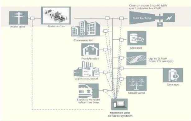
In Figure 1 is presented a visualization of the architecture of a micro grid with its distributed generation resources and monitor and control system with a coupling point to the main grid, suited between the main grid and the substation, to operate connected to the main grid or in off-grid mode. This presented microgrid consists on the left side, the loads (consumers): commercial buildings, residential area, light industry and supports a electric vehicle infrastructure to charge these vehicles.
Figure 1: A physical view of the Microgrid with its individual elements. Source: Adapted from DOHN, (2011).
2.1.1 MICROGRID CLASSIFICATIONS AND TYPES
Considering the operation states of microgrids, they can be classified into two: 1. Grid-connected mode microgrids
2. Island-mode microgrids
The grid-connected mode microgrids can operate connected to the main power grid or off-grid in island-mode also when there is a fault, maintenance, voltage or frequency drop on the main grid and it is disconnected from the main grid to supply energy to the customers during the time of electric energy interruption, (USTUN et al., 2011). However this type of operation requires complex control, communication and protection systems to fully isolate the micro grid from the main grid, while the utility grid operations can have a secured grid for maintenance or fault clearance operations without the fear of having an electrical energy reversed flow from a micro grid, (VACCARO et al., 2011).
According to research as mentioned by Hayden, (2013) and Siemens, (2011) there are five important microgrids types or market segments:
- Commercial and Industrial (C&I) MicroGrids
This type of microgrid (see Figure 2)is more found in north America and Asia Pacific and is comparable to the Campus and Institutional micro grid if includes one owner. This micro grid becomes very complicated if settled in a commercial or industrial region and involves various shareholders.
Figure 2: Industrial Microgrid. Source: Adapted from SIEMENS, (2011).
- Campus and Institutional MicroGrids
Figure 3: Campus/Institutional Microgrid. Source: Adapted from SIEMENS, (2011).
- Island and remote ‘‘off-grid’’ Micro Grids
This micro grid type (see Figure 4) is not connected to the utility grid and is usually located on islands or remote areas where a connection with the main grid is commonly absent and the aim is on distributed and various power sources. In the developing world these micro grids can get extended and transformed to micro grids connected to the main grid, while others keep their island-mode operation. These micro grids are the largest number of operational micro grid types nonetheless within villages with the lowest capacities.
- Community/Utility Micro Grids
This type of micro grid (see Figure 5) enhances the energy supply in residential areas, or even commercial and industrial areas. These micro grids can also be deployed in rural or urban communities that are grid-connected. Renewable or fossil-fueled distributed energy sources are mainly applied within these micro grids. There´s a large number of stakeholders in these micro grids, which makes processes complicated. They also do not operate in island-mode, which excludes them of the classic concept of a micro grid.
Figure 5: Utility microgrid. Source: Adapted from SIEMENS, (2011).
- Military Micro Grids
The main focus for employment of these micro grids is on reliability, and on physical and cyber security for military stations. Renewable energy sources are applied for fuel cost reduction and acquired power supply.
2.2 MICROGRID TECHNOLOGY
Microgrids have an identical structure compared to a conventional grid considering the power generation, distribution, transmission, and control features, only in a smaller scale than the main grid. At the same time, the microgrid technology is not identical to that of the conventional grid, due to their near load energy generation features, (HOSSAIN et al., 2014).
- Microgrid Control Systems
- Distributed Generation (DG)
- Islanding and Bi-Directional Inverters
- Smart Meters
- Distribution Automation (DA)
- Smart Transfer Switches
- Advanced Energy Storage
As mentioned by Hayden (2013), the most important technologies for improving the development of microgrids are: communication technologies, management systems for distribution and energy and sensors for control management.
A point of common coupling (PCC), which is the interconnection of a conventional grid and the distribution/generation side of a microgrid, is one of the main technologies required in a microgrid with both island mode and on-grid mode capabilities (see Figure 6). The microgrid technologies as mentioned earlier are hereby related to the different functioning units of the microgrid as presented in microgrid architecture Figure 6.
2.2.1 MICROGRID ENERGY GENERATION TECHNOLOGIES
The distributed energy generators (DG) are the energy generation units in the microgrids and there are two classifications known:
1. Renewable DG, such as: solar thermal, photovoltaic (PV), wind, hydro, biomass and biogas.
2. Non-renewable DG, such as diesel engine, stream turbine, gas engine.
In Table 1, is presented a summary of distributed generation technologies with their components, characteristics and costs. This table enhances a selection of the microgrid technologies in the functional unit of DG, where the electrical energy is being generated by these DGs from their different sources (renewable and non-renewable), (HOSSAIN et al., 2014).
2.2.2 MICROGRID ENERGY STORAGE TECHNOLOGIES
Energy storage is an essential element of microgrids. The energy storage technologies are mainly categorized as electrochemical systems (batteries and capacitor banks), potential energy storage (pumped hydro or compressed air storage), kinetic energy storage systems (flywheel energy storage) and fuel cells or traditional generators with their effectively large inertia. The energy storage cost of a microgrid is based on their reliability and resiliency requirements. With the necessity of energy storage in low-inertia power systems comes along the need for more advanced control systems for a robust system with adequate response times. Diminishing the amount of power conversions in microgrids is a system efficiency objective, hereby long-term investments in microgrid technologies are acquired for DC and hybrid (AC/DC) architectures to optimize the system efficiencies completely, (BOWER & REILLY, 2014).
In Table 2 is presented a summary of existing storage technologies. The batteries, flywheels and super capacitors are more appropriate for microgrid application. The reasons why these technologies are more adequate are:
- For energy reliability by ensuring sustainability of fixed voltage and frequency operation while using renewable energy sources, the energy storage systems based on batteries are the best solution.
There is a competition between storage systems with both batteries and flywheels in uninterruptible power supply applications, with regard to high power demands, power density and efficiency, (HOSSAIN et al. 2014).
Table 1: Distributed Generation Technologies of microgrids.
Source: Adapted from Hossain et al., (2014).
2.2.3 MICROGRID INTERFACE TECHNOLOGY
capable of controlling the voltage and frequency of a microgrid through respective control interfaces. The various functions of power electronics interface units are namely power conversion power conditioning (PQ), protection of output interface and filters, DER and load control, ancillary services, and monitoring and control. Power electronics are applied in microgrids for the objective of converting the features of electrical power such as voltage and current magnitude, phase and/or frequency to adapt to any specific utilization.
Table 2: A summary of existing energy storage technologies.
Table 3: A summary of power electronics conversion technologies.
Table 4: Summary of interface technologies of the microgrid.
Source: Adapted from Hossain et al., (2014).
2.2.4 MICROGRID SWITCH TECHNOLOGIES FOR INTERCONNECTION
disconnected from the main grid at the PCC (Point of Common Coupling), to operate as island or the other way around.
Microgrids usually have a rated peak power of less than 10MVA and their interconnection relay that interfaces the microgrid and utility service holds the great responsibility for success of transition management through the grid, by its switching control method (HOSSAIN et al. 2014). The various switch technologies and control technologies of microgrids are shown in summary in the Tables 5 and 6.
Table 5: A summary of the microgrid switch technologies.
Table 6: Analysis of the various control techniques in AC and DC microgrids.
Source: Adapted from HOSSAIN et al., (2014).
2.4 THE SMART MICROGRID
In the descriptions of smart microgrid in the literature, the smart grid with its features and technologies of the smart grid are always defined, because of their interconnection as described here.
The International Energy Agency, IEA (2011) has defined the smart grid as an upgraded electricity network which utilizes digital and other advanced technologies for monitoring and managing purposes of the electrical energy transport from the production source to the customers, to meet their demands.
There is a very close connection between the smart grid and the microgrid, based on the state of the art of technology of micro grids. Microgrids are interconnected with the smart grids; considered to be the basis or basic components of the ―macro‖ smart grid, allowing the implementation of the smart grid moderately/step by step, and introducing the development of interconnected distributed generation without doing harm to the main power system and offer new commercial agreements interest of the supplier/distributor and its clients. The microgrid and the smart grid are based on the same concepts to improve the interconnectivity of all components such as distributed generators with the focus on management and control, reliable energy, environmental issues and economy (de CASTRO, 2015).
(smart) micro grid´´. The smart micro grid network units used for smart grid developments make operating the network more accessible, because of the small scale power that has to be generated, transported and distributed (FARHANGI, 2010).
A main objective for smart microgrid systems is to accomplish promising new solutions by interconnecting smart microgrids in parallel with the utility distribution system and transitioning seamlessly to an autonomous power system complete with its controls, protection, and operating algorithms. It is expected that smart microgrids will be fielded in a wide variety of electrical environments ranging from substations to building-integrated systems, (BOWER & REILLY, 2014).
In Figure 7 is visualized a topology of an intelligent (smart) micro grid presented with a couple of possible distribution generators, advanced technologies and load profiles.
Figure 7: Topology of smart micro grid. Source: Adapted from Farhangi, (2010).
Since the concept of the Smart Grid had been introduced in 2001 by the U.S. Electric Power Research Institute, its popularity has kept increasing. The smart grid has been a driven factor in the battle to lower the carbon emissions and meet the exponential growing electricity demand. There is not one exact definition for the smart grid. The smart grid is defined in different ways across the countries, institutions and many researchers. What is well known among the many concepts of the smart grid, is that it´s mainly applied in the distribution network of the electricity grid, because that is the place where the most challenges of the existing electricity grid are. In the next part there will be mentioned a few of the many accepted definitions by researchers of the smart grid.
According to the Smart Grid 2013 Global Impact Report (2013), one of the accepted definitions of the smart grid is as follows:
monitoring, automation, control, co-ordination and inclusion of the transmission, distribution, generation (including distributed generation) and the demand side, for the purpose of increased energy and cost efficiency, sustainability, energy security as well as the benefit and empowerment of customers and society (LEWIS, 2013).’’
The US Department of Energy, DOE (2009), defines the Smart Grid as follows: ´´An automated, widely distributed energy delivery network, the Smart Grid will be characterized by a two-way flow of electricity and information and will be capable of monitoring everything from power plants to customer preferences to individual appliances. It incorporates into the grid the benefits of distributed computing and communications to deliver real-time information and enable the near-instantaneous balance of supply and demand at the device level´´.
The smart grid can be treated as a state-of the art electric power network framework for different matters such as advanced communication, sensing and metering systems, advanced energy information systems based on demand optimality aspects, advanced control systems and elevated efficiency (GÜNGOR et al., 2011).
The smart grid concept is described by Farhangi (2010), as the conjunction of the power system engineering with the ICT (information and communication technology). These are the basics of the smart technologies that are being applied to the current and future electricity networks.
If considered the many used concepts of the smart grid, it is definitely clear that they all have in common that the smart grid is an electricity grid which is a transformed electrical grid with new advanced technologies integrated with two-way communication technology to automate, control and manage all the units in the existing grid, especially the distribution of the electricity to the customers in the distribution network.
Figure 8: The main characteristics of a smart grid. Source: Rana & Li, (2015).
The smart grids are seen as modern grids that introduce state of the art technology into the existing electricity grid to integrate the electricity grid with information technology to get a better functioning, secure, reliable electricity network. The smart grids are also described as one of the important components for the sustainable energy future and there are many innovations in technology occurring based on ICT, electric Vehicles (EV), energy storage (batteries), wind solar and other distributed renewable energy sources and microgrids (MAH et. al., 2014).
With the focus on the challenges of the existing conventional electricity grid, we can consider the need for smart grids and thereby enhanced the need for smart microgrids, with their smart technologies such as advanced communication, automation, management and auto-repair technologies as a modern electrical grid (BUCHHOLZ & STYCZYNSKI, 2014).
Table 7: Smart grid technologies.
2.5 EXAMPLES OF (SMART) MICROGRIDS
As mentioned before, there are different types of microgrids. Of these microgrids the largest group of the microgrid type is the Institutional/Campus microgrid. Many of the Institutional/Campus microgrids are being employed for research matters and function as test-beds. As reported by many researchers of different institutions such as the IEA (The International Energy Agency), DOE (The U.S. Department of Energy), CERTS (The Consortium for Electric Reliability Technology Solutions), Lawrence Berkeley National Laboratories, and SANDIA National Laboratories, there are different microgrid experiments done to develop and keep the microgrids improving. Therefore research is done on the field of different strategies and technologies. These experiments or tests have different focuses for various reasons, such as commercial reasons or strictly R&D (Research & Development) goals (TURNER et al., 2015; LASSETER, 2010; MARNAY & BAILEY, n.d.; HUERTTA et al., 2014; SMITH, 2011; DOE, 2011; BOWER & REILLY, 2014; WHITAKER et al., 2008; GREACEN et al., 2013).
According to the summary report of the National Institute of Standards and Technology (NIST) in 2014, test-beds play an important role in smart grid, because they are essentially platforms for the rigorous and replicable testing of theories, new technologies, computational tools, and systems. The test-bed provides a development environment without the potential hazards or consequences present when testing in a live production environment. Test-beds in general can be used to demonstrate new components or entire systems, and can include software and hardware/physical equipment as well as networking components. Test-beds are especially important for evaluating performance and identifying any potentially adverse behaviors of interacting cyber-physical systems – before technologies are deployed in the smart grid. Smart grid test-beds can demonstrate ―hardware-in-the-loop‖ and integrated
cyber capabilities by combining real, simulated and emulated components or systems, creating an effective simulation of complex cyber-physical interactions in the power system (BOWER & REILLY, 2014).
microgrids are presented in Table 8 with their significant specifications such as distributed generation sources, total capacity, location.
Table 8: Several smart microgrids around the world.
Microgrid Name
Place/Country Microgrid type DGs Renewable
DGs Non-renewable
Capacity Storage
CERTS Ohio Residential; AC testbed No Gas Battery
Fort Carson U.S. base Colorado Spring
Military; Grid-tied PV;
Biomass; Thermal-Solar; Wind
Diesel 4MW --
NYU New York Campus; Grid-tied CHP Gas 13,4MW
BCIT Burbnaby Campus PV;
Thermal; Wind
No 555kW Battery
NEDO Japan Kyoto Grid-tied testbed PV; Wind Gas --- Battery
Osaka Plant Japan Osaka Campus; AC FC-CHP --- 300kW Battery
NTUA Athens Campus; Grid-tied PV; Wind Diesel 2,21kW Battery
Kythnos Greece
Gsidouro
Remote/´´Off-Grid´´; LV
PV Diesel 15kW Battery
Subax China Residential/Community;
Remote/´´Off-Grid´´
PV; Wind Gas;
Diesel
50kW Battery
Continuon’s MV/LV Holland plant The Netherlands
Utility; AC PV --- 315kW Battery
CSIRO Energy Center
Australia
Newcastle Utility; AC PV; Wind Gas 500kW Battery
Source: Elaborated by the author.
Several smart microgrids around the world
Of the several (smart) microgrids around the world as presented in Table 8, a few are further described in the next part to clarify their purpose of establishment.
North America:
(CERTS). The CERTS is a partnership between Northern Power Systems, S&C Electric Co, TECOGEN, AEP, Sandia National Laboratories and the University of Wisconsin. Their microgrids project includes various DGs and a thyristor based switch for grid disconnection in the off-grid mode. Their main goal was to search for a simple solution for operating grid-connected micro generation. The CERTS is responsible for the development and implementation of the microgrid concepts which reduces the microgrid field engineering tasks. These concepts are: a strategy for automatic and smooth transformation between island mode and grid connected mode, a microgrid protection process independent of high fault currents and a microgrid control arrangement for voltage and frequency stability with absent communication system (BARNES et al., 2007; HATZIARGYRIOU et al., 2007).
Fort Carson microgrid:
This is a military microgrid on a U.S. base in Colorado Springs of the SPIDERS (Smart Power Infrastructure Demonstration for Energy Reliability and Security) program. This extended base enhances an area of 550km2 and 14,000 habitants. The goal of this base is to become net zero facility, which means utility independent of the energy utility grid. A requirement of the microgrid is to perform during energy interruptions in island-mode to keep a part of the base operating (BOWER & REILLY, 2014)
New York University (NYU) microgrid:
This campus/institutional microgrid of the New York University (NYU), one of the largest universities in the United States, has been participating in the power producing sector since the 1960s and enhanced an extended oil-fired cogeneration plant in 1980. With the focus on microgrid they transformed to an advanced natural-gas combined heat and power (CHP) station at the end of their former (oil-fired) stations life-cycle for increased reliability and better managing of their energy expenses. The distribution area of electrical energy of this pant involves 22 buildings and the heat distribution area involves 37 building spread over the campus. This campus/institutional microgrid, NYU, is grid-connected to the Con Edison distribution grid and also has the capacity for functioning in island-mode, which had a favorable trial period during Hurricane Sandy (HAYDEN, 2013).
British Columbia Institute of Technology microgrid:
Japan:
Japan is recognized as the country with the most microgrid implementation projects around the world. They are dedicated to introducing more RE systems into their distribution system and this could bring harm to their utility power system. These RE systems are usually wind and PV systems of an irregular nature. To solve these challenges the microgrids are introduced of which most projects are funded by the NEDO, New energy and Industrial Technology Development Organization, and started around 2005. Examples are the Kyoto eco-energy microgrid testbed which is connected to the utility grid trough a substation. This microgrid enhances gas engines, a battery bank, two PV systems, a wind turbine, remote monitoring and control system and communication systems (HATZIARGYRIOU et al., 2007).
European Union:
Reduction of carbon emissions by 2020 is high on the agenda of the European member states since they have one of the highest levels of global warming and climate change alertness which has resulted in the promotion of increased utility of renewable energies and reduction of energy demand by increasing the energy efficiency. The ―Microgrids project‖, was the first EU funded microgrid project managed by the National Technical University of Athens (NTUA). This project was established with the focus on the dynamics of DGs in microgrids and the develop methods for various matters such as security, control algorithms and definition of DG interface response and advanced (smart) concerns (HATZIARGYRIOU et al., 2007).
Other examples of microgrids are a pilot project in Greece on the Kythnos Island, ISET microgrid in Germany with the focus on an extensive study on control applications, the microgrid at Seville on the university of Seville Spain that is based on PV arrays, Fuel cells and battery banks (lead acid) for storage. Their communication and control system is based on SCADA and PLC (Programmable Logic Control). There are also smaller scale microgrids projects of the EU such as the Continuon Holiday Camp Microgrid in the Netherlands
(USTUN et al., 2011; HATZIARGYRIOU et al., 2007).
2.5.1 SMART MICROGRIDS IN BRAZIL
operational efficiency; expansion and automation of the electric power system with standardized smart technologies; reduction of non-technical losses; improvement of the system reliability and power quality, especially for industries and high-tech based companies (PICA et al., 2011).
There has been an association established by the Ministry of Minas and Energy (MME) between the EPE (Empresa de Pesquisa Energéticas), the CEPEL (Centro de Pesquisas de Energia Elétrica), ANEEL (Agência Nacional de Energia Elétrica and the ONS (Operador Nacional do Sistema Elétrico). This association will have their focus on public political matters for implementing smart grids and management studies to control the introduction of new elements in the electric grid system such as microgrids, (de CASTRO, 2015).
The main challenges concerning the introduction of smart grid in the energy sector of Brazil are mainly the remote areas like the rural areas and the Amazon; illegal connected energy loads, the size of the Brazil energy matrix, reliability standards and legislatives of the energy sector. The smart grid in Brazil is mainly achieved through the enhancement of smart metering by distribution companies to expand the efficiency in operation with remote meter data transmission and reduction of the energy commercial losses (PICA et al., 2011).
Examples of smart grid enhancing smart microgrid concerns in Brazil, implemented by several companies, research centers and universities are (FALCÃO, 2010):
– ONS (Operador Nacional do Sistema Elétrico) Implementation of PMUs (Phasor Measurement Units) project: studies for the installation of PMUs units at strategic points of the national interconnected system with the objective, among others, to improve the disturbance capacity and state estimation; and monitoring the electrical system for connecting electrical islands and closing loop and oscillations monitoring;
– UFSC (Universidade Federal de Santa Catarina) MEDFASEE Project: is smart microgrid project based on synchronized phasor measurement system consisting of units located in several Brazilian university campuses and connected to the low voltage network, able to monitor the functioning of the Brazilian electrical system;
– Measurement Systems Automated Deployment projects by Light, Wide, Eletropaulo and Cemig: several electricity distribution companies in the country have been executing the implementation of centralized systems of electronic measurement.
– COPPE / UFRJ (Instituto Alberto Luiz Coimbra de Pós-Graduação e Pesquisa de Engenharia/ Universidade Federal de Rio de Janeiro) Microgrid projects: is campus smart microgrid that involves the implementation of an experimental microgrid, consisting of various alternative sources of small size, with the objective to study control schemes, automated metering and protection; PMU Applications in System Security: Online detection of voltage collapse proximity.
2.6 MODULAR DESIGN APPROACH FOR THE SMGP
The perception of modularity has gained interest of engineers, management researchers and corporate planners in various utilities in the last decennia. Modularization of a product or process is described as the separation of components which are then committed to modules conform a precise arrangement or method.
Modularization has three objectives from an engineering view: 1. To allow simultaneous activity.
2. To control complexity. 3. To adapt concerns to come.
Modularity adapts concerns because the specific components of a modular design may be adjusted or alternated suddenly, but has to be according to the design guidelines (BALDWIN & CLARK, 2004).
2.6.1 THE MODULAR DESIGN METHOD
Eggen (2003 apud FLEIG, 2008) defines the concept of modularity as a method used by companies as an alternative to their product range at the same time it facilitates the traditional mass production that turns into mass customization. In the opinion of this author, there is no guide to determine the best modularity method to be followed by a company. Modularity is a tool to break the structure of the product in small but manageable units, and thus make mass customization possible. A module is structurally independent building block, which is part of a large system with well defined interfaces. The module is connected to the rest of the system in a way that development can occur independently.
is defined as a strategy to systematize complex designs and process operations effective by breaking up complex systems into smaller blocks. Hereby the designer can be admitted to work with joint collections of components to evolve and produce a great number of products (JOSE & TOLLENAERE, 2005). In the engineering literature several definitions for the terminology involved with modular design are found and presented in the Table 9.
As defined by Clark and Baldwin (2004), the compatibility between modules is
guaranteed by ―design guidelines‖ that control the architecture, the interfaces and the
patterned test of the system. The process of modularizing a system includes the three functions:
- Defining its architecture: means the existence of the modules, what they are
- Defining its interfaces: the way the modules communicate or connect
- Defining tests: to make sure that the modules will interact together and each will be functioning great
Table 9: Definitions for ´´modularization´´ from the engineering literature.
Author Definition
Galsworth, 1994 A module is a group of standard and interchangeable components.
Wilhelm, 1997 A module is a complex group that allocates a function to the product and which could be changed and replaced in a loose way and be produced independently.
Baldwin and Clark, 1997 A modular system is made of independent units which can be easily assembled and which behave in a certain way in a whole system.
Huang and Kusiak, 1998 The term modularity is used for the expression of common and independent parts for the creation of a variety of products.
Source: Adapted from Jose and Tollenaere, (2004).
As mentioned earlier by Baldwin and Clark (2004), the modularity in the design of a complex system permits modules to undergo transformations in the future, without undermining the purpose of the complete system. Hereby is pointed out that the modular design of a complex system is permissive to uncertainty and accepts experimentation in the modules.
The connection between people and products is defined by the way they design, produce and use them. Therefore modularity comes down to three basic types:
design of the system is modular. It is only modular-in-design if the process of designing it can be divided and shared over independent modules, which are related to design guidelines, not by continuous agreements between the designers.
2. modularity-in-production: Just like modular-in use systems, this type depends on designs that are tightly coupled and centrally controlled. It is used for many years by industries like for example automobile industries. The production of different parts of the automobile is done in various sites and brought together to assemble the final product. This is possible due to their precise guidelines for the way the different parts must be connected together to assemble a specific vehicle and for the utilities that provide the parts to follow the engineering specifications such as dimensions, tolerances, functionality etc.
3. modularity-in-use: Is a system of goods in which customers can combine different elements together to have a desired finish. For example, customers frequently purchase things like bed frames, covers, mattresses, linens of various manufacturers and distributors, which all adapt together because they are made in common sizes. Modularity-in-use accommodates customization of the system to please the customer. Concluded is that modularity-in-design is less assumed and has the most appealing economic results in comparison with other modularity types. The reason lies in the fact that new designs are essentially options with associated economic option value. Modularity-in-design accumulates the alternatives built in a complex system. Increase of the total economic value of the system and transforms the manners how the system can develop are both additional results, (BALDWIN And CLARK, 2004).
Ulrich and Eppinger (2012) described the product architecture of modular design as the event where the physical components are related to functional elements to form different products. These two dimensions in the architecture are defined as follows:
1. The functional one, which is the selection of activities and alterations that supplies to the general functionality of the product.
2. The physical one, which indicates to the selection of physical components and assemblies that facilitates a function.