Angle Class II, Division 2, malocclusion with
deep overbite
Paulo Renato Carvalho Ribeiro*
This case report describes the orthodontic treatment of an adult patient, who presented a Angle Class II, Division 2, malocclusion, with overbite, severe curve of Spee, right maxil-lary lateral incisor proclined and gengival recessions. The patient was treated with extrac-tion of the first premolars and maximum anchorage control. This case was presented to the Brazilian Board of Orthodontics and Dentofacial Orthopedics (BBO) representing the category 6, deep overbite malocclusion, as part of the requirements for obtaining the title of Diplomate by BBO.
Abstract
Keywords: Angle Class II malocclusion. Corrective Orthodontics. Deep overbite.
* Specialist in Orthodontics and Facial Orthopedics, Rio de Janeiro State University (UERJ). Professor at the Course of Specialization in Orthodontics and Facial Orthopedics, Brazilian Dental Association (ABO) Juiz de Fora (MG). Graduate from the Brazilian Board of Orthodontics and Facial Orthopedics.
HISTORY AND ETIOLOGY
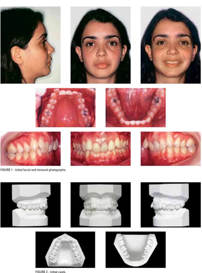
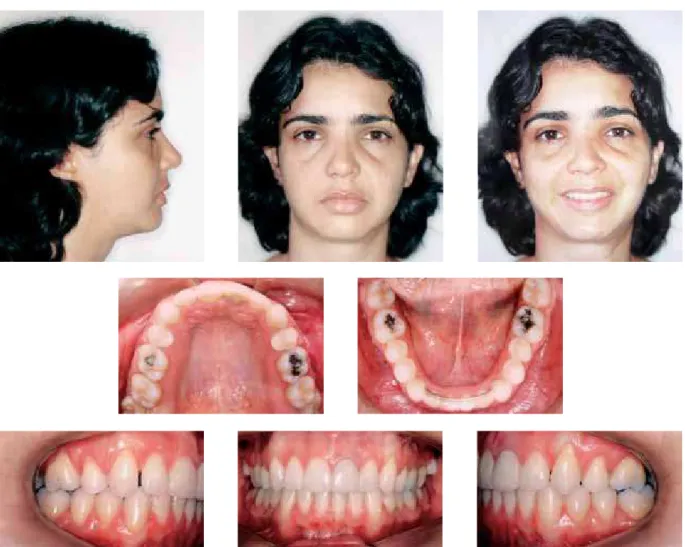
The patient presented for initial examination at the age of 24 years and 7 months in good gener-al hegener-alth and no history of serious illness or injury. Her main complaint was related to the fact that the incisors were malpositioned with significant-ly altered axial inclination. The patient reported having undergone endodontic treatment in the upper left central incisor and had extensive resin restorations in the anterior teeth. No orthodontic treatment had hitherto been performed.
DIAGNOSIS
The patient presented with an Angle Class II, Division 2 malocclusion, a 100% overbite, sharp retroclination of teeth 11, 21 and 22, and labio-version of tooth 12. The upper dental arch con-tained extensive restorations in the central inci-sors, some recession, especially in the first molars,
and crowding. The lower arch exhibited adequate alignment, but with a pronounced Curve of Spee (Figs 1 and 2).
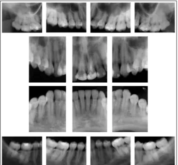
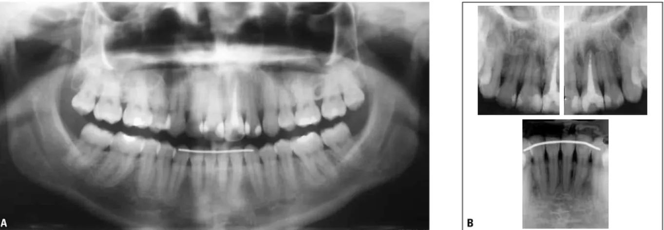
An analysis of the periapical radiographs dis-closed an endodontic treatment in tooth 21 and reassured the author that the patient did not pres-ent with any condition that might compromise the orthodontic treatment (Fig 3). The side profile X-ray and cephalometric tracing showed: Incisor uprighting (1-NA = 0°); Class II skeletal pattern, ANB angle = 5º, (SNA = 80° and SNB = 75º) and normal mandibular growth in the vertical orienta-tion (SN-GoGn = 32°, FMA = 23º and Y-axis = 60°). This information can be viewed in Figure 4 and Table 1.
FIGURE 4 - Initial cephalometric radiograph of side profile (A) and cephalometric tracing (B).
A B
FIGURE 3 - Initial periapical radiographs.
TREATMENT GOALS
Considering that this is an adult patient with a harmonious facial profile, the author attempted to maintain the vertical, transverse and antero-posterior position of the bone bases. As regards
while maintaining the intercanine and intermo-lar widths. Thus, it was anticipated that upon treatment completion correct guides would be achieved for the canines with adequate overbite and overjet, promoting a significant improve-ment in smile esthetics.
TREATMENT PLAN
To achieve the proposed goals the patient was informed that the treatment plan involved the extraction of the first upper premolars. In the following step, an orthodontic appliance was fixed to the upper arch teeth (Standard Edgewise system, slot 0.022 x 0.028-in), a headgear and transpalatal arch were fitted and round stainless steel 0.014 to 0.020-in arch wires were used for alignment and leveling of the posterior segments. To enable the alignment of the upper anterior teeth, the canines were moved slightly distally using sectional arch wires (T loops). At the same time a Ricketts5,6 utility arch wire was made from round stainless steel and used to correct the overbite and projection of the upper incisors. Whenever possible, based on this projection of the upper incisors, the orthodontic appliance was bonded to the lower arch and a series of 0.014 to 0.020-in straight arch wires installed for lev-eling. For anchorage control the use of Class II mechanics was also planned, in case it proved necessary. After moving the upper canines dis-tally the incisors were retracted using rectangu-lar 0.019 x 0.025-in stainless steel arch wires, with vertical loops between the lateral incisors and canines. The cases were finished using upper and lower 0.019 x 0.025-in arch wires with indi-vidual bends, as needed. Upon completion of the active treatment, the author used, as planned, an upper removable wraparound retainer made of 0.036-in stainless steel wire, and on the lower arch, an intercanine retainer using 0.032-in wire. The patient was duly instructed, verbally and in writing, about the necessary cares in handling the retention appliances, as well as their oral hygiene.
TREATMENT PROGRESS
FIGURE 5 - Final facial and intraoral photographs.
completion of space closure, the upper arch was re-bonded for re-leveling with 0.014 to 0.020-in stainless steel wire. The treatment was completed using ideal stainless steel 0.019 x 0.025-in arch wire on the upper and lower arches and the use of Class II elastics. Third molar extraction was pre-scribed. After ensuring that all the intended goals had been achieved the orthodontic appliance was removed and the retention phase began. To this end, we used a removable upper wraparound re-tainer, made with stainless steel wire 0.036-in and a lower retainer with round wire 0.032-in bonded
to teeth 33 and 43. The patient was recommend-ed to wear the upper retainer 24/7 for the first year and after that period, twelve hours a day for six months, and finally, just nights for another six months. The lower intercanine retainer was pre-scribed indefinitely.
TREATMENT RESULTS
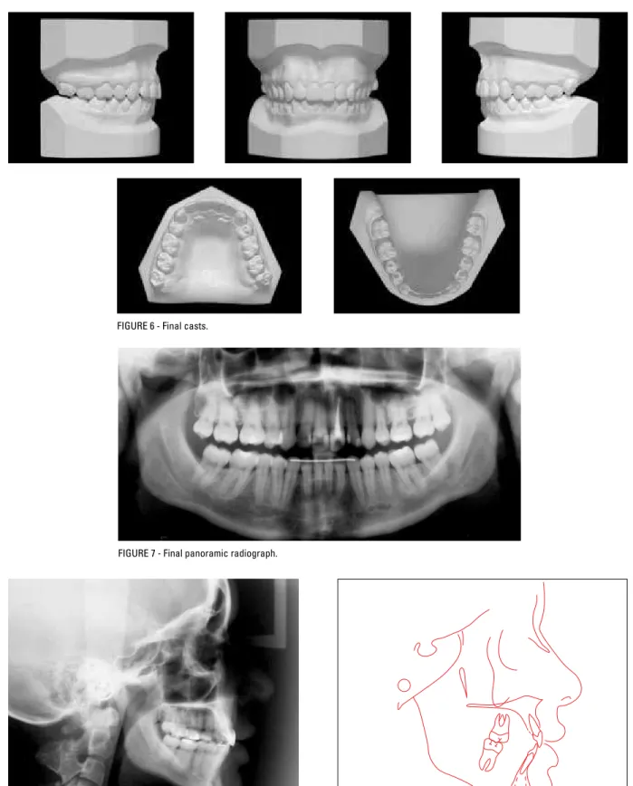
FIGURE 6 - Final casts.
FIGURE 7 - Final panoramic radiograph.
FIGURE 8 - Final cephalometric radiograph of side profile (A) and cephalometric tracing (B).
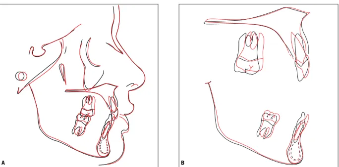
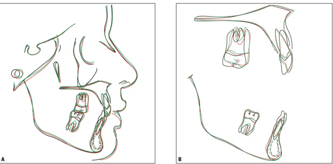
FIGURE 9 - Total (A) and partial (B) superimposition of initial (black) and final (red) cephalometric tracings. B
A
anteroposterior change reflected in the slight movement of point A, due to the correction of incisor inclination. This resulted in a Class I skel-etal pattern with the ANB angle changing from 5º to 4º. As can be seen in Table 1, the 1-NA angle underwent a major change from 0° to 16° and the linear positioning of the incisors (1-NA, mm) increased by 2 mm, increasing from 2 mm to 4 mm. This change was made to allow overbite correction, considering that the initial retroclina-tion precluded intrusion owing to the proxim-ity of the incisors’ root apex to the cortical bone of the maxilla. The intercanine and intermolar widths were maintained (Table 2).
In the mandible, there was no change in the position of the bone base. There was an increase in incisor inclination, as can be seen in Table 1, re-flected in alterations in the 1-NB measurements (from 14º to 26º) and the IMPA angle (from 87º to 98º). Thus, the interincisal angle underwent a significant change from 161º to 135º. Similarly to the maxilla, the intercanine and intermolar
widths remained unchanged (Table 2).
An analysis of the panoramic radiograph (Fig 7) revealed adequate root parallelism, except in the region between the upper lateral incisor and canine on the right hand side and between the lower canine and first premolar on the same side. There was also a slight apical blunting of the upper incisors, compatible with the significant movement performed in these teeth.
FIGURE 13 - Control cephalometric radiograph (A) and cephalometric tracing (B) - three years and four months after treatment completion.
A B
FIGURE 12 - Panoramic (A) and periapical (B) control radiographs of incisors acquired three years and four months after treatment completion.
A B
Tests obtained three years and four months after the end of the corrective orthodontic treat-ment period (Figs 10 to 14) demonstrated that such positions remained stable. Upon treatment completion, the aesthetic rehabilitation had not
FIGURE 14 - Total (A) and partial (B) superimposition of initial (black), final (red) and control (green) cephalometric tracings - three years and four months after treatment completion.
B A
TABLE 1 - Summary of cephalometric measurements.
MEASUREMENTS NORMAL A B A-B DIFFERENCE C
SKELET
AL P
A
TTERN
SNA (Steiner) 82° 80° 79° 1 79º
SNB (Steiner) 80° 75° 75° 0 75º
ANB (Steiner) 2° 5° 4° 1 4º
Convexity Angle (Downs) 0° 7º 4° 3 6º
Y-axis (Downs) 59° 60° 61° 1 61º
Facial Angle (Downs) 87° 85° 84° 1 83º
SN – GoGn (Steiner) 32° 32° 32° 0 33º
FMA (Tweed) 25° 23° 25° 2 26º
IMPA (Tweed) 90 ° 87° 98° 11 96º
DENT
AL P
A
TTERN
1 – NA (degrees) (Steiner) 22° 0° 16° 16 15º
1 – NA (mm) (Steiner) 4 mm 2 mm 4 mm 2 4 mm
1 – NB (degrees) (Steiner) 25° 14° 26° 12 24º
1 – NB (mm) (Steiner) 4 mm 3 mm 6 mm 3 6 mm
1
1 – interincisal angle (Downs)
130° 161° 135° 26 136º
1 – APo (mm) (Ricketts) 1 mm 0 mm 3 mm 3 2 mm
PROFILE
Upper Lip - S Line (Steiner) 0 mm 1 mm 0 mm 1 0 mm
Submitted: October 2009
Revised and accepted: December 2009
TABLE 2 - Measurements of transverse distances on the dental arches (mm).
MEASUREMENTS A B A - B Difference C
Intercanine width
Upper 34.5 mm 34.5 mm 0 34.5 mm
Lower 26 mm 26 mm 0 26 mm
Intermolar width
Upper 47 mm 47 mm 0 47 mm
Lower 43 mm 43 mm 0 43 mm
FINAL CONSIDERATIONS
Angle Class II, Division 2 malocclusion is characterized by retroclination of central incisors usually associated with a pronounced overbite. To correct this anomaly in adult patients profes-sionals often rely on the extraction of first pre-molars. This procedure, as in our case, requires adequate anchorage control to ensure an appro-priate relation between the canines. The treat-ment described in this study shows that—even in the face of compliance issues regarding the patient’s use of headgear—thanks to ongoing re-sult assessment and a timely change in mechanics (in this case, the author resorted to the Burstone sectional arch mechanics) it is possible to keep anchorage under control by means of specific biomechanical principles2-7 and thus achieve the goals laid down at the start of treatment. The cor-rection of severe overbite was performed by a set of well-planned tooth movements that initially included the projection of the upper incisors by means of an uncontrolled tipping movement so
as to allow the apex of these teeth to move away from the labial cortex. Only then was intrusion performed, as required, with the aid of a round Ricketts5,6 utility arch.
Contact address
Paulo Renato Carvalho Ribeiro Rua Oswaldo Cruz, 75 – Santa Helena CEP: 36.015-430 – Juiz de Fora / MG E-mail: [email protected] 1. Andrews LF. The six keys to normal occlusion. Am J Orthod.
1972 Sep;62(3):296-309.
2. Burstone CR. Deep overbite correction by intrusion. Am J Orthod. 1977 Jul;72(1):1-22.
3. Burstone CJ, Koenig HA. Creative wire bending: the force system from step and V bends. Am J Orthod Dentofacial Orthop. 1988 Jan;93(1):59-67.
4. Nanda R. Biomechanics in clinical Orthodontics. 9ª ed. Philadelphia: W. B. Saunders;1997.
REFERENCES
5. Ricketts RM. Bioprogressive therapy as an answer to orthodontic needs. Part I. Am J Orthod. 1976 Sep;70(3):241-68.
6. Ricketts RM. Bioprogressive therapy as an answer to orthodontic needs. Part II. Am J Orthod. 1976 Oct;70(4):359-97.
7. Strang R. Tratado de Ortodontia. 3ª ed. Buenos Aires: Bibliográfica Argentina;1957.