Mestrado Integrado em Engenharia Química
Development of Nanomaterials using the
NETmix® Technology:
Application to Production of MOFs
Tese de Mestrado
desenvolvida no âmbito da unidade curricular de
Dissertação
Marcelo Filipe dos Santos Costa
LSRE-FEUP
Departamento de Engenharia Química
Orientadores na FEUP: Prof. José Carlos Lopes Profª. Madalena Dias
“Simplicity is the ultimate sophistication.” Leonardo Da Vinci
Agradecimentos
Em primeiro lugar, gostaria de agradecer a todas as pessoas que me foram acompanhando, não só na realização da dissertação de Mestrado, mas ao longo de todo o curso e de toda a vida.
Gostaria de agradecer particularmente a algumas pessoas, que quer pelo seu apoio incondicional, quer pela sua paciência, me ajudaram e contribuíram de forma muito positiva para a minha evolução.
Em especial, gostaria de agradecer aos meus orientadores, o Professor José Carlos Lopes e a Professora Madalena Dias, pelas condições dadas para o desenvolvimento da tese, num tema tão atual e importante. Agradecer também por todo o apoio e disponibilidade demonstrada ao longo das semanas de trabalho.
Gostaria também de agradecer ao Eng. Carlos Fonte, pela incansável paciência e apoio que me deu durante o desenvolvimento do trabalho.
Ao Professor Joaquim Faria, gostaria de agradecer pela ajuda na caracterização físico-química do material.
Gostaria de agradecer a toda a equipa com quem trabalhei, pela boa disposição e bom ambiente. Em especial, ao Eng. Mumin Leblebici, colega no laboratório E404B e aos Engs. Cláudio Fonte e Marina Torres pela ajuda nas experiências de reologia.
Ao Eng. Luís Carlos pela realização dos ensaios de densidade e à Engª. Liliana Pereira pelo auxílio na realização dos ensaios de absorção atómica.
Ao Institut Lavoisier, em especial à Doutora Patricia Horcajada e Doutor Thomas Devic pelo pronto esclarecimento das dúvidas que foram surgindo ao longo do trabalho.
Para finalizar, gostaria de agradecer aos meus colegas de curso, que durante 5 anos tiveram que lidar com o meu mau feitio e embirrações. Agradecer também a todos os meus amigos, que foram muito importantes nesta caminhada que agora termina.
Não podia deixar de agradecer a toda a minha família, em especial aos meus pais e ao meu irmão, muito do que alcancei deve-se a eles.
Declaração
Declaro, sob compromisso de honra, que este trabalho é original e que todas as contribuições não originais foram devidamente referenciadas com identificação da fonte.
Marcelo Filipe dos Santos Costa Julho de 2012
Abstract
The production of nanoparticles, particularly MOFs, has been widely studied for several applications in several areas. The production of MOFs is not trivial. Several factors need to be taken into account and many parameters need to be controlled in order to obtain a material that can be used in a certain application.
In the present work, NETmix capabilities were tested for the production of MIL-88A, a metal-organic framework built up from iron (III) trimers linked to fumarate ligands, creating a 3-dimensional flexible network. The influence of concentration, temperature, addition of a dispersant and the maturation step on the particle size and shape were studied.
It was observed that the maturation step is important when production occurs at room-temperature, due to the formation of a possible metastable phase. When the experiment is performed at 80 ºC, although the final phase is immediately observed, the particles are larger. Significant differences between NETmix and batch productions were not verified, except when operated at higher temperatures. NETmix® has shown capacity to produce MOFs under continuous flow production.
The material phase transition is a phenomenon that needs to be well understood in future works.
Keyword: Nanoparticle, Metal-organic framework, crystallization,
Resumo
A produção de nanopartículas, nomeadamente os MOFs, tem sido amplamente estudada para uso em várias aplicações em diferentes áreas. A produção de MOFs não se trata de um processo simples. São vários os fatores que têm de ser tidos em consideração e são muitos os parâmetros que necessitam de ser controlados de forma a se obter um material que possa ser usado numa determinada aplicação.
No presente trabalho, as capacidades da tecnologia NETmix foram testadas para a produção do MIL-88A, um MOF criado através de trímeros de ferro (III) ligados a cadeias de fumarato, que formam uma rede tridimensional e flexível. A influência da concentração, temperatura, adição de um dispersante e a etapa de maturação no tamanho e forma das partículas foi estudada.
Observou-se que a maturação é particularmente importante quando a produção ocorre à temperatura ambiente, devido à inicial formação de uma possível fase metastável. Quando as experiências são realizadas a 80 ºC, apesar de se obter imediatamente a fase desejada, observa-se que as partículas são maiores. Não foram verificadas diferenças significativas entre as produções com o NETmix e batch, exceto quando operados a temperaturas mais elevadas. O NETmix® mostrou-se capaz de produzir MOFs em modo contínuo.
Table of contents
1 Introduction ... 1
1.1 Motivation and Relevance ... 2
1.2 Thesis Objectives and Layout ... 2
2 State of the Art ... 4
2.1 Introduction ... 4
2.1.1 Synthesis routes ...5
2.2 Potential Applications of MOFs ... 9
2.2.1 Hydrogen and methane storage ...9
2.2.2 Gas adsorption selectivity ... 10
2.2.3 Catalysis in MOFs ... 11
2.2.4 Drug storage and delivery ... 11
2.2.5 Other applications ... 12 2.3 MIL-88A ... 12 2.4 NETmix® Reactor ... 17 3 Technical Description ... 20 3.1 Experimental Set-up ... 20 3.2 Characterization ... 23 3.2.1 Rheological experiments ... 23
3.2.2 Scanning Electron Microscopy (SEM) and Energy Dispersive Spectroscopy (EDS) ... 25
3.2.3 Dynamic Light Scattering (DLS) ... 26
3.2.4 Electrophoresis (Laser Doppler Velocimetry) ... 26
3.2.5 Atomic Absorption spectroscopy ... 27
3.2.6 X-Ray Diffraction (XRD) ... 27
3.2.7 Differential Scanning Calorimetry (DSC) and Thermogravimetric (TG) analysis ... 27
3.2.8 Nitrogen Adsorption ... 28
3.2.9 Helium Picnometer Method and Mercury Porosimetry ... 28
4 Results and Discussion ... 29
4.2 Iron (III) conversion ... 32
4.3 Particles size distributions ... 34
4.4 SEM and EDS analysis ... 36
4.5 XRD Results ... 40
4.6 Specific surface area ... 41
4.7 Thermal analysis ... 42 4.8 Density ... 43 5 Final Remarks ... 45 5.1 Conclusions ... 45 5.2 Future Work ... 45 5.3 Global Appreciation ... 46 References ... 47
Rheology experiments’ results ... 49
Appendix A SEM images ... 53
Appendix B Shear rate and geometrical dimensions of the NETmix® reactor ... 66
Appendix C Nanoparticles mean free path ... 68
Appendix D Amount of dispersant ... 71 Appendix E
Notation
a diagonal length (see Appendix D) m
A NETmix® channels cross section area m2
C concentration mol/L (M)
d NETmix® channels depth m
D NETmix® chambers diameter m
H
D hydraulic diameter m
d isp
D dispersant molecule diameter m
I edge length (see Appendix D) m
j diagonal length (see Appendix D) m
L particles length m
m mass g
M molecular weight g/mol
n number of moles mol
N number
A
N Avogadro number mol-1
Q volumetric flowrate m3/s
R e Reynolds number
R I refractive index
B E T
S specific surface area by BET method m2/g
T temperature ºC V volume m3 W particles width m X chemical conversion y direction’s position m Greek letters x
distance between two nanoparticles m
shear rate s-1 r Dielectric constant ex p experimental porosity th eo r theoretical porosity m ean
mean zeta potential mV
diffraction angle º
viscosity Pa∙s or cP
velocity m/s
density kg/m3
NETmix® channels width m
Indexes 0 initial ap apparent disp dispersant F e iron max maximum m in minimum n p nanoparticles reac reactants
s o l solution
t time instant
x direction
List of Acronyms
BASF Badische Anilin und Soda Fabrik bdt 1,4-benzeneditetrazolate BET Brunauer-Emmett-Teller BTC 1,3,5-benzenetricarboxylate
CEMUP Centro de Materiais da Universidade do Porto DLS Dynamic light scattering
DMF N,N’-dimethylformamide
DSC Differential scanning calorimetry EDS Energy-dispersive X-ray spectroscopy
HKUST Hong Kong University of Science and Technology IBU Ibuprofen
INA Isonicotinate
IRMOF Isoreticular metal-organic framework
ITQMOF Instituto de Tecnologia Quimica metal-organic framework LCM Laboratório de Catálise e Materiais
LDV Laser doppler velocimetry MIL Matériaux de l’Institut Lavoisier MOF Metal-organic framework MRI Magnetic resonance imaging PCN Porous coordination network PVP Polyvinylpyrrolidone
SBU Secondary building unit SEM Scanning electron microscopy
TG Thermogravimetry
XRD X-ray diffraction
List of Tables
Table 1. Cell parameters of the MIL-88 type structures [28]. ... 13
Table 2. Series of experiments. ... 23
Table 3. Initial pH values and mean zeta potential for different dilution factors. ... 31
Table 4. BET surface area of sample N01. ... 42
Table 5. Densities and porosities of MIL-88A. ... 43
List of Figures
Figure 1. General building scheme for MOFs [8]. ...2 Figure 2. A tentative hierarchy of coordination polymers and metal-organic frameworks; adapted [17]. ...4 Figure 3. Overview of synthesis methods, possible reaction temperatures and final products [7]. ...5 Figure 4. Scheme of the Ostwald ripening process. ...6 Figure 5. Catenation example of MOF PCN-6: (a) – Catenated PCN-6; (b) Non-catenated PCN-6 [23]. .. 10 Figure 6. Hydrogen, oxygen, nitrogen and carbon monoxide adsorption isotherms of PCN-13 at 77 K [25]. ... 11 Figure 7. Ibuprofen delivery ((a): % IBU; (b): mg IBU/g dehydrated material versus time for MIL-100 and MIL-101 [5]. ... 12 Figure 8. Trimer of MIL-88. Yellow: iron atoms; Red: oxygen atoms; black: carbon atoms [8]. ... 13 Figure 9 – Structures of the MIL-88 based topology: (a) MIL-88A (experimental); (b) MIL-88B
(simulation); (c) MIL-88C (simulation); (d) MIL-88D (simulation). Left: along the a axis; Right: along the c axis [28]. ... 13 Figure 10. Molecular structure of MIL-88A trimer (each iron is bonded to the oxygen atom of water). Green: iron atoms; Red: oxygen atoms; black: carbon atoms. ... 14 Figure 11. Experimental X-ray powder diffraction of MIL-88A, dried (423 K) as-synthesized (no post-treatment) or wetted with various solvents [30]... 15 Figure 12. Simulated crystal structures of MIL-88A in its dry (left), as-synthesized (no post-treatment - center) and open (right) forms [31]. ... 15 Figure 13. Particle size (curves) and yield (bars) as a function of time using different solvents [18]. . 16 Figure 14. TEM images obtained from hydrothermal microwave synthesis of MIL-88A at various
temperatures and synthesis times [18]. ... 16 Figure 15. (a) Schematic representation of a network of chambers and channels; (b) 2D unit cell; (c) 3D unit cell [12]. ... 17 Figure 16. NETmix® prototypes: (a) NETmix® 3D; (b) Lab-Scale NETmix® 2D; (c) Multi-Inlet NETmix® 2D. ... 18 Figure 17. Tracer experiments at Re=150 [12]. ... 18 Figure 18. Pre-mixed injection scheme [12]. ... 20 Figure 19. NETmix® reactor experimental apparatus. Legend: 1-NETmix® Reactor; 2-Feeding pumps; 3-Reactants vessels; 4-Final product flask. ... 21
Figure 20. Batch experimental apparatus. Legend: 1-Batch reaction vessel; 2-Peristaltic pump;
3-Reactants vessel. ... 21
Figure 21. Schematic of the rheological experiments procedure. ... 24
Figure 22. Maximum viscosity of the reaction mixture as a function of the shear rate at 25 °C. ... 25
Figure 23. Electrical layers of the surface particles [34]. ... 27
Figure 24. pH variation with time in the ageing stage. ... 30
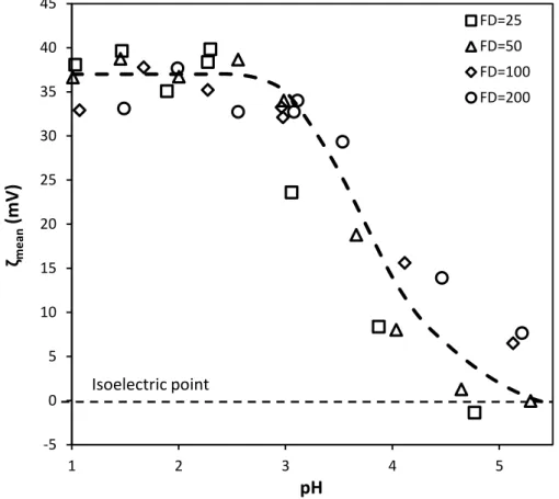
Figure 25. Zeta potential measurements: mean zeta potential as a function of pH. Isoelectric point is the point where the zeta potential is zero. ... 31
Figure 26. Zeta potential distributions for different pHs. ... 32
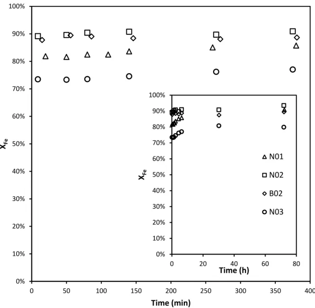
Figure 27. Iron conversion as a function of time, during the ageing stage. ... 33
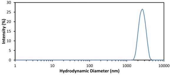
Figure 28. Particle size distribution of sample N01 after 72 hours of maturation. ... 34
Figure 29. Particles size distribution of samples B02 (after 72 hours of maturation), N02 (after 72 hours of maturation) and N02 (dried, no maturation). ... 35
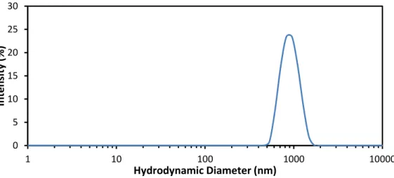
Figure 30. Particle size distribution of sample N03 after 72 hours of maturation. ... 35
Figure 31. Particle size distribution of samples B04 and N04, both after 72 hours of maturation. ... 36
Figure 32. SEM image of sample N01 (72 hours). ... 36
Figure 33. SEM images of samples N02 and B02: (a) N02 (0 hours); (b) N02 (72 hours); (c) B02 (0 hours); (d) B02 (72 hours). ... 37
Figure 34. SEM images of sample N03: (a) 0 hours; (b) 72 hours. ... 38
Figure 35. SEM images of samples: (a) N04 (0 hours); (b) B04 (0 hours). ... 38
Figure 36. SEM image of sample B05 (72 hours). ... 39
Figure 37. SEM images of non-mature samples after several days: (a) N02; (b) B02; (c) N03. ... 39
Figure 38. Sample N03 (after 72 hours of maturation) with indication of the tested region. ... 40
Figure 39. EDS spectrum for the region presented in Figure 38. ... 40
Figure 40. X-Ray diffraction spectra for N02, B02 and B05 samples. ... 41
Figure 41. Adsorption and desorption isotherms of nitrogen for different degassing conditions: (a) ) 150 ºC for 3 hours; (b) 100 ºC for 5 hours; (c) 100 ºC for 20 hours. ... 41
Figure 42. DSC and TG results of sample N01. ... 43
Figure A-1. Reaction mixture viscosity as a function of time for different shear rates (for reactants concentration = 0.4 M). ... 49
Figure A-2. Reaction mixture viscosity as a function of time for different shear rates (for reactants concentration = 0.16 M). ... 50
Figure A-3. Reaction mixture viscosity as a function of time for different shear rates (for reactants
concentration = 0.08 M). ... 50
Figure A-4. Maximum viscosity as a function of: (a) reactants concentration; (b) shear rate. ... 51
Figure A-5. Influence of the dispersant in the viscosity increase (shear rate = 356.5 s-1). ... 52
Figure B-1. SEM images of sample N01, at different scales. ... 53
Figure B-2. SEM images of sample N02, no maturation, at different scales. ... 54
Figure B-3. SEM images of sample N02, no maturation, after several days, at different scales. ... 55
Figure B-4. SEM images of sample N02, after 72 hours of maturation, at different scales. ... 56
Figure B-5. SEM images of sample B02, no maturation, at different scales... 57
Figure B-6. SEM images of sample B02, no maturation, after several days, at different scales. ... 58
Figure B-7. SEM images of sample B02, after 72 hours of maturation, at different scales. ... 59
Figure B-8. SEM images of sample N03, no maturation, at different scales. ... 60
Figure B-9. SEM images of sample N03, no maturation, after several days, at different scales. ... 61
Figure B-10. SEM images of sample N03, after 72 hours of maturation, at different scales. ... 62
Figure B-11. SEM images of sample N04, no maturation, at different scales. ... 63
Figure B-12. SEM images of sample B04, no maturation, at different scales. ... 64
Figure B-13. SEM images of sample B05, no maturation, at different scales. ... 65
Figure C-1. Parabolic velocity profile in a NETmix® channel. ... 66
Figure D-1. Nanoparticles geometry. ... 68
Figure D-2. Volume of the solution with nanoparticles. ... 69
1 Introduction
Recently nanosized particles have gained attention from materials specialists due to their unique properties, which can be applied in the development of novel products to be used in numerous applications. Metal-organic frameworks are a good example of the growing interest in this type of materials.
Metal-organic frameworks, MOFs, are crystalline coordination networks consisting of metal ions or clusters linked by organic ligands to form porous or non-porous structures (Figure 1), depending on whether the networks allow access of guest molecules or not. The choice of the metal and the linker has significant effect on the final structure of the MOF, size and shape of the pores.
Since their discovery in 1989 [1], Metal-organic framework materials have attracted extensive attention due to their potential in a wide range of applications. MOFs have shown promising potential for gas adsorption and separation, hydrogen and carbon dioxide storage and catalysis [2, 3]. There are some promising results in biological imaging, luminescence sensing and drug delivery [4, 5].
Traditionally, the porous materials that have been used are either organic (e.g. activated carbon) or inorganic (e.g. zeolites). Organic materials are disordered structures. Inorganic materials require an organic or inorganic template (with strong interactions with the inorganic framework) for its synthesis, which can lead to a collapse of the material. The combination of both organic and inorganic structures in metal-organic frameworks results in stable and ordered materials, with high surface areas [6].
MOFs are usually synthesized by combining organic ligands and metal salts in solvothermal (or hydrothermal, depending whether the solvent is water or not) reactions, where the reactants are mixed in an autoclave, at temperatures up to 300 ºC [7]. The reactants are usually mixed in polar solvents such as water, ethanol, dialkylformamides, dimethyl sulfoxide or acetonitrile. The solvents not only dissolve reactants but also play a role as structure directing agents, which influence the properties of the final MOF. Alternative routes for MOFs synthesis have been developed and described in literature, including the mixture of non-miscible solvents, electrochemical route, and microwave irradiation [7].
The number of possible combinations between the metal ions and the organic ligands is extremely high, leading to a wide variety of different materials with different applications (many of them still unknown), so it is an ungrateful task any attempt to quantify them.
Figure 1. General building scheme for MOFs [8].
1.1 Motivation and Relevance
The production of high-value nanoparticles, such as metal-organic frameworks materials has gained particular interest over the last 2 decades, due to the possibility of obtaining a large variety of structures of interest for several fields related to porous materials.
In this work, the NETmix® static reactor has been tested to produce the metal-organic framework MIL-88A (designed by the Institut Lavoisier Versailles, Paris). MIL-88A exhibits a 3-D structure built up from trimers of iron (III) octahedral linked by fumarate chains [9].
The NETmix® reactor is a static mixer [10] that has a high degree of macro and micromixing quality control along the reactor. It is a new technology consisting of a regular network of cylindrical chambers (well mixed zones) and rectangular cross-section channels (segregation zones) [11-13]. This reactor has been successfully used to produce high purity, single-phase, nanocrystalline hydroxyapatite, with the stoichiometric amount of Ca/P ratio (important for its applications)[14, 15].
Mixing is one of the more important steps in the chemical industry. In many cases, deficient mixing conditions lead to deficient products. In nanomaterials, such as MIL-88A, the particle size is strongly dependent of the mixing conditions [16]. Therefore, it is essential to achieve good mixing (both macro and micromixing) to smooth out supersaturation peaks in local regions [16].
The motivation of this work is to revolutionize the metal-organic frameworks synthesis techniques, using lower temperatures, achieving higher productivities and a better control of its physical properties, using the NETmix® reactor.
1.2 Thesis Objectives and Layout
The main objective of this work is to study the properties of the metal-organic framework MIL-88A, synthesized using the NETmix® reactor at room temperature.
The layout of this work is as follows.
As a result of bibliographic research, Chapter 2 contains the state-of-the-art on metal-organic frameworks, particularly MIL-88A. In this chapter, some theoretical concepts about the physical process of crystallization are reviewed. Some important issues about MIL-88A are introduced, such as its main applications, synthesis routes used in previous works and its particular properties. Moreover, the NETmix® technology is introduced and its advantages are analyzed.
The technical description of the experiments will be presented in Chapter 3, such as the experimental set-up and description of the techniques used for particle characterization. The obtained results are presented and discussed in Chapter 4, along with some of the technical difficulties faced along the project.
The mains conclusions of this work are presented in Chapter 5. Also, a full evaluation of the project, including future improvement suggestions, is given.
2 State of the Art
2.1 Introduction
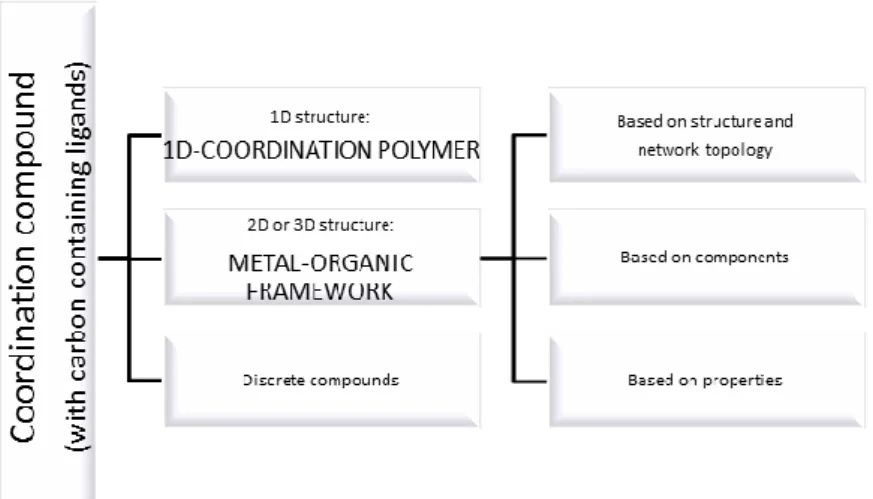
Metal-organic frameworks, MOFs, are among the research areas of most interest in organic chemistry and materials engineering. MOFs are crystalline materials constituted by metallic ions connected by organic chains, called linkers (or ligands). Yet, it is extremely complicated to completely define what is and what is not a metal-organic framework [17]. Particularly, the nomenclature of these materials is still under question due to the difficulty of two different sciences (chemistry and material science) being able to produce the same kind of materials, but yet refer to them by different names. For example, coordination polymers and metal-organic frameworks are different names for the same type of materials (see Figure 2). Another question is what is a metal-organic framework? A porous material? Or simply a 3-dimensional structure made from metallic salts? In a recent classification [17] the following definition has been proposed: a metal-organic framework is any system that forms a 2D or 3D network with carbon containing ligands bridging mononuclear, polynuclear or 1D coordination entities.
Figure 2. A tentative hierarchy of coordination polymers and metal-organic frameworks; adapted [17].
Thus, the concept of metal-organic framework will be used, in this work, because it is the most widely used nomenclature for these materials.
The synthesis of MOFs has attracted immense attention in the last couple of decades, because the combination of compounds and the number of different structures is almost infinite. Those structures have shown great potential for applications in a number of fields related to porous materials, including storage, separation and catalysis [3].
Although the number of possible structures is extremely large, the specialists give their attention to a small fraction of MOFs. To speed up the discovery of MOFs, high-throughput methods have been developed.
There are a huge number of different methods, with different operational conditions to synthesize MOFs. Figure 3 summarizes the main methods for MOFs production.
Figure 3. Overview of synthesis methods, possible reaction temperatures and final products [7].
Although different methods exist, it does not mean that a certain MOF can be produced by all of the methods described in Figure 3. Moreover, the same reaction mixtures can lead to different structures depending on the method that was used [7]. The method from which the MOF is synthesized may have a strong impact on reaction time, yields, particle size distribution and morphology. This is due to the complexity of the crystallization process, that requires appropriate kinetics to allow nucleation and growth of the desired MOF phase [7]. The implementation in large-scale processes is another complicated topic, regarding particles crystallization.
2.1.1 Synthesis routes
As mentioned before, there are a great number of different processes to create MOFs. Those processes involve different conditions and can be suitable for the production of some MOFs and not suitable for others. Reaction temperature is one of the most important parameters in MOFs synthesis [7].
Usually the process is divided into two different conditions: solvothermal and nonsolvothermal. Solvothermal reactions take place in closed vessels under autogenous pressure above the boiling point of the solvent, while nonsolvothermal reactions take place below or at the boiling point under ambient pressure [7].
The early works on this subject focused on the traditional crystallization techniques, such as precipitation. Precipitation is a widely used industrial process and is particularly important for the production of pharmaceuticals, paints and some polymers [16]. Precipitation often implies an irreversible process of crystallization. These processes are usually initiated at high supersaturation, resulting in fast nucleation and small growth rate of the crystals. Precipitation consists of three different physical stages, which are supersaturation, nucleation and growth (common to all crystallization processes), followed by two secondary steps, agglomeration and ageing. Theoretically, the mix of two reacting solutions should be enough to precipitation to occur. Nevertheless, nucleation does not necessarily initiate as soon as the reactants are mixed. It is crucial to understand all the trade-offs of this process. Supersaturation conditions, temperature, efficiency of mixing, intensity of agitation, presence of impurities are important factors that have to be taken into account [16].
One of the main difficulties of creating small particles is that the particles in suspension have a tendency to cluster together, in a process called agglomeration (aggregation, coagulation, flocculation are also used terms). Agglomeration occurs due to the collisions of particles, small enough for the van der Waals forces to exceed the gravitational forces.
The ageing stage is a process that covers all irreversible changes that take place in a precipitate, after its formation. One of the processes that occur in ageing step is the Ostwald ripening (proposed by Wilhelm Ostwald in 1896), which is a process where the small particles dissolve over time, and the solute redeposit onto larger particles, with the purpose to achieve a minimum total surface free energy (thermodynamically more stable) (Figure 4) [16].
Figure 4. Scheme of the Ostwald ripening process.
In this process, the small particles disappear and the large particles continue to grow and the particles size distribution may become narrower.
Another important ageing process is the first-precipitation of a metastable phase followed by a phase transformation to the final product. This metastable phase may be an amorphous precipitate, or a polymorph of the final product.
For metal-organic frameworks production, the widely used precipitation technique is by direct mixing. A common method for producing a precipitate is to mix two reactant solutions together as quickly as possible. By definition, crystallization by precipitation involves a highly controlled supersaturated medium and it is extremely difficult to maintain uniform conditions of supersaturation throughout the reaction vessel. This means that the mixing quality is very important.
Some MOFs have been obtained from nonsolvothermal conditions (even room-temperature) by just mixing the raw materials (using a precipitation process), such as 5, 74, MOF-177, HKUST-1 or ZIF-8. Some of these MOFs (e.g. ZIF-8) show good thermal and chemical stabilities [7].
Chemical reactions often require some form of input of energy (either for solvothermal or nonsolvothermal conditions). This energy is generally introduced to the system by conventional electric heating, i.e., heat transferred from a hot source through convection. The different characteristics of the energy source may influence the final product and its morphology. Some alternative means of heating the reaction medium have been tested, such as electric potential, electromagnetic radiation, mechanical waves or by mechanical work [7, 18].
One of the most used processes is the energy supply by microwave irradiation, which is a well-established method in synthetic chemistry, but used mainly in organic chemistry [7]. Microwave-assisted synthesis relies on the interaction of electromagnetic waves with mobile electric charges. These charges can be polar solvent molecules/ions or electrons/ions in a solid. When the electromagnetic field is applied, and electric current is produced, the heating occurs due to the resistance of the solid (Joule effect). In solution, the polar molecules try to align in an electromagnetic field and in an oscillating field, so that the molecules constantly change their orientations, thus increasing their kinetic energy (and temperature) [7]. Microwave-assisted synthesis of MOFs has often been carried at temperatures above 100 ºC and reaction times not exceeding 1 hour. In general, irradiation of microwaves allows faster synthesis of smaller crystals, compared to conventional heating. The electrochemical synthesis of MOFs was first reported in 2005 by researchers of BASF [7], with the purpose of excluding anions, such as nitrate, perchlorate or chloride, during the synthesis. Rather than using metal salts, the metal ions are continuously introduced through anodic dissolution to the reaction medium containing dissolved linker molecules and a conducting salt. The metal deposition on the cathode is avoided by using protic solvents,
forming H2. The main advantage of this technique is the absence of both oxidant and
reducing agents, which makes the final purification easier. Another advantage of the electrochemical route is the possibility of obtaining higher solids content, in a continuous process, compared to normal batch processes. Studies with this method have been done mainly with the mesoporous iron(III) trimesate MIL-100(Fe) and the microporous copper trimesate KHUST-1 [19]. It is a very simple method that takes place at atmospheric pressure. The energy source can be a mechanical force that induces physical phenomena as well as chemical reactions. In simple terms, in this process, the intramolecular bonds are mechanically broken, allowing chemical transformation. This technique is well-known in synthetic chemistry, and has been employed in pharmaceutical industry, organic synthesis and polymer synthesis. Its use for synthesizing MOFs was first reported in 2006, producing the metal-organic framework C u IN A 2 [20]. Other structures like HKUST-1 or MOF-14 [7] have been synthesized by this technique. There are several advantages of this method. One of them is the possibility of producing solvent-free metal-organic frameworks, which is important in an environmental point of view. Short reaction times (in the range of 10-60 min) lead to reasonable yields and small particles.
Metal-organic frameworks can also be produced through sonochemical synthesis [7]. Sonochemistry is a technique that delivers ultrasound energy to the reaction medium. Ultrasound is a mechanical device that produces vibration with a frequency in the range 20 kHz and 10 MHz. The high-energy ultrasound interacts with liquids, alternating zones of high pressure with zones of low pressure – acoustic cavitation. In the low pressure regions, the pressure is lower than the vapor pressure of the solvent and the reactants, allowing small bubbles to be formed [21]. These oscillating bubbles can accumulate ultrasonic energy while growing (solute vapor diffuses into the bubbles). Under certain conditions, the bubble will grow until the critical size is achieved. In that point, the bubble collapses, releasing the stored energy, creating extreme conditions (temperatures of 5000 K and pressures of 1000 bar) that can result in chemical interactions between the reactants. It is important to state that the chemical reaction is not promoted by direct interactions of the ultrasound waves due to the fact that the wavelength is much larger than molecular dimensions. The primary goal of sonochemical synthesis in MOF chemistry was to find a fast, energy-efficient, environmentally friendly method, at room-temperature that can easily be carried out. Some studies have been done regarding the synthesis of metal-organic frameworks using ultrasound waves, producing MOFs such as IRMOF-9 and 10, MOF-5, MOF-177, MIL-53, MIL-88A and HKUST-1 [7].
The combination of different metal ions, organic ligands, solvent and synthesis method (as well as operational conditions) may result in an almost infinite number of different structures.
2.2 Potential Applications of MOFs
Metal-organic frameworks, as other porous materials (like zeolites or activated carbon), are very useful in gas storage, gas/vapor separation through adsorption phenomena, shape/size-selective catalysis, drug storage and delivery, and as templates in the preparation of low-dimensional materials. In this section, some of these applications will be discussed.
2.2.1 Hydrogen and methane storage
A tank charged with a porous adsorbent enables a gas to be stored at a much lower pressure than an identical tank without adsorbent. The fact that high pressure storage is not necessary using adsorbents provides safer (and more economical) gas storage. There are several studies of adsorbents for gas storage such as activated carbon, carbon nanotubes or zeolites. The growing interest of studies regarding the possibility of using metal-organic frameworks for gas storage it is due to its unique characteristics (tunable pore geometries and flexible frameworks) [2, 3, 22].
Hydrogen is an excellent energy carrier, due to its high combustion energy (almost 120 MJ/kg). Yet hydrogen is extremely hard to store in its gas state. Even to store hydrogen in liquid state, very low temperatures are required, as well as high pressure [3].
The current hydrogen storage techniques involve the use of high pressure tanks, cryogenic tanks, chemisorption and physiosorption. However, any of these techniques show limiting disadvantages that turn them unviable. MOF-5 was first used in 2003 for hydrogen storage [22]. Since then, almost 150 other MOFs have been tested. The storage of hydrogen in MOFs is due to van der Waals interactions between the hydrogen and the metal-organic framework (physical adsorption). The main advantage of MOFs for this purpose is the great surface area that presents (e.g. MOF-177 has a BET surface area of 4500 m2/g). However the adsorption of hydrogen is only significant at low temperatures (77 K), which means that increasing the interactions between the MOF and hydrogen is crucial, which can be done changing the structure and geometry of the metal-organic framework. Catenation, when two or more identical frameworks interpenetrate each other could be used to generate MOFs with appropriate pore sizes, enhancing the interactions and the hydrogen adsorption capacity of the adsorbent (Figure 5) [23, 24].
Natural gas is another great energy carrier. Its main component is methane (>95%), while the rest is a mixture of ethane, other hydrocarbons, nitrogen and carbon dioxide. Its heat of
combustion is 50 MJ/kg (higher than gasoline, but lower than hydrogen). Nevertheless, its use is limited due to storage-related difficulties. Adsorption of methane is possible and several studies have been performed to analyze the use of MOFs such as MIL-53, PCN-11, PCN-14 or HKUST-1 for methane storage [7].
Figure 5. Catenation example of MOF PCN-6: (a) – Catenated PCN-6; (b) Non-catenated PCN-6 [23].
2.2.2 Gas adsorption selectivity
Adsorption is the main phenomenon that occurs between the surface of a solid and a fluid. Adsorption can have chemical properties, when there is bond formation between the solid and the fluid, or only physical properties, when the interactions are due to the van der Waals forces. With the ever-increasing demand for more environmentally friendly industrial applications, the use of mainly physical adsorption as a separation process of gases in chemical engineering has been higher than ever [7]. A mixture of gases can be separated by two mechanisms: different equilibrium with the adsorbent or different kinetics. Therefore, the selectivity of the adsorbent for an adsorbate is very important. The selectivity (as well as the capacity) of the adsorbent is dictated by its chemical composition and structure.
The principal mechanisms based on which selective gas adsorption is achieved in MOFs are adsorbate-adsorbent interactions (chemical or physical) and size-exclusion (molecular sieving effect). Selective gas based on sized-exclusion has been successfully shown with several MOFs, such as PCN-13 or PCN-17, for separation of O2 and N2 [7]. PCN-13 contains a square
channel of 3.5 Å3.5 Å [7]. The larger the size of the N2 molecule (kinetic diameter of 3.64
Å) as opposed to the O2 molecule (diameter of 3.46 Å) completely prevents the nitrogen from
entering the channels, while allowing oxygen to pass through the pores, meaning that the adsorbed volume of O2 is higher than the volume of N2 (Figure 6).
Cu(bdt) is another MOF that can separate O2 from N2 due to different interactions between
these two components and the solid [7].
There has also been described some dynamic and flexible MOFs that allow the separation of gases via size-exclusion mechanisms or due to different interactions [7].
2.2.3 Catalysis in MOFs
As porous materials, MOFs may prove themselves useful in catalysis. Besides the high metal content of MOFs, one of their greatest advantages is that the active sites are rarely different because of the highly crystalline nature of metal-organic frameworks. The selectivity of MOFs as catalysts is achieved by the size or shape of the material that depend on the porosity and the presence of active transition-metal centers. Yet, only a few examples of MOFs have been reported for their use in catalysis [7].
Figure 6. Hydrogen, oxygen, nitrogen and carbon monoxide adsorption isotherms of PCN-13 at 77 K [25].
2.2.4 Drug storage and delivery
Drug delivery is a method of administering a pharmaceutical compound to achieve a certain therapeutic effect. Drug delivery technologies modify the drug release profile and absorption, making it more convenient for the patient. Essentially, the developed delivery systems are classified into organic systems and inorganic systems. Organic systems have the advantage of having good biocompatibility and the ability to uptake many drugs. The inorganic delivery materials have the advantage of delivering the drugs at a controlled rate, due to their ordered porous network. Metal-organic frameworks are, as mentioned before, hybrid materials, i.e., have inorganic and organic properties, presenting themselves as optimal drug-delivery materials. However, the main problem of using MOFs for this purpose it that the small pore size (in the micro-range) limits the uptake or the number of drug molecules that can be stored within the framework. MOFs with mesopores (2 nm – 50 nm) need to be created for its use in drug delivery. MIL-100 and MIL-101 have shown to be suitable for drug delivery, due to their well-defined, ordered porosity (Figure 7) [5].
The difference observed in Figure 7 can be explained by the size of ibuprofen (6 Å10.3 Å) which is able to fit in both pentagonal (12 Å) and hexagonal (16 Å) windows of MIL-101, but not into pentagonal window of MIL-100 (4.8 Å) [5].
2.2.5 Other applications
Metal-organic frameworks possess other interesting properties that can be used for a wide variety of other applications, not listed above. For instance, the magnetic properties that MOFs present can be very useful. In fact, magnetic nanoparticles can be important in several applications, such as tumor targeted drug delivery, tumor ablation [26], magnetic separation, magnetic hyperthermia and MRI contrast enhancement [27]. The potential applications of MOFs depend on their behavior under the action of an external magnetic field, which depend on the intrinsic nature of the metal and the organic ligand, as well as the structure as whole. However, more studies in this area are required.
(a) (b)
Figure 7. Ibuprofen delivery ((a): % IBU; (b): mg IBU/g dehydrated material versus time for MIL-100 and MIL-101 [5].
Another potential application of MOFs is in the luminescence and sensors area. Luminescent materials can be prepared by combining the luminescent metal ions or clusters and organic ligands, as well as special guest molecules [3]. Metal-organic frameworks that possess luminescent properties together with size or shape-selective sorption can be used as sensing devices of ions (e.g. MOF-76), guest/solvent molecules (e.g. Eu(BTC)) or anisotropic photoluminescence probes (e.g. ITQMOF-1 and ITQMOF-2).
2.3 MIL-88A
The number of possible associations between inorganic moieties and organic linkers to form hybrid inorganic-organic porous materials is very large. In this work, a particular MOF was chosen, MIL-88A, a MOF developed and synthesized at l’Institut Lavoisier, a research institute from the Université de Versailles in France. MIL is the acronym used in MOFs produced at this laboratory.
MIL-88 [9] exhibits a 3D structure built up from trimers of iron (III) octahedral linked to organic anions to create a 3D framework. MIL-88 presents trimers containing 3 iron (III) atoms sharing a μ -O3 atom (the center atom in Figure 8). Each iron atom share, with other iron atom, an organic linker molecule. For 88A, the organic ligand is fumarate, while for MIL-88B is terephthale, for MIL-88C is 2,6-naphthalenedicarboxylate and for MIL-88D is 4,4’-biphenyldicarboxylate. These 4 structures have in common the iron octahedral trimer shown in Figure 8. As the structure in Figure 8 links to each other, they form the so-called Secondary Building Units (SBUs).
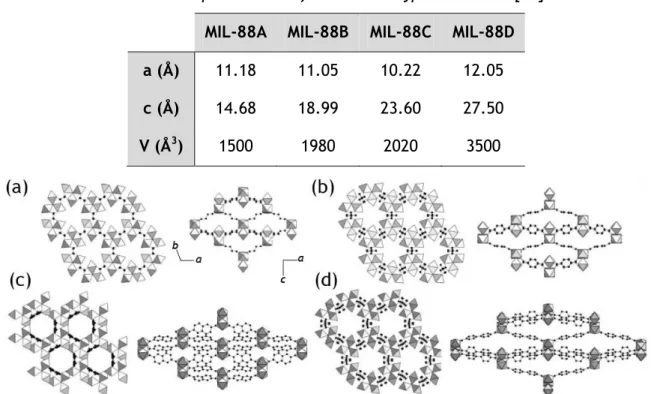
Figure 8. Trimer of MIL-88. Yellow: iron atoms; Red: oxygen atoms; black: carbon atoms [8]. Table 1 lists the cell parameters of the 4 types of MIL-88 and Figure 9 shows the predicted structures of these materials.
Table 1. Cell parameters of the MIL-88 type structures [28]. MIL-88A MIL-88B MIL-88C MIL-88D
a (Å) 11.18 11.05 10.22 12.05
c (Å) 14.68 18.99 23.60 27.50
V (Å3) 1500 1980 2020 3500
Figure 9 – Structures of the MIL-88 based topology: (a) MIL-88A (experimental); (b) MIL-88B (simulation); (c) MIL-88C (simulation); (d) MIL-88D (simulation). Left: along the a axis; Right:
The structure of MIL-88A delimits both a 1D pore-channel system along the c axis, which is filled with solvent molecules, and cages [9]. The free solvent molecules that are present within the pores interact through hydrogen bonds with oxygen atoms of the organic trimers. Also, van der Waals interactions between the solvent and the structures are predictable. The chemical formula of MIL-88A is
3 + μ III -3 2 3 4 2 4 3 2 Fe O H O C H O nH O O H (other anion) (2.1)The 3 molecules of water present in the structure may change, depending on the used solvent, but each molecule of solvent gives one of its oxygen atoms to the trimer structure. The counter ion of MIL-88A is mainly hydroxide (from water), but may be any other anions present in solution.
The fumarate chains, represented by the black circles in Figure 10, are responsible to bond with other trimers, creating the porous framework of MIL-88A.
Figure 10. Molecular structure of MIL-88A trimer (each iron is bonded to the oxygen atom of water). Green: iron atoms; Red: oxygen atoms; black: carbon atoms.
MIL-88A has a density of 1.55 g/cm3, corresponding well to the simulated density which is 1.73 g/cm3 [9]. It usually presents a bimodal distribution of sizes [29]. The average pore size is about 6 Å [29].
The possible flexibility of MIL-88A has also been assessed [30, 31] indicating a very large swelling capacity upon post-synthesis treatments. In fact, the flexibility of metal-organic frameworks comes from their host-guest interactions. The change of the solvent, as well as the post-synthesis treatments (such as drying) also revealed differences in the crystalline structure of the network [30].
As can be observed in Figure 11, the XRD spectrums show different crystalline structures in each situation. This experimental information was useful to predict the structure, through computational simulations (Figure 12).
The synthesis methods of MIL-88A have been the subject of further development [18]. Some techniques listed above were used to produce this metal-organic framework, such as typical solvothermal (or hydrothermal) synthesis into a Teflon-lined steel autoclave, autogenous pressure synthesis, ultrasound and microwave synthesis.
Figure 11. Experimental X-ray powder diffraction of MIL-88A, dried (423 K) as-synthesized (no post-treatment) or wetted with various solvents [30].
Figure 12. Simulated crystal structures of MIL-88A in its dry (left), as-synthesized (no post-treatment - center) and open (right) forms [31].
The effects of synthesis methods, solvents (dimethylformamide, ethanol, methanol or water), reaction time and temperature were studied with regard to particles size and yield [18]. The reactants to produce MIL-88A were iron (III) chloride hexahydrate and fumaric acid. The influence of adding acetic acid or sodium hydroxide was also studied. The use of alcohols as solvents decreased the reaction kinetics, due to competitive reactions (formation of fumaric acid ester), using a solvothermal approach [18]. Nevertheless, when pH was up to 2.7 by addition of sodium hydroxide, MIL-88A was obtained in methanol. Larger particles were
obtained when methanol or water is used as a solvent (probably due to the lower solubility of fumaric acid in these solvents, when compared with DMF). When water is used as solvent, it was observed that the particles size increased over time while the yield remained constant (which may be an indication of aggregation or ripening). Using methanol or DMF, both the particles size and yield increased with time (Figure 13).
Figure 13. Particle size (curves) and yield (bars) as a function of time using different solvents [18].
It was also observed that the particles size increased with temperature (Figure 14), as well as the yields, meaning that higher temperatures promote the nucleation and growth of the particles. It was also observed that acetic acid worked as an inhibitor, while the addition of sodium hydroxide increased the reaction kinetics, which may indicate a significant influence of the pH over the crystallization phenomena of MIL-88A.
Figure 14. TEM images obtained from hydrothermal microwave synthesis of MIL-88A at various temperatures and synthesis times [18].
The microwave method presented very promising results. As can be observed in Figure 14, the rod-shaped MIL-88A is only obtained after a while (10 minutes at 80 ºC). The obtained yields were always above 40 % using the microwave assisted synthesis.
MIL-88A was chosen to test the properties of the existing NETmix® due to its synthesis simplicity (simply by mixing a fumarate source and an iron (III) source). This metal-organic framework can be synthesized in nonsolvothermal conditions (temperatures under 80 ºC) and at ambient pressure, enabling the production in the existing NETmix® reactor.
2.4 NETmix® Reactor
The main purpose of this work is the production of nanoparticles of MIL-88A at low temperatures and without recurring to high pressures, using the NETmix® technology.
NETmix® is a patented [10] new type of static mixer/reactor where mixing can be controlled effectively and efficiently making it particularly suited for complex and fast kinetics reactions. It consists of a network structure that combines two different types of elements (chambers and channels), organized in a 2D network [11, 12]. Networks are generated by the repetition of unit cells where each unit cell consists of one chamber and two inlet and two outlet channels oriented at a 45º angle from the main flow direction (Figure 15a) and can either be constructed from cylindrical chambers and rectangular cross section area channels (2D unit cell, Figure 15b) or from spherical chambers and cylindrical channels (3D unit cell, Figure 15c).
(b) (c)
(a)
Figure 15. (a) Schematic representation of a network of chambers and channels; (b) 2D unit cell; (c) 3D unit cell [12].
To date, three prototypes were built for different purposes. The NETmix® 3D was the first prototype ever built and was constructed from two acrylic slabs where half chambers and channels were imprinted and then glued together (Figure 16a).
The Lab-scale NETmix® 2D was built for lab-scale projects with lower throughputs and was the reactor used along this work for the production of MIL-88A (Figure 16b). When larger throughputs are needed, the Multi-Inlet NETmix® 2D is used (Figure 16c). This prototype incorporates multi-inlet injection points along the reactor.
The transition to the 2D configuration represents a considerable decrease on the construction complexity since only one of the slabs has the chambers and channels imprinted. The two
slabs are no longer glued together allowing the disassembling and cleaning of the reactor, being insulation made by mechanical aperture and o-rings.
(a) (b) (c)
Figure 16. NETmix® prototypes: (a) NETmix® 3D; (b) Lab-Scale NETmix® 2D; (c) Multi-Inlet NETmix® 2D.
Laranjeira [12] observed that above a critical channel Reynolds number, the flow inside the mixing chambers evolves to a self-sustained oscillatory flow regime inducing local strong laminar mixing.
The Reynolds number in the NETmix® channels,
Re
, is defined asR e DH
=
(2.2)
where is the mixture’s density (kg/m3), is the average velocity in the channels (m/s),
H
D is the hydraulic diameter of the channels (m) and is the viscosity (Pa·s).
Homogenization in the chamber is almost instantaneous when the mixing dynamics is higher [12] (Figure 17). For this reason, chambers can be assumed to behave as perfectly mixing zones and the channels as plug flow perfect segregation zones.
Figure 17. Tracer experiments at Re=150 [12].
Many of the existing continuous reactors used for nanoparticles production overcome the difficulty of controlling the mixing conditions by scaling down. The issue with downscaling is
the reduction of reactor throughput, and for that reason high volume production of nanoparticles is one of the major challenges for process engineers nowadays.
NETmix® links the control of mixing in the small basic units, channels and chambers, with large throughputs that are achieved by repeating the basic units as many times as necessary. It has already been shown to be a promising industrial technology to produce nanoparticles with high reproducibility, mainly in terms of size distribution [14, 15], where the control of the stoichiometry of the reactants and micro and macromixing are key factors and was successfully used in hydroxyapatite nanoparticles production [14, 15], with high reproducibility, mainly in terms of size distribution.
In summary, the advantages of NETmix® in comparison to other static mixers are [14, 15]:
Simple structure;
Easy implementation of different pre-mixing reactants injection schemes;
Ability to control residence time and to control mixing intensity and scale;
Easy inclusion of temperature, pressure and concentration controls without modifying its dynamics;
Large area promotes heat exchange, that can be used in temperature control;
3 Technical Description
3.1 Experimental Set-up
The main purpose of this work is to use all the capabilities of NETmix® for metal-organic frameworks productions. To do this, two different experimental set-ups were assembled: continuous flow reaction in NETmix® followed by ageing in a stirred flask and a batch reaction in a stirred flask with ageing in the same vessel.
The NETmix® reactor used in this work is a small unit, made of stainless steel and acrylic, with total volume of 22.9 mL, with 29 rows and 8 columns (more information in Appendix C). The reactants were distributed through the inlets following a pre-mixed scheme (Figure 18).
Figure 18. Pre-mixed injection scheme [12].
The reactants are fed to the NETmix® reactor by two pumps (Ismatec BVP-Z Standard). The final product is discharged to a flask under stirring where it ages for 72 hours (Figure 19). In batch set-up (semi-batch to be more accurate), one of the reactants is placed on the stirred tank reactor (1 L), while the other is introduced in the system by a peristaltic pump (Ismatec MCP) (Figure 20). In order to ensure similar conditions, the flowrate of the peristaltic pump was chosen to take the same amount of time as the experiment in the NETmix® reactor. The reactant was injected directly above the stirrer blades. The rotational velocity of the stirrer was chosen to ensure that no visible stagnant zones occurred.
The experiments were performed at ambient pressure. The solvent that was used to prepare the reactant solutions is distilled water.
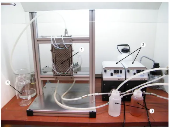
Figure 19. NETmix® reactor experimental apparatus. Legend: 1-NETmix® Reactor; 2-Feeding pumps; 3-Reactants vessels; 4-Final product flask.
Figure 20. Batch experimental apparatus. Legend: 1-Batch reaction vessel; 2-Peristaltic pump; 3-Reactants vessel.
The iron (III) cations were provided from a solution of iron (III) chloride hexahydrate (98% purity from Sigma-Aldrich), F eC l36 H O2 , and the source of fumarate anions is sodium
fumarate dibasic (99% purity from Sigma-Aldrich), N aO C -C H -C O N a2 2 2 2 . Sodium fumarate
was used instead of acid fumaric, because the latter has poor solubility in water. Therefore, there is no need of adding sodium hydroxide to increase the solubility of fumaric acid.
The chemical formula that represents the chemical reaction is:
2 μ3
+3 III - +
4 2 4 2 3 2 3 4 2 4 3 2
3Fe +3 C H O +5H O Fe O H O C H O nH O O H 3H (3.1)
Most of the experiments were performed at room temperature, but in order to study the effect of the temperature, a single experiment (in both reactors) was performed at 80 ºC. The reactants were heated up to 80 ºC, and the reactor temperature was set to the desired by passing hot water (in a closed circuit). Another experiment (batch) was performed to study the effect of the presence of a dispersant (see Table 2).
The following procedure was adopted. At the beginning and at the end (after 72 hours) of the ageing process, samples are collected and dried in a spray-dryer (Büchi Mini Spray Dryer B-290) to obtain a powder, that is used for SEM imaging, XRD, BET, DSC, TG, measurement of the particles size distribution, helium pycnometer method and mercury porosimetry. During the ageing process, approximately 30 mL of reaction solution was collected and centrifuged (Thermo Fisher Scientific Heraeus Multifuge X1R), for 30 minutes, at -5 ºC and a relative centrifugal force of 15000g. The solids were stored and the iron content in the supernatant was determined by atomic absorption spectroscopy.
In the performed experiments, the influence of 3 parameters in the final product was evaluated: Reynolds number in the NETmix® channels, reactants concentration and temperature.
In the first experiment N01, the Reynolds number and the reactants concentration were set to 600 and 0.4 M respectively. It was observed a strange phenomenon: blockage of some chambers of the reactor or no mixing (segregation of the flow) in the chambers. Either way, that was not the desired performance of the NETmix® reactor. To set the proper operational conditions of the NETmix®, in order to have good mixing in chambers, some rheological experiments were performed using a Paar Physica UDS 200 rheometer. The results of the rheological experiments are presented in section 3.2.1.
Table 2. Series of experiments.
Exp. Process R em in T (ºC ) Creac (M ) Objective
N01 NETmix® 78 25 0.4 Study the influence of the Reynolds number in the process.
N02 NETmix® 600 25 0.4
B02 Batch n.a. 25 0.4 Comparison of the batch production with NETmix® final product N02.
N03 NETmix® 600 25 0.02 Study the effect of lower
concentration.
N04 NETmix® 600 80 0.4 Study the effect of the temperature B04 Batch n.a. 80 0.4 Comparison of the batch production with NETmix® final product N04. B05 Batch n.a. 25 0.4 Study the effect of the addition of
sodium citrate as a dispersant
3.2 Characterization
The following techniques were used to characterize the final product. 3.2.1 Rheological experiments
In order to understand the behavior of the reaction mixture, while flowing, rheological experiments were performed. The main motivation for this study is the fact that, at a Reynolds number of 600 (in the channels), blockage of the reactor or segregation of the flow was observed which might indicate that the mixtures viscosity increased to a value that makes the actual Reynolds Number below the critical value. The objective is to try to predict the viscosity increase and adjust the operational conditions of the reactor, in order to keep a good mixing quality.
The experiments were performed in a cone-and-plate rheometer. The used cone has a diameter of 75 mm and the angle between the surface of the cone and the plate is 1º.
Rotational experiments were made, keeping the shear rate constant and measuring the torque over time (during 60 seconds). The temperature was set to 25 ºC and kept constant by using a Viscotherm VT2. A few milliliters of each reactant were placed in the rheometer’s plate. Both reactants were kept separated to avoid the contact between them (Figure 21) and to ensure that the reaction only occurs when the cone starts rotating and acquiring data. With these experiments, the relation between the solutions viscosity with time was obtained. This information is not only important to evaluate the increase of the viscosity, but can possibly give information about the crystallization kinetics.
Figure 21. Schematic of the rheological experiments procedure.
The viscosity over time was measured for the following reactants concentrations: 0.08, 0.16 and 0.4 M. For each concentration, 4 different shear rates were tested: 366, 713, 1426 and 2852 s-1, in a total of 12 different experiments. Each measurement was performed in triplicate to ensure reproducibility.
For every experiment, the same behavior was observed: in the first few seconds, the viscosity abruptly increases, reaching a maximum value, and then decreases, reaching a stationary value. The initial increase of the viscosity is expected due to the nucleation of particles that increase the flow resistance (see results in Appendix A).
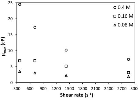
Figure 22 shows, for each concentration, the maximum viscosity (which determines the minimum Reynolds number) as a function of the shear rate.
As can be observed in Figure 22, when the reactants concentration is 0.4 M, the viscosity can increase to up 25 times the water’s viscosity (which was used to calculate the Reynolds number). It is observed that the maximum viscosity decreases with shear rate, for the same concentration. For a concentration of 0.4 M of iron chloride and sodium fumarate, the maximum viscosity decreases with shear rate according to equation 3.2, obtained by fitting the experimental data, using the method of least squares,
0 .6 0 7 m ax 8 9 4
(3.2)
Figure 22. Maximum viscosity of the reaction mixture as a function of the shear rate at 25 °C.
The shear rate in the channels of the NETmix® is given by (see Appendix C for more information)
6
d
(3.3)
where d is the channels depth (m).
This way, it is possible to determine the necessary flowrate for a given Reynolds number to be achieved.
3.2.2 Scanning Electron Microscopy (SEM) and Energy Dispersive Spectroscopy (EDS) Scanning electron microscopy is a widely used technique for obtaining particles images. It scans the sample with a beam of electrons that interacts with the surface of the sample, emitting different signals that contain information about the surface’s topography. Those signals are detected and converted to high-resolution images.
EDS is an analytical technique used for elemental characterization of a sample. The X-ray emitted by the sample due to the transitions of electrons from outer to inner layers is measured, and the energy spectrum can be related to the chemical element.
The used equipment for the analysis (owned by CEMUP - Centro de Materiais da Universidade do Porto) is a Jeol JSM 6301F microscope with Oxford Inca Energy 350 energy dispersive X-Ray system.
The samples were prepared by fixing the powder in a conductive carbon tape, which is fixed in a metallic holder. The samples needed to be coated with gold (for 220 seconds), due to its
0 5 10 15 20 25 300 600 900 1200 1500 1800 2100 2400 2700 3000
μ
m ax(cP)
Shear rate (s
-1)
0.4 M
0.16 M
0.08 M
low conductivity that leads to charge effect (accumulation of charges that lead to very bright images).
3.2.3 Dynamic Light Scattering (DLS)
Dynamic light scattering (also known as photon correlation spectroscopy) is a technique that measures the Brownian motion of the particles and relates with their sizes. The particles’ field is illuminated with a laser and the intensity fluctuations in the scattered light is analyzed. The particles size distribution is then correlated and determined from the acquired data.
The particles size distribution was measured using a Malvern ZetaSizer Nano ZS ZEN 3600. To measure the particles size distribution, the solids were diluted in ethanol, in a concentration of 1 mg/mL, kept under agitation of a magnetic stirrer for 3 minutes and then ultrasound waves were applied to the sample (for 3 minutes) at 30% of amplitude (using Hielscher UP50H ultrasound device). It was necessary to change the definitions of the ZetaSizer software, due to the solvent change. The following ethanol properties were used: R I 1 .3 6 0, r 24.3 and
1.04
cP [32, 33].
3.2.4 Electrophoresis (Laser Doppler Velocimetry)
Electrophoresis is the motion of dispersed particles under the influence of a uniform electric field. The dispersed particles have an electric surface charge, on which external field exerts a Coulomb force, and they are attracted towards the electrode of opposite charge. When the equilibrium is reached, the particles move with constant velocity (called electrophoretic mobility). The electrophoretic mobility is measured using the laser doppler velocimetry (LDV) technique, which uses the Doppler shift in a laser beam to measure the velocity of the particles. The electrophoretic mobility is then used to determine the zeta potential of the particles surface.
The zeta potential is the electric potential in the interfacial double layer at the location of the slipping plane versus a point in the bulk fluid, away from the interface (Figure 23).
The zeta potential is an important value that can be related to the stability of the dispersion. It indicates the degree of repulsion between adjacent, similarly charged particles in dispersion. High values of zeta potential (above 60 mV - absolute value) indicate that the dispersion is stable, and has no tendency to flocculate. Low zeta potential means that the attraction exceeds repulsion and the particles will flocculate, creating clusters.
The equipment used to determine the zeta potential distribution is the Malvern ZetaSizer Nano ZS ZEN 3600 using the folded capillary cell (DTS1060). The samples were prepared by
diluting the solution 25 times in water to ensure that the sample’s concentration is within the working range of concentrations of the device.
Figure 23. Electrical layers of the surface particles [34]. 3.2.5 Atomic Absorption spectroscopy
Atomic absorption spectroscopy is a method that measures the absorption of radiation and can be related to the concentration of a chemical species in a solution. This technique was used to determine the concentration of iron in the supernatant, thus making possible the determination of the chemical conversion of iron in MIL-88A.
The equipment used for atomic absorption is a GBC 932 Plus. The samples needed to be diluted in water in order to the iron concentration be within the detection limit range (2-145 mg/L).
3.2.6 X-Ray Diffraction (XRD)
X-Ray diffraction is an X-ray scattering technique used to identify unknown crystallized substances. The XRD spectrum gives information about the crystalline structure of the sample and allows the identification of the structure, by comparing the spectrum with spectrums of known substances.
These measurements were performed at Institut Lavoisier. The equipment used to obtain XRD spectra is a Bruker D8, equipped with an eye-Lynx detector (with a copper source).
3.2.7 Differential Scanning Calorimetry (DSC) and Thermogravimetric (TG) analysis Differential scanning calorimetry is a technique widely used in the field of thermal characterization of solids. It is a technique in which the sample is heated (with constant heating rate) and the difference in the amount of heat required to heat the sample and the
![Figure 3. Overview of synthesis methods, possible reaction temperatures and final products [7]](https://thumb-eu.123doks.com/thumbv2/123dok_br/15721907.1070567/19.892.230.686.275.640/figure-overview-synthesis-methods-possible-reaction-temperatures-products.webp)
![Figure 14. TEM images obtained from hydrothermal microwave synthesis of MIL-88A at various temperatures and synthesis times [18]](https://thumb-eu.123doks.com/thumbv2/123dok_br/15721907.1070567/30.892.221.695.695.1003/figure-obtained-hydrothermal-microwave-synthesis-various-temperatures-synthesis.webp)