PAPER REF: 6357
AXIAL BUCKLING RESISTANCE OF PARTIALLY ENCASED
COLUMNS
Abdelkadir Fellouh1, Nourredine Benlakehal1, Paulo A. G. Piloto2(*), A. B. Ramos Gavilán3, Luís M. R. Mesquita4
1
University Hassiba Benbouali (UHBC), Chlef, Algeria 2
LAETA INEGI, Department of Applied Mechanics, Polytechnic Institute of Bragança (IPB), Portugal 3
Department of Mechanical Engineering, University of Salamanca (USAL), Spain 4
ISISE, Department of Applied Mechanics, Polytechnic Institute of Bragança (IPB), Portugal (*)
Email: [email protected]
ABSTRACT
Partially Encased Columns (PEC) present good axial buckling resistance under fire, mainly due to the presence of concrete between flanges. The presence of concrete increases the mass and thermal inertia of the member and changes the variation of the temperature field within the cross section, in both the steel and concrete. The elastic buckling load of PEC under fire conditions may be calculated by the balanced summation method and by the finite element method. This work compares the results from both solution methods and provides the validation of the three dimensional model for different fire ratings of 30 and 60 minutes.
Partially encased columns, buckling load, fire resistance.
INTRODUCTION
Partially encased columns are usually made of hot rolled steel profiles, reinforced with concrete between the flanges. The composite section is responsible for increasing axial, torsional and bending stiffness when compared to the bare steel solution. The reinforced concrete is also responsible for increasing the fire resistance. In a composite column, both the steel and concrete are expected to resist the external loading by interacting together by bond and friction. Supplementary reinforcement in the concrete encasement prevents excessive spalling of concrete both under normal load and fire conditions. Due to the thermal and mechanical properties of concrete, composite columns always presents higher fire resistance than the corresponding steel bare columns.
Two methods are used to determine the elastic buckling resistance: the simple calculation method and the advanced calculation method. For convenience, the elastic buckling resistance is presented in non dimensional format, using the no dimensional slenderness at elevated temperature and ratio between the elastic buckling resistance and the plastic axial resistance, both for 30 and 60 minutes of ISO834 fire.
PARTIALLY ENCASED COLUMNS
end boundary conditions, using 3m column height. S275 and B500 grades were selected to steel while C20/25 grade was considered to concrete.
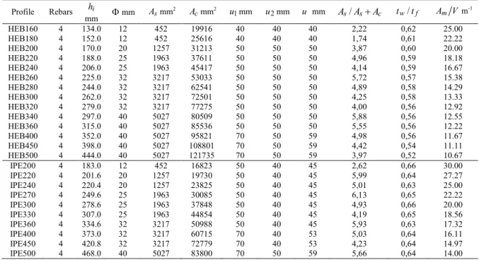
The cross sections were defined accordingly to the tabular design method for partially encased columns under fire (CEN, 2005). This leads to minimum dimensions and minimum distances between components. The design of this sections depends on the load level, and on the ratio between the thickness of the web and the thickness of the flange, see Fig. 1. This tabular method applies to structural steel grades S235, S275 and S355 and to a minimum value of reinforcement, between 1 and 6%. Table 1 presents the main dimensions, in particular the number of rebars, the diameter of each rebar, the cover dimensions in both principal directions
a) Cross section model b) Parameters for the simple cal. method
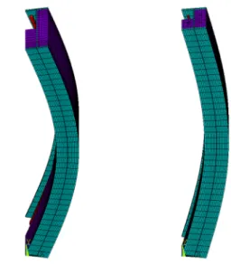
c) Buckling deformed shape mode and buckling length in fire d) Finite element approximation for HEB360 Fig. 1 Partially encased column under fire.
The fire resistance of partially encased columns may be calculated by the balanced summation method, which is based on the contribution of four components and depends on the temperature effect in each component. According to Eurocode 4, Part 1.2 (CEN, 2005), the fire resistance can be evaluated by this method, see annex G, considering the flanges of steel profile, the web of steel profile, the concrete and the reinforcement submitted to standard fire and for different fire resistance classes (R30 and R60). This method presents a few empirical coefficients that were rectified, but similar formulas are presented. These new results are much safer than the ones presented in Eurocode 4, Part 1.2 (CEN, 2005).
Table 1 Section properties for partially encased columns. Profile Rebars hi
mm Φmm Asmm 2
c
A mm2 1
u mm u2mm u mm As/As+Ac tw/tf Am V m1
HEB160 4 134.0 12 452 19916 40 40 40 2,22 0,62 25.00
HEB180 4 152.0 12 452 25616 40 40 40 1,74 0,61 22.22
HEB200 4 170.0 20 1257 31213 50 50 50 3,87 0,60 20.00 HEB220 4 188.0 25 1963 37611 50 50 50 4,96 0,59 18.18 HEB240 4 206.0 25 1963 45417 50 50 50 4,14 0,59 16.67 HEB260 4 225.0 32 3217 53033 50 50 50 5,72 0,57 15.38 HEB280 4 244.0 32 3217 62541 50 50 50 4,89 0,58 14.29 HEB300 4 262.0 32 3217 72501 50 50 50 4,25 0,58 13.33 HEB320 4 279.0 32 3217 77275 50 50 50 4,00 0,56 12.92 HEB340 4 297.0 40 5027 80509 50 50 50 5,88 0,56 12.55 HEB360 4 315.0 40 5027 85536 50 50 50 5,55 0,56 12.22 HEB400 4 352.0 40 5027 95821 70 50 59 4,98 0,56 11.67 HEB450 4 398.0 40 5027 108801 70 50 59 4,42 0,54 11.11 HEB500 4 444.0 40 5027 121735 70 50 59 3,97 0,52 10.67
IPE200 4 183.0 12 452 16823 50 40 45 2,62 0,66 30.00
IPE220 4 201.6 20 1257 19730 50 40 45 5,99 0,64 27.27 IPE240 4 220.4 20 1257 23825 50 40 45 5,01 0,63 25.00 IPE270 4 249.6 25 1963 30085 50 40 45 6,13 0,65 22.22 IPE300 4 278.6 25 1963 37848 50 40 45 4,93 0,66 20.00 IPE330 4 307.0 25 1963 44854 50 40 45 4,19 0,65 18.56 IPE360 4 334.6 32 3217 50988 50 40 45 5,93 0,63 17.32 IPE400 4 373.0 32 3217 60715 70 40 53 5,03 0,64 16.11 IPE450 4 420.8 32 3217 72779 70 40 53 4,23 0,64 14.97 IPE500 4 468.0 40 5027 83800 70 50 59 5,66 0,64 14.00
BALANCED SUMMATION METHOD
This method requires analytical formulas to take into consideration the effect of the fire (ISO, 1999) in four components, assuming the same methodology of EN1994 1 2 annex G (CEN, 2005). For the calculation of the critical load, the effective flexural stiffness needs to be determined. This quantity depends on the temperature effect on the elastic modulus and on the second order moment of area of four components, according to Eq. 1.
( )EI fi,eff,z=ϕf,θ( )EI fi,f,z+ϕw,θ( )EI fi,w,z+ϕc,θ( )EI fi,c,z+ϕs,θ( )EI fi,s,z (1)
In this equation ( )EI fi,eff,z represents the effective flexural stiffness of the composite section in
fire, ( )EI fi,f,z represents effective flexural stiffness of the flange, ( )EI fi,w,z represents effective
flexural stiffness of the web, ( )EI fi,c,z represents the effective flexural stiffness of the concrete
and ( )EI fi,s,z represents the effective flexural stiffness of reinforcement. The contribution of
each part is going to be weighted according to ϕ factors, see Table 2.
Table 2 Reduction coefficients for bending stiffness around the week axis. Standard fire resistance ϕf,θ ϕw,θ ϕc,θ ϕs,θ
R30 1,0 1,0 0,8 1,0
R60 0,9 1,0 0,8 0,9
R90 0,8 1,0 0,8 0,8
R120 1,0 1,0 0,8 1,0
The elastic buckling load Nfi,cr,z requires the calculation of the axial plastic resistance under
fire Nfi,pl,Rd. The non dimensional slenderness ratio λθ is also presented in Eqs. 2 4, when the
safety partial factors are assumed equal to 1.0. Lθ represents the buckling length of the
s Rd pl fi c Rd pl fi w Rd pl fi f Rd pl fi Rd pl
fi N N N N
N , , = , , , + , , , + , , , + , , , (2)
z cr fi Rd pl fi N
N , , , ,
=
θ
λ (3)
( )fieffz z
cr
fi L EI
N 2 2 , ,
,
, =π θ× (4)
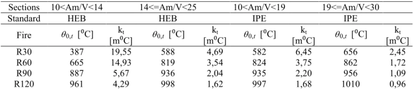
The effect of fire in the flange component requires a bilinear approximation for the calculation of the average temperature in flange, using a new empirical coefficient kt and a
new reference value θ0,t, see Eq. 5 and Table 3. The temperature is affecting the elastic
modulus of the material without any other reduction that could affect the second order moment of area.
(A V)
kt m t t f, =θ0, +
θ (5)
Table 3 Parameters to determine flange temperature (Section HEB and IPE). Sections 10<Am/V<14 14<=Am/V<25 10<Am/V<19 19<=Am/V<30
Standard HEB HEB IPE IPE
Fire θ0,t [⁰C] kt
[m⁰C] θ0,t [⁰C]
kt
[m⁰C] θ0,t [⁰C]
kt
[m⁰C] θ0,t [⁰C]
kt [m⁰C]
R30 387 19,55 588 4,69 582 6,45 656 2,45
R60 665 14,93 819 3,54 824 3,75 862 1,72
R90 887 5,67 936 2,04 935 2,20 956 1,09
R120 961 4,29 998 1,62 997 1,68 1010 0,96
The effect of fire on the web of the steel section was determined by the 400 °C isothermal criterion (Cajot et al, 2012) (R. Zaharia, 2011) (R. Zaharia, 2012). This procedure defines the affected zone of the web and predicts the web height reduction hw,fi, see Fig. 1. This new
formulae (Paulo Piloto et al, 2015) presents a strong dependence on the section factor, regardless of the fire resistance class (t in minutes), unlike the simplified method of EN1994 1 2 (CEN, 2005). The results of EN1994 1 2 are unsafe for all fire resistance classes and for all section factors. The new proposal presents a parametric expression that depends on section factor and standard fire resistance class, Eqs. 6 7. Both equations have the application limits defined in Table 4. This calculation is affecting the second order moment of area of the web, without considering any temperature effect on the reduction of the elastic modulus.
( ) 0.03 ( )/2 ,( )
0035 . 0 100 /
2 2 2.02
, h t A V t A V HEB
hwfi i× = × × m − × + m (6)
( ) 0.03 ( ) ,( )
002 . 0 100 /
2hw,fi hi× = ×t2× Am V − ×t1.933+ Am V IPE (7)
Table 4 Application limits for HEB and IPE cross sections regarding web component. Standard fire resistance Section factor (HEB) Section factor (IPE)
R30 Am/V <22.22 Am/V <30.00 R60 Am/V <15.38 Am/V <18.56 R90 Am/V <12.22 Am/V <14.97 R120 Am/V <11.11
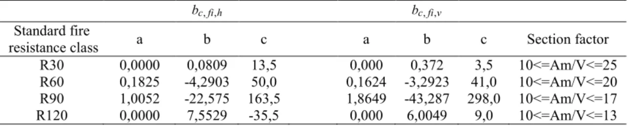
be neglected depends on section factor Am V, for standard fire resistance classes of R90 and R120. The new proposal (Paulo Piloto et al, 2015) demonstrates a strong dependence on the section factor for all standard fire resistance classes, see Eq. 8, and the applications conditions in Tables 5 6. The new proposal also differentiates the layer of concrete to be neglected in both principal directions. The average temperature of the residual concrete section may be calculated according to Eqs. 9 10. The new proposal introduces a parametric approximation, based on the standard fire resistance t and section factor Am V. The application limits are presented in Table 7. This calculation is affecting the second order moment of area of the concrete and also the elastic modulus of the material.
(A V) b (A V) c
a
bc,fi= × m 2+ × m + (8)
( ) 0.003 ,( )
1 .
3 0.5 1.95
,t t Am V t HEB
c =+ × × + ×
θ (9)
( ) 3.4 ,( )
67 .
2 0.5 0.61
,t t Am V t IPE
c =+ × × + ×
θ (10)
Table 5 Parameters and application limits for thickness reduction of the concrete in sections HEB.
h fi c
b, , bc,fi,v
Standard fire
resistance class a b c a b c Section factor
R30 0,0000 0,0809 13,5 0,000 0,372 3,5 10<=Am/V<=25 R60 0,1825 4,2903 50,0 0,1624 3,2923 41,0 10<=Am/V<=20 R90 1,0052 22,575 163,5 1,8649 43,287 298,0 10<=Am/V<=17 R120 0,0000 7,5529 35,5 0,000 6,0049 9,0 10<=Am/V<=13
Table 6 Parameters and application limits for thickness reduction of the concrete in sections IPE.
h fi c
b, , bc,fi,v
Standard fire
resistance class a b c a b c Section factor
R30 0,0000 0,2206 10,5 0,0000 0,9383 3,0 14<=Am/V<=30 R60 0,2984 8,8924 93,0 0,5888 15,116 135,0 14<=Am/V<=22 R90 1,3897 38,972 313,0 2,0403 50,693 393,0 14<=Am/V<=17 R120 0,0000 18,283 199,0 0,0000 48,59 537,0 14<=Am/V<=15
Table 7 Application limits for average temperature of the concrete. Standard fire
resistance class
Section factor (HEB)
Section factor (IPE)
R30 Am/V<25 Am/V<30
R60 Am/V<20 Am/V<23
R90 Am/V<17 Am/V<18
R120 Am/V<14 Am/V<15
( ) 7.5 0.1 8 390 ,( ) 1
.
0 1.1 1.765
,t t Am V t t u HEB
s = × × + × − × − × +
θ (11)
( ) 11.0 0.1 8 115 ,( )
0 .
14 1.795
,t Am V t t u IPE
s = × + × − × − × +
θ (12)
ADVANCED CALCULATION METHOD (FEM)
The nonlinear solution method was applied to calculate the temperature field. The finite element method requires the solution of Eq. 13 in the internal domain of the partially encased column and Eq. 14 in the external surface exposed to fire. In these equations: T represents the temperature of each material; ρ(T) defines the specific mass; Cp(T) defines the specific heat;
) (T
λ defines the thermal conductivity; αc specifies the convection coefficient; Tg represents
the gas temperature of the fire compartment, using standard fire curve ISO 834 (ISO, 1999) around the cross section (4 exposed sides); Φ specifies the view factor; εm represents the
emissivity of each material; εf specifies the emissivity of the fire; σ represents the Stefan
Boltzmann constant.
( )I ∂ ∂ ⋅ ⋅ = ∇ ⋅ ⋅
∇ (λ(T) T) ρ(T) Cp(T) T t (13)
( ⋅∇ )⋅ = ( − )+Φ⋅ ⋅ ⋅( 4− 4) (∂I)
)
(T T n αcTg T εmεf σ Tg T
λ (14)
The three dimensional model uses element SOLID70 and LINK33 to model the profile / concrete and rebars, respectively. SOLID70 has a 3 D thermal conduction capability, presenting eight nodes with a single degree of freedom (temperature at each node). The interpolating functions are linear and uses full integration points (2x2x2) to define the conductivity matrix. The finite element LINK33 is a uniaxial element with the ability to conduct heat between two nodes. The element has a single degree of freedom, temperature at each node. The interpolating functions are linear and this element uses exact integration to define the conductivity matrix. Fig. 2 represents the shape of each element. Perfect contact between rebars and concrete is assumed, being the nodes of both elements shared in space. The nonlinear transient thermal analysis was defined with an integration time step of 60 s, which can decrease to 1 s and increase up to 120 s. The criterion for convergence uses a tolerance value of the heat flow, smaller than 0.1% with a minimum reference value of 1x10⁶.
a) SOLID70, thermal analysis of steel.
b) LINK33, thermal analysis of rebars.
c) SOLID70, thermal analysis of concrete.
d) SOLID185, mechanical analysis of steel.
e) LINK180, mechanical analysis of rebars.
f) SOLID65, mechanical analysis of concrete.
Fig. 2 Finite elements used to build the three dimensional model of partially encased columns.
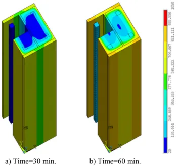
The temperature field was determined for the total time of 7200 s. Fig. 3 shows an example of the partially encased column exposed to ISO834 fire, after 30 and 60 minutes. The temperature field was recorded for the corresponding resistance class and applied as body load to the mechanical model. The mesh was defined after a solution convergence test.
a) Time=30 min. b) Time=60 min.
Fig. 3 Numerical results for column HEB 360 and for different fire ratings classes.
can be used to form the stress stiffness matrix
[
Kσ,ref]
. Since the stress stiffness matrix is proportional to the load vector{
Fref}
, an arbitrary stress stiffness matrix [Kσ] and an arbitraryload vector
{ }
F may be defined by a constant λ as shown by Eqs 16 17. The stiffness matrix is not changed by the applied load because the solution is linear. A relation between the stiffness matrices, the displacement and the critical load can then be presented as in Eq. 18, which can be used to predict the bifurcation point. The critical load is defined as {Fcri}. Sincethe buckling mode is defined as a change in displacement for the same load, Eqs. 18 19 are still valid, where { }δd represents the incremental buckling displacement vector. The difference between Eq. 18 and Eq. 19 produces an eigenvalue problem, represented by Eq. 20 where the smallest root defines the first buckling load, when bifurcation is expected.
[ ]K{ }d =
{
Fref}
(15)[Kσ]=λ
[
Kσ,ref]
(16){ }F =λ
{
Fref}
(17)[ ]
[
]
[
K +λcriKσ,ref]
{ }d =λcri{
Fref}
(18)[ ]
[
]
[
K +λcriKσ,ref]
{{ } { }d +δd}=λcri{
Fref}
(19)[ ]
[
]
[
K +λ Kσ,ref]
{ } { }δd = 0 (20)The trivial solution is not of interest, which means that the solution for λ is define for an algebraic equation, imposing the determinant of the global matrix equal to zero. The calculated eigenvalue is always related to an eigenvector { }δd called a buckling mode shape, see Fig. 4. This numerical solution of a linear buckling analysis assumes that everything is perfect and therefore the real buckling load will be lower than the calculated buckling load if the imperfections are taking into account.
RESULTS OF THE CRITICAL LOAD
The elastic buckling load is compared by two different solution methods. The simplified solution method applies to Eq. 4. The non dimensional slenderness ratio may be calculated using Eq. 3, when the safety partial factors are equal to 1.0.
The advanced solution method applies to the results of the buckling analysis, using the finite element method.
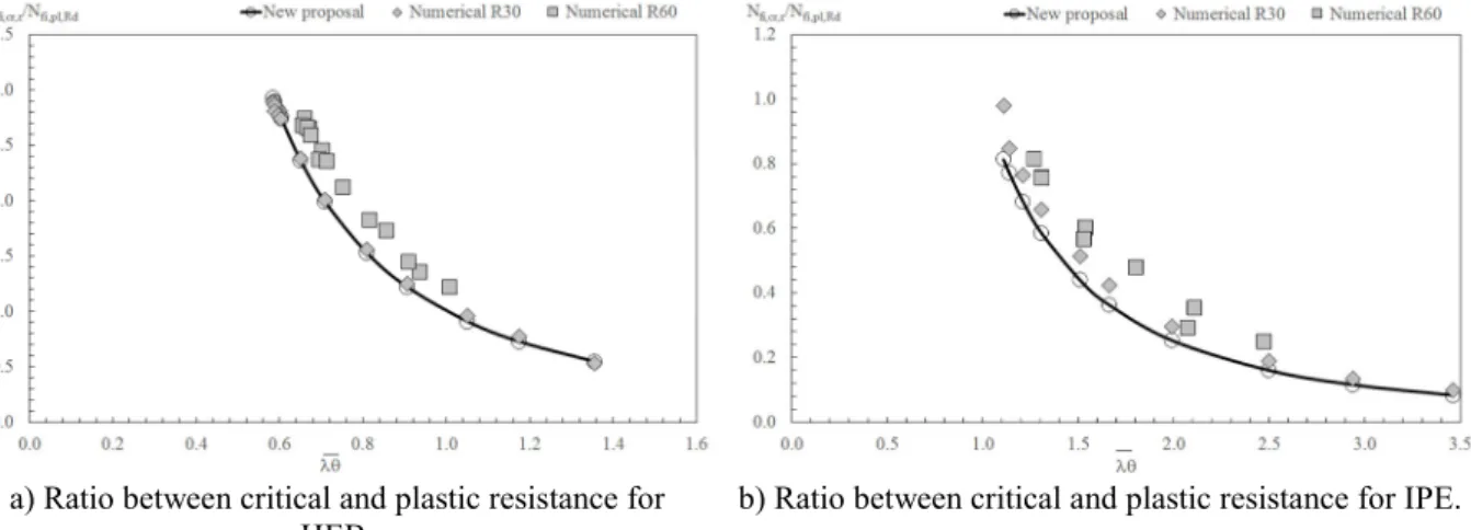
Fig. 5 presents the comparison of the buckling load results, using the new proposal and the numerical solution, for 30 and 60 minutes of fire exposure.
a) Ratio between critical and plastic resistance for HEB.
b) Ratio between critical and plastic resistance for IPE.
Fig. 5 Comparison of the critical load between the new proposal and the numerical results.
CONCLUSION
Two different solution methods were applied to define the elastic buckling load of partially encased columns in case of fire. The new proposal is based on the balanced summation method proposed by EN 1994 1 2, but using safer formulas for the components to account for a reduction in geometry and un update of the material properties based on its average temperature.
The numerical solution method is based on the elastic buckling analysis, considering the resistance of the four components, taking into account the update of the material properties and the full geometry of column. This fact justifies that the numerical results are always higher that the ones presented by the new formulae.
This work is ongoing to compare the prediction of the buckling resistance of partially encased columns and to validate the best fitting curve for axial buckling load.
REFERENCES
[1] CEN EN 1994 1 2; “Eurocode 4 Design of composite steel and concrete structures Part 1 2: General rules Structural fire design”; Brussels, August 2005.
pp: 29 38, Book of full papers ISBN 978 989 98435 5 4, ISSN 2412 2629, University of Coimbra, Portugal, 20th 22nd April 2015.
[3] ISO ISO 834 1. Fire resistance tests Elements of building construction – Part 1: general requirements. Switzerland, Technical Committee ISO/TC 92: 25, 1999.
[4] Cajot Louis Guy, Gallois Louis, Debruyckere Rik, Franssen Jean Marc, Simplified design method for slim floor beams exposed to fire, Proceedings of the Nordic Steel Construction Conference, Oslo, Norway, 5 7 September, 2012.
[5] R. Zaharia, D. Duma, O.Vassart, Th. Gernay, J.M. Franssen, simplified method for temperature distribution in slim floor beams, Application of Structural Fire Design, Prague, Czech Republic, 29 April 2011.