USE OF MEMBRANAS FOR BIOGAS PURIFICATION: REVIEW USO DE MEMBRANAS PARA PURIFICAÇÃO DE BIOGÁS: REVISÃO
Michelle Garcia Gomes1; Luís Carlos de Morais1; Daniel Pasquini1 Artigo recebido em: 16/05/2019 e aceito para publicação em: 17/06/2019.
DOI: http://dx.doi.org/10.14295/holos.v19i3.12339
Abstract: Biogas is a clean organic fuel that is produced by the decomposition of organic matter un-der anaerobic conditions, composed of about 55-65% methane, 30-45% carbon dioxide, traces of hydrogen sulphide and fractions of water vapour. The presence of compounds other than methane, although occurring at very low concentrations, is a problem since they are detrimental to any proces-sing equipment and restrict their use. Therefore, in order to achieve the standard biogas composition, it is important to include purification steps before using biogas. Traditional technologies for purification are essentially based on the use of physical and chemical methods, which also generate secondary pollutants, and are expensive. The current study is a review of different membrane-based biogas puri-fication processes that are widely used worldwide, and the key technologies being developed or under research. Appropriate membrane materials, as well as an efficient module and process design, deter-mine competitiveness with conventional separation technology.
Keywords:Purification. Biogas. Membrane. Methane.
Resumo: O biogás é um combustível orgânico limpo que é produzido pela decomposição da matéria orgânica sob condições anaeróbias, composto de cerca de 55-65% de metano, 30-45% de dióxido de carbono, traços de sulfeto de hidrogênio e frações de vapor de água. A presença de outros compos-tos além do metano, embora ocorram em concentrações muito baixas, é um problema, uma vez que são prejudiciais para qualquer equipamento de processamento e restringem seu uso. Portanto, para atingir a composição padrão de biogás, é importante incluir as etapas de purificação antes de usar o biogás. As tecnologias tradicionais de purificação baseiam-se essencialmente no uso de métodos físicos e químicos, que também geram poluentes secundários e são caros. O presente estudo é uma revisão de diferentes processos de purificação de biogás baseados em membranas que são ampla-mente utilizados em todo o mundo e as principais tecnologias sendo desenvolvidas ou em pesquisa. Materiais de membrana apropriados, bem como um módulo eficiente e projeto de processo, determi-nam a competitividade com a tecnologia de separação convencional.
Palavras-chave: Purificação. Biogás. Membrana. Metano.
1 INTRODUCTION
The high dependence of fossil fuels as a primary source for the generation of energy, determining the unsustainability of the energy matrix (MORERO et al., 2010,
the growing concern about the worsening climate phenomenon over the last dec-ades, and its direct relation to the emission of gases with greenhouse effect (GEE) (JARDIM, 2013), arising from the use of these fossil fuels, represents one of the great problems to the world.
Given that the process of recovering oil, coal and natural gas reserves is too slow, it is necessary to find alternatives quickly. The volatility and uncertainty in the oil market are also development motivations. Discharges of acid gases and the greenhouse gas effect are actually at levels that require immediate action to combat serious future problems. This is particularly true in the transport sector, one of the largest emitters of harmful gases such as carbon dioxide and methane in the world. Diversification and investment in other sustainably used sources of renewable energy such as wind, solar, thermal and biomass would contribute positively to an improve-ment in this scenario (MONTEIRO, 2011; IEA, 2007; PROBIOGÁS, 2016; PINHEIRO, 2015).
Wind and water technologies are mature and have shown considerable im-plementation in the current energy market. However, there are still other renewable sources to explore. Energy from biomass (MONTEIRO, 2011), such as biogas, wind power and solar power supply 14% of total world energy demand (KADAM, PANWAR, 2017).
Brazil presents several favourable aspects for the use of this type of energy source, such as its location, climate and territorial extension (SANTOS et al., 2014; SANTOS, LIMA, 2016). The most important biomass energy sources are wood, agri-cultural waste, solid waste, food processing waste, aquatic plants and seaweed. As a potential source of energy, biomass can be converted into electricity or into solid, liq-uid or gaseous fuels (SANTOS & LIMA, 2016; VASSILEV et al., 2010; VIERA et al., 2015).
The biogas market, the most sustainable of existing biofuels, is at the start of an exponential growth curve and taking advantage of this provides a chance to sub-stantially reduce emissions of both methane and CO2, particles, nitrogen oxide or
dust into the atmosphere and thus how to profit from carbon credits (JARDIM, 2013; MONTEIRO, 2011; IEA, 2007; GIA, 2010).
Biogas is one of the promising sources of energy and its use can be further optimised by applying gas separation technologies, thereby separating methane from carbon dioxide and other impurities. In this way, the resulting biogas (referred to as
biomethane) can be made compatible with natural gas in any of its common applica-tions, such as fuel for vehicles, the production of electricity and heat and as a raw material for the chemical industry (KADAM, PANWAR, 2017; SANTOS, LIMA, 2016; SCHOLZ, 2013; INOVAGRID, 2016).
Compared with other biofuels, treated biomethane is one of the most efficient options for low-impact climate mobility, especially due to the high surface efficiency (energy yield per hectare of cultivated area) and excellent combustion properties (PROBIOGÁS, 2016; SANTOS, LIMA, 2016).
About 75% of all biogas potential is concentrated in the anaerobic digestion of surplus crops, cellulosic biomass and agriculture and livestock residues, the remain-der being divided between landfills and sewage and sewage treatment plants (MONTEIRO, 2011; IEA, 2007; MARIN, 2011). Biogas consists mainly of methane (CH4) (55-70%), carbon dioxide (CO2) (30-45%) and hydrogen sulphide (H2S) (1-3%).
The concentration of different gases in biogas depends on the composition of the raw materials, the decomposition conditions, and the hydraulic retention time in the di-gester, among others (VIERA et al., 2015; VARNERO et al., 2012; CHEN et al., 2015).
Purified and methane-enriched biogas can be used for domestic applications, automotive fuel (liquefied), thermal energy (heat, dry, cool) or electricity generation (KADAM, PANWAR, 2017; HARASIMOWICZ et al., 2007; KAPDI et al., 2005). To-day, it is possible to produce biogas in Brazil using state-of-the-art German technolo-gy from enertechnolo-gy plants and animal and agro-industrial waste (COELHO et al., 2014; COELHO et al., 2015).
The technical and economic viability for biogas energy utilisation starts with a study to determine the amount of biogas that will be produced and the amount that will be available for the generation of energy (PINHEIRO, 2015). In Europe, the tar-get market for biomethane from agriculture is Germany, where the first plants were started in 2007. Other countries, such as Austria, Switzerland, Sweden and the Netherlands, have developed the industry with the establishment of numerous plants (MOLINO et al., 2013; TENCA et al., 2011; PETTERSON, WELLINGER, 2009).
It is worth mentioning that the choice of technologies for the treatment and use of biogas depends on the composition, quantity, continuity of biogas production and local conditions of the plant rather than the type of substrate used (INOVAGRID,
For the use of biogas, it is imperative to find technological solutions that fit into the different biogas production scales, and select technologies and design systems to treat it to the level required by the type of use. There is a great need to make bio-gas transportable. This can be done by compressing the bio-gas into cylinders, which is only possible after the removal of CO2, H2S and water vapour. Thus, the major
ob-stacle to the development of the biogas market is the high cost of biogas purification and cleaning technologies (MONTEIRO, 2011; INOVAGRID, 2016; HARASIMOWICZ et al., 2007; SMYTH et al., 2010).
Many companies in numerous areas are starting to offer solutions to meet the demand for biogas purification solutions (MONTEIRO, 2011). Recently, the first bio-gas modernisation facilities were installed in Europe and the USA using technologies from the chemical process industry and natural gas treatment to remove CO2 from
CH4 (SCHOLZ et al., 2013).
The technical development of most biogas purification methods nowadays is generally sufficient to meet the needs of a potential system operator if CH4 is used as
a transport fuel. It only has to find a source of the most economic process for the production of biogas (MOLINO et al., 2013).
Membrane technology is analogous to conventional gas separation processes [13]. Currently, the polymer membranes show a good level of competitiveness with conventional technologies for the separation of CO2 and H2S from biogas, both with
respect to performance and the simplicity of the process (MOLINO et al., 2013). The objective of this review work is to discuss the main biogas purification technologies using membranes, which are widely used all over the world.
2 BIOGAS
Biomethane is a gas product from a renewable energy source, such as biogas, followed by the improvement process associated with a purification treatment (MOLINO et al., 2013). It is a colourless, highly combustible gas, due to the presence of the methane component, and has a calorific value that can vary between 35 and 77 kcal/m³ (PINHEIRO, 2015; CHEN et al., 2015; ARAGONESE et al., 2006; SANTOS, SANTOS, 2005).
Biogas can be used for various uses of energy, depending on the source of biogas used for production. It can be directly used to produce heat by direct
combus-tion (thermal utilisacombus-tion), the produccombus-tion of electricity by fuel cells or microturbines, combined heat and electricity (CHP) (electric and thermal energy) or as fuel for vehi-cles. However, the low calorific value of biogas is one of the main bottlenecks in the conversion of biogas to chemical or thermal energy (MONTEIRO, 2011; KADAM, PANWAR, 2017; SCHOLZ et al., 2013; MARIN, 2011; SEADI et al.,2008; HOSSEINI, WAHID, 2013; STERNAD, 2010). These activities are governed by national laws, as each country has a differentiated system of taxes and subsidies. In Europe, for ex-ample, it is more common to use biogas for vehicular use and gas grid injection (PINHEIRO, 2015; KADAM, PANWAR, 2017; THRÄNET et al., 2014).
There are other possibilities for the monetisation of this product, such as injec-tion into the natural gas network and compression and storage in tanks for later use in vehicles or at home. Obviously, these applications imply that the biogas is cleaned and purified to increase its calorific power. New ways to take advantage of biogas are still being investigated, highlighting the possibility of this biofuel with regard to playing an active role in the formation of the so-called synthesis gas; this is very important in several chemical industries (MONTEIRO, 2011).
The global biogas market has been growing over the past few years, and sev-eral countries are continuing to develop new production technologies and foster the competitiveness of national markets for their use, primarily through government in-centives. Ten EU countries (Germany, Denmark, Estonia, Finland, France, Italy, Po-land, the Netherlands, Romania and Spain) have already defined regulations to allow injection into their gas network (JARDIM, 2013; SNV WORLD, 2012).
The four largest biogas producers worldwide are Germany, Sweden, India and China. Germany, with some 7,000 producing units, accounts for more than half of the total primary energy produced from biogas. This is largely explained by the large state incentive for plantations for the production of biomass energy. Biogas already supplies more than 3% of the total electricity consumption, as well as representing significant amounts of thermal energy to industries, fuel for vehicles and volume in-jected into the natural gas network (JARDIM, 2013; KADAM, PANWAR, 2017; IEA, 2012; WBA, 2013).
Sweden is currently the world leader in the production of biomethane for use in vehicles. This fuel has already been used in several public transport and private transport fleets (trains and buses are operated on biogas with street refuelling
sta-1800 buses, 600 trucks, and the remaining light vehicles being largely owned by the municipalities. The number of biogas upgrade units at the end of 2011 was 47, rep-resenting a growth of 22% since 2008. This country plans to be the first oil-free economy by 2020. The main source of biogas in Sweden is sludge from wastewater treatment plants, followed by landfills. In 2003, in order to foster the growth of renew-able production, the Government instituted a system called the Green Gas Certifi-cate. Producers receive a certificate for each MWh of renewable energy which they can sell to users so that they meet the quota to which they are obliged by law. The Government also guarantees a 30% investment subsidy for the construction of bio-gas plants and introduced a series of measures to encourage the consumption of biofuels in transport, being one of the few countries in the world to have already regu-lated the characteristics of biomethane to vehicles through the 1999 document “Swe-dish Standard 155438 – Motor Fuels – Biogas as fuel for high-speed otto engines” (JARDIM, 2013; KADAM, PANWAR, 2017; WBA, 2013).
China and India, two other large producers, built (between April 2010 and March 2011) some 2.8 million and 150,000 new biogas plants. In these countries, very simple technologies have been used, which allow greater ease of reproduction and implementation (JARDIM, 2013; SNV WORLD, 2012). In India, the Ministry of New and Renewable energy had set a target to reach 48.55 MW of energy from bio-gas facilities by 2022. There is huge potential in India as well as the rest of the world to employ anaerobic digestion as a method of waste treatment, as well as an energy production technology (KADAM, PANWAR, 2017; MNRE, 2015).
In addition to these, the Netherlands had, by the end of 2011, 130 biogas plants and 13 biomethane producers. All 13 units inject the biomethane into the natu-ral gas network. During the last decades, Dutch companies have made an important contribution to upgrading the technologies and today are the most important players in the market. In its National Action Plan for Energy (PNAER), the 2020 target for bi-omethane production is 6.7 TWh (JARDIM, 2013).
Biogas produced by the anaerobic digestion of organic matter in sanitary land-fill, renewable organic resources (can be found in places where cellulose is decom-posed) and biodigestors mainly consists of two gases: methane (CH4) (estimated at
60%) and carbon monoxide (CO2) (35%); together, these account for more than 95%
of the biogas composition. In addition to these elements, others are also found in smaller quantities: H2, hydrogen, NH3, H2S (a fixed maximum rate of 1%), O2
(oxy-gen), CO (carbon monoxide), N (nitrogen) and H2O (water) (4%). However, several
studies have shown that biogas may contain 577 trace compounds, including halo-genated hydrocarbons, higher alkanes (greater than C2), and aromatic hydrocar-bons. Usually, traces of compounds constitute only 1% of the biogas volume. The use of substrates, the fermentation technology applied, and the collection method can affect its composition, i.e. the biogas composition depends largely on the type of residue digested and the specific characteristics of the digester. Thus, the physical characteristics of biogas consequently vary with chemical composition. The energy potential of the biogas is established as a function of the amount of CH4 contained in
the gas, which determines its calorific power (MORERO et al., 2010; MONTEIRO, 2011; MARIN, 2011; MOLINO et al., 2013; STERNAD, 2010; DEUBLEIN, 2010; FRONDIZI, 2009; ABATZOGLU, BOIVIN, 2009; ABBM, 2016; CHMIELEWSKI et al., 2013; ROSSI, 2014). Landfill gas, for example, has a somewhat different composi-tion, characterised by high pollutant load, especially percentages of silicon and hy-drogen sulphide. For this reason, landfill biogas cleaning is more expensive and cost-ly (PROBIOGÁS, 2016).
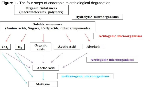
In detail, biogas is generated in a biochemical conversion, i.e. anaerobic di-gestion or fermentation of suitable substrates. The process of anaerobic didi-gestion, or simply biodigestion, is a complex metabolic process with the participation of different microorganisms and is the method used in the vast majority of existing biogas pro-duction processes. The processing chain always occurs in four interdependent stag-es (Figure 1): hydrolysis, acidogenstag-esis, acetanogenstag-esis and methanogenstag-esis, which is the methane formation phase (JARDIM, 2013; PROBIOGÁS, 2016; KADAM, PANWAR, 2017; STERNAD, 2010; MOLINO et al., 2013a; BROWN et al., 2012).
Figure 1 - The four steps of anaerobic microbiological degradation
It is necessary to observe some properties such as humidity, pressure, acidity, contaminants, the presence of non-combustible (CO2) and corrosive (H2S)
substanc-es, the quality and selection of the biogas conversion technology produced, as well as the calorific value and composition of the biogas, particle size, waste disposal time and air impermeability (SANTOS, LIMA, 2016; INOVAGRID, 2016; MARIN, 2011). The special advantage is the CO2 neutral balance; the combustion of biogas does not
produce new greenhouse gas effects, in addition to helping to increase its calorific power (HARASIMOWICZ et al., 2007; STERNAD, 2010).
On the other hand, some aromatic compounds (e.g. benzene) and chlorinated hydrocarbons (e.g. chloroethene) can cause health damage, others are very odorif-erous (e.g. terpenes, esters and thiols) and some may damage the gas utilisation plant (e.g. organohalogen and sulphur-H2S species are the most damaging, and are
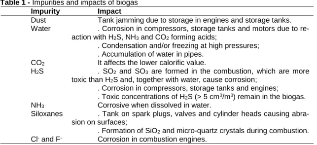
found along with sulphur compounds and siloxanes). Therefore, biogas purification is important both from the point of view of health and the environment, as it impacts on the functioning and efficiency of biogas equipment and must be performed to prevent problems with the subsequent use of biogas. The advantage of this type of fuel is that it is environmentally friendly, clean and inexpensive (MORERO et al., 2010; KADAM, PANWAR, 2017; VIERA et al., 2015; VARNERO et al., 2012; MOLINO et al., 2013a; VÍQUEZ, 2010; GISLON et al., 2015). Table 1 shows the main impurities, which, if not removed and/or treated, can have several consequences (JARDIM, 2013; SANTOS, LIMA, 2016; MOLINO et al., 2013; TILAHUN et al., 2017).
Table 1 - Impurities and impacts of biogas Impurity Impact
Dust Tank jamming due to storage in engines and storage tanks. Water . Corrosion in compressors, storage tanks and motors due to
re-action with H2S, NH3 and CO2 forming acids;
. Condensation and/or freezing at high pressures; . Accumulation of water in pipes.
CO2 It affects the lower calorific value.
H2S . SO2 and SO3 are formed in the combustion, which are more toxic than H2S and, together with water, cause corrosion;
. Corrosion in compressors, storage tanks and engines;
. Toxic concentrations of H2S (> 5 cm3/m3) remain in the biogas. NH3 Corrosive when dissolved in water.
Siloxanes . Tank on spark plugs, valves and cylinder heads causing abra-sion on surfaces;
. Formation of SiO2 and micro-quartz crystals during combustion. Cl- and F- Corrosion in combustion engines.
Biogas cleaning (removal of condensates, H2S, ammonia, siloxanes and
wa-ter) and biogas purification (removal of CO2 (and possibly N2) to improve the calorific
value) bring it to levels close to that of natural gas (MONTEIRO, 2011; VIERA et al., 2015; HARASIMOWICZ et al., 2007; BENITO, 2004).
The main measures are the separation of carbon dioxide and hydrogen sul-phide from biogas, as well as drying to reach a methane content of more than 95%, i.e. biomethane as a substitute for natural gas. For the different stages of the treat-ment of biogas, there are different processes available; obviously, these take into account economic and procedural factors. First, physical procedures are applied, based on adsorption (PSA system) and absorption (water washing), refrigeration and filtration (membrane separation and cryogenic process), as well as chemical absorp-tion processes (amine washing) (PINHEIRO, 2015; KADAM, PANWAR, 2017; SCHOLZ et al., 2013; MARIN, 2011; ABBM, 2016; SANTOS, 2014; HAIDER et al., 2016).
The criteria for choosing the most appropriate technology are: the need for pre-purification, control level, loss of methane, quality of methane produced (% CH4),
pressure used, need for electricity, need for heat and use of chemicals (PINHEIRO, 2015; ABBM, 2016). Most of these technologies are still imported and the selection of one or another method depends on the cost-benefit analysis of the proposal used. Generally, the fundamental disadvantages are that they are processes with high op-erational and investment costs; however, studies to improve the efficiency of these are continuing (VIERA et al., 2015; ABBM, 2016).
As mentioned, for this biogas, cleaning technology is available which is techni-cally and economitechni-cally feasible. The main one is the use of gas separating mem-branes. This method is attractive because it is cheaper and does not require large equipment, consequently using a compact plant, and because it does not produce separation effluents (PINHEIRO, 2015; MAKARUK et al., 2010).
However, the future of biogas is mainly focused on feedstock, and guidelines to purify biogas to pipeline quality. The future of biogas will depend on how markets of renewable energy will be developed (KADAM, PANWAR, 2017).
3 MEMBRANES
The great interest in the separation of generated gases started in the 1970s, with the development of research into synthetic elements that imitate the classic pro-cesses of separation; among these were membranes. This synthetic selective barrier has unique selection properties. Basically, the membrane is an interface that sepa-rates components from a given fluid. This separation occurs due to the affinity of some elements to the membrane, either by chemical or physical properties (JARDIM, 2013; PINHEIRO, 2015; BASSETTI, 2002). The success of this and other membrane separation systems led to intense research and innovation throughout the 1980s and 1990s, particularly with regard to the materials used. These are nowadays applied in a wide range of industrial processes (JARDIM, 2013; BASSETTI, 2002; SICILIANO, 2017; SCHOLES et al., 2008).
While biogas purification, to make methane useful for power generation, is an emerging technology, its application in energy and heat generation is not new. In the US and the European Union, there are several plants that use gas separation mech-anisms to reform biogas, totalling 402 plants. The latest developments indicate that membrane technology will reach a larger market share in the coming years. The ex-isting market is shared between different technologies (PINHEIRO, 2015).
The separation process with this synthetic selective barrier can be described as the component of greater affinity which will permeate the membrane, giving rise to definitions like permeating and non-permeating; this means that the component has a lower affinity for the membrane, which is called retained or retentate. Both the per-meate and retentate may be the stream containing the desirable components, be-cause the objective is to separate the elements (PINHEIRO, 2015; SOARES, 2012).
The potential for the application of membranes in the separation of gases is highlighted in the international market and depends on a number of factors. The first is certainly associated with energy and the supply available for its costs. Second is the environmental and social factor, with various types of regulation to be followed. The third and final factor is the technical feasibility of applying these mechanisms (PINHEIRO, 2015).
According to Jardim (2013) and Haider et al. (2016), there are two characteris-tics that dictate membrane performance: permeability (the flow of a specific gas across the membrane) and selectivity (the preference of the membrane to let one gas pass and prevent other).
Membrane systems, in turn, can compete with other carbon dioxide recovery processes. In the permeation of gases using membranes, the main advantage in comparison to other mechanisms is the low capital investment and low cost of pro-cessing (delivery, installation, pre-treatment, energy and maintenance) (PINHEIRO, 2015; SICILIANO, 2017; SOARES, 2012).
The ease of operation of the mechanism, reducing the area occupied, is also allied in the choice of this process, especially for places with restricted weight. In ad-dition, membranes have a low environmental impact and are very reliable (PINHEIRO, 2015; SOARES, 2012).
However, for example, the feed stream of the membrane must be pre-treated due to contaminants contained in the landfill gas, mainly those containing sulphur in their composition. The particulates and elements in the liquid state cannot come into contact with the membrane, to prevent damaging it. In addition, since the membrane uses a motive force due to the pressure difference, there may be a requirement for the gas to be compressed before entering the plant (PINHEIRO, 2015; SICILIANO, 2017).
On the other hand, according to Pinheiro (2015), the main competitor of mem-branes is the conventional diethylamine (DEA) process, which is also used to sepa-rate acid gases from natural gas. Of course, it is not a general rule, but a guide, as some studies mention when and which operating processes are the most appropriate depending on CO2 concentration. For concentrations less than 2%, there are no
cost-effective procedures, since this is usually the concentration pattern that is aimed for. As urban waste gases can produce a methane-rich gas containing up to 40% carbon
dioxide with various impurities to be treated, the application of the membrane pro-cess is more appropriate.
There is also the option of combining these two processes that have already been studied in the literature and are employed for high concentrations and high gas flows (generally for offshore oil plants). Initially, combining membranes with amine units to remove large amounts of CO2 from natural gas offers a low-cost alternative.
The membrane unit removes approximately 65% of the available carbon and the amine plant removes the remainder (PINHEIRO, 2015; BRACCIO et al., 2011; BAKER, LOKHANDWALA, 2008).
The choice of membrane is not made by separation processes, but is based on the chemical parameters. A membrane can be used in a number of different pro-cesses, for example, cellulose acetate; although it has been developed for use in wa-ter desalination, it is also used in the permeation of gas to separate carbon dioxide from natural gas (PINHEIRO, 2015).
The selection of the correct material is one of the major challenges for the in-dustry in the production of synthetic membranes due to the definition of the parame-ters seen in the transport mechanism. Considering the process economics, the membrane choice is based on the flow rate and the selectivity for the worked gas mixture. From this, the membrane operating conditions are evaluated, such as me-chanical strength, durability and separation efficiency (PINHEIRO, 2015).
There are three types of modules for gas permeation: hollow fibre modules, spiral wound modules and envelope-type modules (SCHOLZ et al., 2013; SCHOLZ et al., 2011).
For Chmielewski et al. (2013), the efficiency of the gas separation process can be described by two parameters: the product gas purity and the gas fraction in the feed recovered with the product (the recovery). These parameters are determined by the intrinsic properties of the membrane, such as permeability and selectivity, as well as operational factors such as total and partial pressure on the feed and permeation sides, feed rate and pressure drop on each side of the membrane. These factors de-termine the area of the membrane and the compression work that is necessary for an economic evaluation of the separation process.
Synthetic industrial membranes are based on two classes of materials to fa-vour the high transport rate of elements: organic materials, mostly polymers, and in-organic materials such as metals, glass and ceramics. Essentially, in-organic
com-pounds have a shorter shelf life compared to inorganic ones, and require a more complex cleaning process. On the other hand, those of an organic nature have a lower manufacturing cost (PINHEIRO, 2015; SCHOLZ et al., 2013; BAKER 2001). The inorganic or metallic membranes are prepared with structures that look like disks and, posteriorly, are stacked in a vase. Although vulnerable to breakage because they are very thin, they are highly temperature resistant. Another type of membrane configuration is the spiral, which is used in liquid separations. This consists of alter-nating layers of membrane and spacing, to promote feed and permeation channels, and turbulence. The third mode that is most often used for the permeation of gases, especially biogas, is that of hollow fibres. They are longitudinal membranes, with a high density of packaging and which do not allow the concentration of polarisation of the species. Finally, the last configuration to be used is that of a membrane contac-tor, which is a unit that uses the membrane as a barrier between a gas and a liquid. The component to be removed is dissolved in the membrane, directed to the liquid phase (PINHEIRO, 2015; PABBY et al., 2009; BELAISSAOUI et al., 2016).
Membrane contactors do not provide selectivity but act as barriers to separate two phases and increase the interfacial contact area for mass transfer. Wetting is the most critical challenge in membrane contactors with chemical absorbents. Thus, ab-sorbent selection is of great significance in membrane contactors for biogas upgrad-ing. However, there have been few studies of membrane contactors with renewable absorbents for biogas upgrading (HE et al., 2018).
Basically, most polymers can be used as a barrier. The state of the polymer is very important to characterise the properties of the membrane and to base the choice of the separation process upon. The properties in question are the molecular struc-ture, durability, crystallinity, degradation and levels of performance over time (PINHEIRO, 2015; PABBY et al., 2009).
According to Pinheiro (2015), the indication of hollow fibres for gas permeation is also valid due to the common problems that other membranes present and, espe-cially for this type of membrane and application, are not worrisome. The design cost for these membranes by area are the lowest in the market, in addition to having scale resistance, as gas streams are easily filtered, and the polymers constituting these membranes are glassy polymers that easily form this module. Confirming this, Hara-simowicz et al. (2007) stated that the occurrence of incrustations makes a
non-separation (GS) modules can have high packing density, e.g. high area-to-volume ratio (m2/m3). The most appropriate are hollow fibres, since they have high
mechani-cal strength, which is important when high pressure gas is applied inside or outside the membrane capillary. In the case when raw gas pressure is higher than 2MPa, the gas is fed from outside since the hollow fibres are more resistant to compression than to stretching. In the case when gas pressure is low, the feed is introduced inside the micro-pipe. Currently, manufactured hollow fibres are composed of nonporous separation layers (placed on the outer or inner side of the fibre or capillary) and po-rous support.
The membrane is characterised by its chemical and physical properties. Es-sentially, its interface can be classified according to its structure, composition, and load, among other subdivisions. The diffusion properties define the morphology of the membrane (dense or porous) and the selective capacity of the membrane so that the type of gas separation process to be performed is chosen (PINHEIRO, 2015; ROSSI, 2014; BASSETTI, 2002).
The porous interface is characterised by diffusion through the transfer of mat-ter by flow into the pores, and the dense synthetic inmat-terface, in turn, is characmat-terised by the transport of the elements by diffusion into the membrane material itself (PINHEIRO, 2015; ROSSI, 2014).
Besides the specific physical morphology (with pores or not), the membrane is also classified as morphology along its thickness. If the membrane is homogeneous, totally porous or totally dense, it is called this group of isotropes. If the membrane presents an asymmetric structure characterised by a thin layer (dense or porous) supported in a region with pores; this group is called anisotropic. This thin layer may be of the same material as its carrier, an integral membrane, or may be of a different material, a composite membrane (PINHEIRO, 2015; ROSSI, 2014).
When the pore size is small compared to the mean-free-path of the gas mole-cules, gases with lower molecular weights permeate much faster. The selectivity of porous materials is proportional to the square root of the molecular weights ratio; therefore, the enrichments that can be achieved with this method are small. The low efficiency of using a single module requires many separation stages. The membrane technique became more popular when the method of dense membrane manufactur-ing was developed. Gas transport through dense polymeric membranes is based on a solution-diffusion mechanism, which occurs in three steps. First, on the high
pres-sure side (in the upstream), the gas molecules dissolve on the membrane face. Next, the penetrating molecules diffuse across the membrane until they are desorbed at the downstream face of the membrane (CHMIELEWSKI et al., 2013).
The selective capacity in the processes of dialysis, microfiltration, ultrafiltration and nanofiltration is directly related to the size of the components in the fluid and the porosity of the membrane. In these cases, the fluid is theoretically inert to the mem-brane structure, prioritising diffusion by the flow of elements through the pores only (PINHEIRO, 2015).
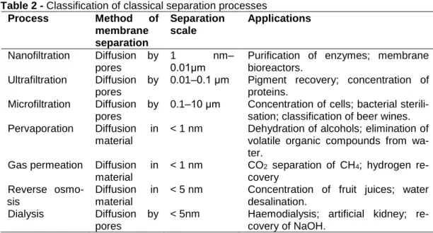
In parallel, the selective capacity in gas permeation and pervaporation pro-cesses are directly related to the nature of the membrane material. Since the mem-brane has no pores in its structure, the dominant driving force in these separation processes is diffusion through the membrane material itself, which occurs due to the affinity of the components in the fluid with the membrane material (PINHEIRO, 2015). A schematic of the separation processes with their application characteristics are de-scribed in Table 2.
Table 2 - Classification of classical separation processes Process Method of membrane separation Separation scale Applications Nanofiltration Diffusion by pores 1 nm– 0.01μm
Purification of enzymes; membrane bioreactors.
Ultrafiltration Diffusion by pores
0.01–0.1 μm Pigment recovery; concentration of proteins.
Microfiltration Diffusion by pores
0.1–10 μm Concentration of cells; bacterial sterili-sation; classification of beer wines. Pervaporation Diffusion in
material
< 1 nm Dehydration of alcohols; elimination of volatile organic compounds from wa-ter.
Gas permeation Diffusion in material
< 1 nm CO2 separation of CH4; hydrogen re-covery
Reverse osmo-sis
Diffusion in material
< 5 nm Concentration of fruit juices; water desalination.
Dialysis Diffusion by pores
< 5nm Haemodialysis; artificial kidney; re-covery of NaOH.
The permeability of a polymer for gases is dependent on the membrane state, the nature of the gas and the interactions between them. Glassy polymers are most often used in CO2/CH4 separation because of their high permeability and outstanding
thermal/chemical stability (CHMIELEWSKI et al., 2013).
While permeating through the membrane, the gases are separated due to the differences in diffusivity and solubility in the membrane matrix. The diffusion process
in glassy polymers is more complex compared to that in rubbery ones and depends on the diameter of the gas molecule. Gas diffusion in the polymer matrix proceeds only in free volume, which generally occurs in glassy polymers (CHMIELEWSKI et al., 2013; TILAHUN et al., 2017).
The permeability of the membrane is inversely proportional to the membrane area required for the separation, in other words, determined by its solubility and its diffusivity in the membrane. In this way, the solubility increases with the increase in affinity between the polymer and the molecule. Diffusivity, in turn, depends on both the size of the molecule and the choice of polymer. It can be measured by its diffusiv-ity coefficient, which shows that the smaller the molecule size, the greater the diffu-sion coefficient. Thus, an evaluation between the ratios of the main biogas molecules can be made as a function of their separation. Of all the types of membrane modules, the hollow fibre has the most extensive contact surface. To maximise the area, very small tubes are packed close together (CHMIELEWSKI et al., 2013; PINHEIRO, 2015).
Permeation, also known as “imbuing”, is the penetration of permeate such as liquid gas or vapours through a solid. It is directly related to the concentration gradi-ent of the permeate, i.e. a materials intrinsic permeability and mass diffusivity (KADAM, PANWAR, 2017).
In addition to the nature of the membrane material that affects its permeability, there is also another concern in improving these parameters by considering how the feed flow can be directed to the barrier. This new challenge began to be considered due to the appearance of problems like the polarisation of the concentration, the pressure drop of the fluids and the transfer of heat during the mechanisms of separa-tion. Thus, the membranes are configured in modules (PINHEIRO, 2015; PABBY et al., 2009).
There is a difference in the sorption process of molecules by the polymer de-pending on its solid, rubbery or vitreous state, especially when counting dense non-porous membranes. By progressively raising the temperature of the polymer, there is a transition band containing the so-called glass transition temperature (Tg), from
which the glassy polymer reacquires its mobile, rubber state. Upon reaching this state, the free volume in the polymer increases; that is, the volume unoccupied by the macromolecule gives space to other molecules to permeate in its structure (PINHEIRO, 2015; SOARES, 2012; OLAJIRE, 2010).
Pinheiro (2015) also mentions that, in glassy polymers, the segmental move-ments of the chains are more restricted and these materials are therefore able to more effectively discriminate the small differences in molecular dimensions. They exhibit higher selective mobility compared to rubber polymers due to the fixed free volume for diffusion. Thus, in the permeation of gases, there is a need to work with vitreous polymers with high Tg so that this change of state does not occur during the
separation process. The permeability of the rubber membrane is higher than the permeability of the vitreous membrane.
It has been reported in the literature, since 1999, that ceramic utility mem-branes have their own characteristics. In the separation of gas mixtures, dense, na-noporous or subnanometric membranes are useful and have been used in the
sepa-ration of mixtures of carbon/methane, and
diazotodihydrogenphos-phate/ammonia/nitrogen dioxide, among others. It is believed that there may be some catalytic activity of the membrane in some cases, allowing a considerable en-richment of 1:1:1 methane/ethane/propane mixtures increasing to 64% of the mass of methane and decreasing or almost eliminating the content of propane in a single step (VIERA et al., 2015).
In short, the natural gas processing industries are developing and expanding their applications. The use of large-scale membranes in the productions is focused primarily on the use of glassy polymers because of the selectivity that they provide for carbon dioxide. The majority of membrane producers today use cellulose acetate, which has greater solubility for carbon dioxide, and polyimides, which have a higher coefficient of diffusivity, with the hollow fibre module or spiral (PINHEIRO, 2015; CHEN et al., 2015; PETTERSON, WELLINGER, 2009; CERQUEIRA et al., 2010).
4 PURIFICATION OF BIOGAS BY MEMBRANES
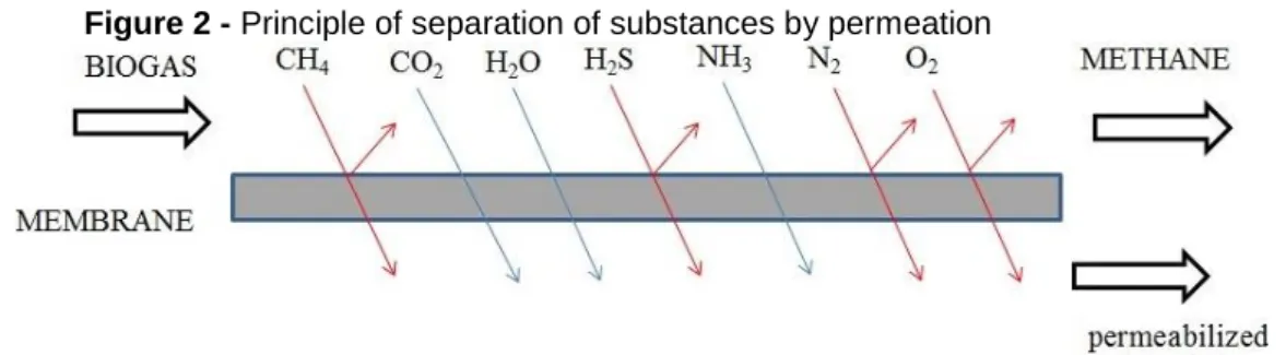
Membrane technology, especially gas permeation processes, are a relatively new process for the treatment and conditioning of gas (Figure 2). As previously de-scribed, the performance of a membrane is characterised mainly by its permeability - the product of the solubility and diffusion coefficients and their separation characteris-tics - the ratio of the permeability of gases to each other - which as a rule can only be determined in experiments (INOVAGRID, 2016); PROBIOGÁS, 2016).
Figure 2 - Principle of separation of substances by permeation
It is a more efficient process, in economic, energetic and technical terms, when compared to conventional processes, as well as presenting greater flexibility in its use (the relatively small apparatus). In this type of separation, the transport of each component occurs by a gas current, by partial pressure difference and by the component's dependence on the permeability of the membrane material, where the material of choice will depend on the solubility and diffusivity (temperature, pressure and nature) of the gaseous components present the gas to be filtered. A carrier is sometimes used to help the transmission (MARIN, 2011; LLANEZA et al., 2010; KIDA et al., 2018). In the case of CH4 with high purity, the permeability must be high.
A solid membrane constructed of cellulose acetate polymers is 20 and 60 times more permeable to CO2 and H2S, respectively, than to CH4. The pressure required by the
process is between 25 and 40 bar and the process can be carried out in two ways: gas–gas or gas–liquid (MORERO et al., 2010; JARDIM, 2013; SCHOLZ et al., 2013; HARASIMOWICZ et al., 2007; ROSSI, 2014). The durability and efficiency of the membrane can be improved by opting for biogas pre-treatment prior to membrane injection through the separation of dust and aerosols, drying and desulphurisation (INOVAGRID, 2016).
According to studies, the use of polymer membranes has shown good results, reaching increases in the percentage of CH4 of mixtures from 55–85% to 91–94.4%.
There are, however, many developments in this area, in order to optimise the entire process and minimise CH4 losses, thereby assessing performance and operating
costs. As these membranes separate CO2, this capture can also be used for recovery
in the industrial process in which it is installed (JARDIM, 2013; HARASIMOWICZ et al., 2007; BRACCIO et al., 2011).
Nevertheless, it should be noted that membrane absorption is an emerging and promising process for CO2 absorption since it integrates the advantages of
Compared with conventional chemical absorption, membrane absorption has several superior characteristics, such as a much smaller footprint, higher operational flexibil-ity and predictabilflexibil-ity, lower risks of flooding, foaming and channelling, and lower op-erational costs. As a result, membrane contactors combining chemical absorbents have been employed for biogas upgrading (CO2 absorption) (HE et al., 2018). To
im-prove the absorption efficiency, hollow fibre membrane contactors (HFMCs) have been intensively studied in recent decades as alternatives to conventional packed column technologies (LI et al., 2018).
Studies show the growth of biogas biogas purification research in the last 5 years. It is observed that there was an increase in the number of publications in this area of study from 2014 to 2016 (average of 30 publications). However, from 2016 to 2018 there was a slight decline, which was not as significant, and by 2018 there were 23 publications.
According to Probiogás (2016), the disadvantage of using the membrane pro-cess is that there are very few facilities for the treatment of natural gas and biogas to date. Thus, operational experience and information on this process cannot be used. An argument in favour of membrane technology is the simple structure, easy, almost maintenance-free and uncomplicated handling of the process and its high operational safety. With this, the cleaning of even small volumes of gas is possible and economi-cally sensible, without disproportionally extrapolating the specific costs. However, most of the costs of this process occur due to the great work of compression. Me-thane losses are still high with the application of membranes for the treatment of CH4,
which also represents a problem today. Still, membrane processes in the near future can be used economically in combination with scrubbers and adsorption facilities for the prior cleaning of process flows. Currently, the membrane separation processes are in the phase of introduction onto the market.
According to Pinheiro (2015), the use of gas separation membranes in indus-try requires a high energy demand for both chemical selection and chemical trans-formation. Chains with only one component featuring pure gas, without contaminants, are extremely valuable in industry. They serve several applications, since they have well-known physical and chemical properties, unlike blends with two or more compo-nents, the behaviour of which needs to be studied in more detail.
fa-sidual components in biogas such as H2S or water vapour permeate through
mem-branes more rapidly than CO2. In this way, the membranes can remove CO2, H2S
and water vapour in a single step if sufficient pressure is guaranteed in the flow. For CO2 separation from CO2/CH4 gas mixtures, various membranes have
been investigated, including organic, inorganic, the metal–organic framework, and mixed-matrix membranes (KIDA et al., 2018).
In the literature, numerous applications of membranes in the treatment of gas-es with H2S (g) are reported. Around the world, there are about 200 treatment plants
that incorporate membranes in the removal of CO2 (g) and H2S (g) (VIERA et al.,
2015; BENITO, 2004).
Kadam and Panwar (2017) shows that the method that separating impurities such as CH4 and CO2, using membranes, works on the principle of pressure
differ-ence between gases. The membranes that are available for separation can be grouped into two main types: high- and low-pressure membranes. The high-pressure membrane separation process is usually operated at a pressure less than 20 bars and is operated at 8-10 bars in some systems. In the multistage process, the biogas is updated to a CH4 content of more than 96%. Carbon molecular sieve (CMJ) hollow
fibre membranes have been investigated for CO2/CH4 separation up to 1000 psi. The
mechanical permeance of CMJ membranes under high pressure was encouraging and relevant for the removal of CO2 from natural gas. In multistage membrane
sepa-ration, the waste gases from the first stages are recycled within the process to enrich the CH4 content of the final gas output. Low pressure membrane systems work at
pressures close to atmospheric. It is found that using capillary module with polyamide membranes makes it possible to achieve membrane enrichment in a single module, while multistage or hybrid systems should be used to prevent CH4 losses. A highly
effective CO2 selective polyvinyl amine/polyvinyl alcohol membrane was investigated
for biogas upgrade. The process, with four different membrane module configurations with or without recycling, was evaluated; it was found that the 2 stages cascade with the recycling configuration was the most optimal of the four processes.
In their studies, Scholz et al. (2013), Chmielewski et al. (2010) and Cerqueira et al. (2010) presented the most commonly used and suitable membranes for the treatment of natural gas, which are polyimide and cellulose acetate membranes. Pol-yimides have a high permeability compared to the other polymers used in CO2
cellulose acetate (CA). The first industrial plants using CA were installed in the 1980s and currently dominate the natural gas processing market. However, the major con-cern with CA membranes is their susceptibility to CO2 plastification, which reduces
their mechanical stability while decreasing their separation performance and increas-ing material agincreas-ing. It is increasincreas-ingly apparent that CA is used only as a porous sup-port structure in asymmetric polymer membranes. This is due to the low cost of CA production and the well-known method of manufacture. Currently, there is a great effort to develop materials that are resistant to plasticisation with greater permeability to CO2 and selectivity for CH4. However, cellulose acetate membranes are sensitive
to water vapour and, without pre-treatment, cellulose acetate membranes are not suitable for the modernisation of biogas. In the work of Jeon and Shin (2017), the highly selective cellulose acetate (CA) asymmetric hollow fibre membranes were prepared via a dry/wet spinning process with NIPS (non-solvent-induced phase sepa-ration) from dope solutions containing NMP as a solvent and tetrahydrofuran (THF) and ethanol (EtOH) as a non-solvent and coated with polydimethylsiloxane (PDMS). The prepared CA hollow fibre membranes showed excellent selectivity about 37.0 for CO2 and CH4 under optimised conditions (23 wt.% CA, 62 wt.% NMP, 10 wt.% THF,
5 wt.% EtOH, and 15 cm air-gap) and 5 wt.% PDMS coating. The newly prepared CA hollow fibre membranes were applied to CO2/CH4 separation. The newly prepared
CA hollow fibre membranes showed much better performance than the existing commercial membranes.
In addition, the study by Chmielewski et al. (2013) showed that the use of an asymmetric hollow fibre polyimide module for the biogas purification was an efficient method (low energy consumption, small concepts and a simple separation module), making it possible to achieve an area three times larger per unit volume than spiral wound modules. Belaissaoui et al. (2016) presented an evaluation of the potentiali-ties of using a membrane contactor based on a dense skin Poly (Phenylene Oxide) (PPO) hollow fibre module for CO2 absorption from biogas by pressurised water
through simulations and experiments. In this system, the liquid flowing on the shell-side is in direct contact with the dense skin, thus enabling pressurisation and avoid-ing membrane wettavoid-ing in order to maintain stable absorption performances.
Li et al. (2018) investigated CO2 removal from biogas (containing 40% CO2
aque-phobic PTFE (polytetrafluoroethylene) membrane fibres (with a water contact angle of 158.4° and sliding angle of 1.3°) were fabricated by spraying silica nanoparticles on the membrane surface and then used in the membrane module for absorption ex-periments. The results indicated that, when using aqueous K2CO3 solutions as an
absorbent, the modified superhydrophobic membrane used in this study was able to prevent membrane wetting even at pressurised conditions up to 10 bars. This work showed that the superhydrophobic membranes modified by spray-deposition tech-nique have great potential for application in HFMC to avoid membrane wetting for biogas purification under pressurised conditions.
Harasimowicz et al. (2007), as well as Chmielewski et al. (2013), showed that the use of polyimide which is formed by aromatic rings and functional groups with a large volume, which act like molecular sieves, as a material for membranes in gas separation is reasonable. Due to the high glass transition temperature and low solu-bility of the polymer, it is possible to apply these in a wide range of temperatures and pressures (in particular, polyimides have robust mechanical properties to withstand high pressure processes). They are characterised by long durability and high chemi-cal stability. The polyimide membranes are less susceptible to plasticisation by car-bon dioxide than CA membranes; therefore, they are supposed to be more suitable for CO2 separation. Other polymers have an even higher selectivity for the CO2/CH4
gas mixture. However, the gas permeability obtained for them was two orders lower in comparison with that for a polyimide membrane. With the application of polyimide membranes, CH4 enrichment in a single step is possible, which makes this type of
membrane very attractive from technical and economical perspectives.
Pinheiro (2015) and Miltner et al. (2008) described the order of permeabilities of biogas components in polyimides, for example, to be water, carbon dioxide, hy-drogen sulphide, oxygen and long chain alkanes. Therefore, depending on the pur-pose of the biogas use, the process employs some pre-treatment steps that must be performed before the feed gas comes into contact with the membrane. The risk of not pre-treating the feed gas is the plasticisation of the membrane material, swelling and compaction, and the possible competition between the gases that permeate it.
In the studies of Harasimowicz et al. (2007), Pinheiro (2015), Kayhanian and Hills (1998) and Guha et al. (1991), various membrane materials of different compo-sition were tested for their permeability to CH4, CO2 and H2S; among these were
both passive and facilitated transport. They also analysed the flow pattern in gas permeation modules and module arrangements. The optimal module arrangements for two important cases, the enrichment of oxygen from air and the production of me-thane from biogas, are one- or two-stage cascades.
Rossi (2014) showed that membranes are normally used for the purification of biogas circulation. Each type of gas has a different rate of diffusion into the solid from which the membrane is formed. In the materials used, methane distribution is much slower than that of CO2 or H2S. The transport is regulated by the permeability of the
component to be removed within the membrane material.
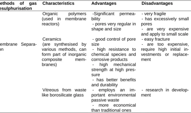
Viera et al. (2015) discussed the desulphurisation method, which is based on the diffusion of some compounds as they pass through a selective membrane, gen-erally constructed with porous organic polymers in various configurations and is ex-tremely fine (in the order of microns). This has been used to selectively remove cer-tain gases that are present in combustible gases in general. The membranes used to date are very fragile and have pores that are too small, so it is necessary for the gas entering the membranes to be cleaned of particulate material in suspension. These systems are expensive and are generally suitable for small scale applications (table 3), although they have been successful in pilot scale studies using polyamide and cellulose acetate membranes, which have shown to be effective at removing CO2 (g)
and H2S (g) of the biogas.
Table 3 - Biogas desulfurization methods, characteristics, advantages and disadvantages (VIERA et al., 2015)
Methods of gas desulphurisation
Characteristics Advantages Disadvantages
Membrane Separa-tion Organic polymers (used in membrane reactors) -Significant permea-bility
- pores very regular in shape and size
- very fragile
- has excessively small pores
- are very expensive and apply to small scale Ceramics
(are synthesised by various methods, can form part of inorganic composite mem-branes)
- good control of pore size
- high resistance to chemical species and corrosive products
- high mechanical strength at high pres-sure
- has better benefits and durability
- easy fracture
- are too expensive, require high initial in-vestments or replace-ment
Vitreous from waste like borosilicate glass
- employs an im-portant environmental passive waste - more economical - research in develop-ment
In the case of H2S, Harasimowicz et al. (2007) and Morero et al. (2010)
re-ported that it was possible to achieve the enrichment of CH4 from concentrations of
55–85% to 91–94% when using capillary modules with polyamide membranes. The membrane material is resistant to low concentrations of acid gases and ensures the reduction of H2S and the concentration of water vapour. Tilahun et al. (2017)
pre-sented the use of a polydimethylsiloxane (PDMS) membrane contactor for the selec-tive removal of H2S from the biogas. Experiments were carried out to evaluate the
effects of different pH of absorption liquid, biogas flow rate and temperature on the absorption performances. A tubular PDMS membrane contactor was tested for the first time to remove H2S from biogas under slightly alkaline conditions and the
sug-gested process could be promising for real scale applications.
Kadam and Panwar (2017) reported the use of permeselective membranes for the removal of CO2 and H2S; ultrafine polymer membranes were found to be
ex-tremely effective for purification. The facilitated transport membranes in which the reversible chemical reaction occurs are perfect for CO2 absorption. The permeation
rates were relatively low and less attractive for the purification of biogas. Liquid gas adsorption is a newly developed process that uses microporous hydrophobic mem-branes. CO2 and H2S dissolve in the liquid while the methane remains available for
use.
Chmielewski et al. (2013) mentioned that another new method of gas separa-tion is represented by ionic-liquid membranes (major advantages: high fluxes through membranes and very good selectivity). It seems that membrane technology has the greatest potential. Compared to conventional methods, membrane separation has many advantages, including low operating costs, an easy-to-handle system with pro-cess flexibility and no additional chemicals.
In recent years, metal-organic frameworks (MOFs) have attracted vast re-search interests as fillers for mixed-matrix membrane (MMM) fabrication owing to their large pore volumes and tuneable functionalities that can lead to high permeabil-ity and selectivpermeabil-ity in the resulting membranes, respectively. Gong et al. (2017) re-ported a study where nanocrystals of Zn(pyrz)2(SiF6) (or SIFSIX-3-Zn) metal-organic
framework were synthesised by an easy sonochemical method and incorporated into a polyimide membrane to achieve an excellent CO2/CH4 separation performance.
Zn(pyrz)2(SiF6) nanocrystals selectively took up a large amount of CO2, even at low
Zn(pyrz)2(SiF6) is an ideal filler to improve the CO2/CH4 separation performance of a
polymer membrane via the selective transport of CO2 over CH4. Subsequently,
high-quality mixed-matrix membranes that are free of filler/polymer interfacial voids were successfully fabricated by employing house-made polyimide as a polymer matrix. Binary CO2/CH4 mixture gas permeation tests revealed that both CO2 permeability
and CO2/CH4 selectivity of mixed-matrix membranes, especially for the membrane
with 20 wt% filler loading, were significantly improved compared to those of pure pol-ymeric membrane owing to the selective uptake of CO2 and transport by
Zn(pyrz)2(SiF6) crystals. As a result, a high performance surpassing the upper bound
limit for polymeric membranes was achieved.
The incorporation of nanocrystals can be used to significantly enhance CO2
permeability (up to 60%) and contributes to improved CO2/CH4 selectivity (up to 28%)
compared with those of pure polymeric membrane. Such significant improvements in the mixed-matrix membrane’s CO2/CH4 separation performance and mechanical
strength suggest a feasible and effective approach for potential biogas upgrading and natural gas purification (LI et al., 2018). For Chen et al. (2018) and Kanehashi et al. (2018), MMMs can increase the permeability and/or selectivity of polymeric mem-branes and can reduce membrane aging, also the memmem-branes containing carbon or porous organic nanoparticles were the most stable.
Other citations of recent works, for example ultrathin MMMs containing two-dimensional (2D) fillers, are highly sought after due to their good performance in gas separations. Cheng et al. (2017) reported the preparation of PIM-1 (Polymers of in-trinsic microporosity)-based ultrathin MMMs containing 2D metal-organic framework (MOF) nanosheets using a spin coating method. The lamellar structure of the 2D lay-ered MOF filler (copper 1,4-benzenedicarboxylate nanosheets, CuBDC-ns) enlarges the contact area between fillers and the polymer matrix, leading to the formation of dense MMMs. The centrifugal force generated during the spin coating process helps to horizontally align these CuBDC-ns, increasing the gas diffusion resistance across the membrane. The influence of membrane thickness and filler content on the sepa-ration performance of CO2/CH4 mixture is examined and discussed. In conclusion,
the newly developed ultrathin MMMs may have great potential in CO2/CH4
separa-tions, such as in natural gas purification and biogas upgrading. In the study of Kida et al. (2018), dense and thin pure silica CHA-type zeolite (Si-CHA) membranes were
CO2/CH4 separation performance under dry and humidified conditions. Si-CHA
membranes with ultra-high permeance were greatly affected by performance sup-pression due to concentration polarisation under high pressure and low feed-rate conditions. Under high feed-rate conditions at 298 K and a feed pressure of 0.1 MPaG, the CO2/CH4 selectivity was 130 with a CO2 permeance of 4.0×10⁻⁶ mol/(m2s
Pa) for an equimolar CO2/CH4 dry gas mixture. The presence of water vapour
signifi-cantly reduced CO2 permeance, but the performance improved as feed pressure
in-creased. The CO2/CH4 selectivities at high pressure with and without water vapour
were essentially the same.
However, the performance of the membranes varies greatly, depending on the configurations (stages, for example, pressure, loops) and the original design adopted by each manufacturer. Often, a single phase membrane unit cannot give the desired quality of the product or the energy savings required to make the application feasible (PINHEIRO, 2015; THRÄN et al., 2014; PABBY et al., 2009). However, like any other separation technique, the membrane is not able to fully purify the biogas with com-plete separation of the components. The exit gas, rich in carbon dioxide, also con-tains small amounts of methane (usually 2 to 3% of the biomethane produced) and other separate substances. One of the feasible and practiced solutions in some plants is the implementation of a recycling of this stream of CO2 with a little methane
to a gas engine (CHP) attached to the biogas plant. Thus, methane is not lost or emitted into the atmosphere, but is burned and its chemical energy is used to pro-duce heat and energy (PINHEIRO, 2015; MILTNER et al.,2008).
5 COMPARATIVE ANALYSIS OF PURIFICATION OF BIOGAS BY MEMBRANE SEPARATION TECHNOLOGY IN PRESENT
As already mentioned, purified biogas not only helps in reduction in GHG emissions but also has other environmental benefits. Upgraded biogas emits less hydrocarbons, nitrogen oxide and carbon monoxide compared to gasoline or diesel (SAHOTA et al., 2018).
To date, several methods have been developed to improve CO2/CH4
separa-tion performance. However, these are still in their nascent stage and more efforts are needed to bridge the knowledge gap between pilot tests and large-scale operations (SAHOTA et al., 2018).
In recent years, membrane separation technology has received more and more attentions, since membrane process is energy efficient, environmentally friendly and easy to scale up (XU et al., 2019).
The researches indicate that the optimization of operating process designs could improve the separation performance, reduce the energy consumption and de-crease the cost of membrane separation systems (SAHOTA et al., 2018; XU et al., 2019; SAMARASINGHE et al., 2018). Membrane separation technology is one of the most promising technology for CO2 capture from flue gas, when taking into account
the benefits of membrane processes, including simplicity of operation, modular con-struction, small footprint, no hazardous by-product emissions. However, CO2 capture
from flue gas based on membrane process is still not fully explored, since the sepa-ration targets proposed by U.S. Department of Energy (DOE) with product purity higher than 95% and recovery higher than 90% are too difficult to achieve with low energy consumption and capture cost. The low CO2 concentration and low pressure
in flue gas are responsible for the difficulty of separation process, high energy con-sumption and capture cost (XU et al., 2019).
As the time goes by, novel membrane materials developed according to the requirement proposed by process optimization with increased selectivity and/or per-meance will accelerate the industrialization of membrane process in the near future (SAHOTA et al., 2018; XU et al., 2019; SAMARASINGHE et al., 2018).
Membrane technology has its own advantages like the system is generally compact and lighter, plant requires small and less skilled labor, requires less mainte-nance. Also, the performance of membrane separation is independent of the concen-tration of volatile organic compounds (VOCs) which is not the case in other upgrada-tion technologies (SAHOTA et al., 2018; SCHOLZ et al., 2013). Apart from these ad-vantages, there are a few disadvantages also like high cost of membrane, degrada-tion of membrane with time and damage caused to the membrane because of the vibrations caused by colloidal solids (SAHOTA et al., 2018).
Understanding this phenomenon will help in membrane separation of gas mix-tures without the need of membrane regeneration thereby reducing the cost involved in membrane separation technology (SAHOTA et al., 2018). One of the major issues in biogas upgradation is the high cost involved in obtaining methane rich biogas by separation of CO2 (SAHOTA et al., 2018; KADAM, PANWAR, 2017).
According to data from Sahota et al. (2018), in relation to investment and maintenance /cost (€/year) for 1000 m3, for membrane separation, the investment
cost is high, but the operational cost is relatively low. Comparing with the techniques of water scrubbing and physical absorption (basis of operation: physical absorption), chemical (basis of operation: absorption) and membrane (basis of operation: per-meation), these were from 10,00,000 and 15,000 – 39,000; 20,00,000 and 59,000; 20,00,000 and 25,000, respectively.
Cost is one of the crucial factors in determining the optimal solution; however the cheapest solution is not always the best solution. Also, there is a lack of data re-lated to costs for the emerging technologies (KADAM, PANWAR, 2017; SAHOTA et al., 2018).
Although, continuous attempts have been made to develop membranes that can overcome the drawbacks of types of membranes and the optimal technology may vary as per requirements.
Inorganic membranes are an area of interest for many researchers because of their higher values of permeability and selectivity. The ability of these membranes to withstand harsh environmental conditions, make them eligible for CO2/CH4
separa-tion (SAHOTA et al., 2018; CHEN et al., 2018). Due to high thermal and chemical stability, inorganic membranes provide higher separation performance with longer operational life at complicated fabrication process and higher cost. Fabrication cost of inorganic membranes is more than polymeric membranes. Because of these disad-vantages, inorganic membranes find a limited application at commercial scale. the improvement in permeability of porous membrane is a challenge in case of inorganic membranes (SAHOTA et al., 2018; CHEN et al., 2015).
Polymeric membrane have the advantages of ease of scaling-up and lower fabrication cost. However, phenomena like plasticization, compaction and ageing cause the deterioration in performance of polymeric membrane under harsh condi-tions (i.e., high pressure, high CO2 concentration) (SAHOTA et al., 2018; CHEN et
al., 2018). A saturation stage has been achieved in research despite the extensive efforts done to enhance the permeability and selectivity of polymeric membranes (SAHOTA et al., 2018).
Mixed matrix membranes are heterogeneous and fabricated by mixing inor-ganic filler into polymer matrix to attain superior permeability and selectivity at afford-able pricing and easy scalability. This is done in order to integrate the advantages