MAC Regenerative Analysis
Of
Wireless Ad-Hoc Networks
Por
Luís Filipe Dias de Sousa
Dissertação apresentada na Faculdade de
Ciências e Tecnologia da Universidade Nova de
Lisboa para obtenção do grau de Mestre em
Engenharia Electrotécnica e de Computadores.
Orientador: Professor Rodolfo Oliveira
Lisboa
2010
Preface
I would like to express my gratitude to my advisors Professor Rodolfo Oliveira,
Pro-fessor Yevgeni Koucheryavy and Researcher Sergey Andreev. It was a pleasure to work
on such an interesting topic and to learn new things from them all. I really appreciate
Professor Rodolfo availability and patience to answer all my questions. It was very kind of
him to accept being my supervisor under my exchange studies period. I feel very grateful
for the opportunity that Professor Yevgeni Koucheryavy gave me to work in the
communi-cations research group and for supporting all technical material needed. I really appreciate
the patience that Researcher Sergey Andreev had with me in all this learning process and
for all the hours that he spent with me explaining the contents needed to this thesis. I
would also like to thank Professor Jarmo Harju for all his support.
I dedicate this thesis to my parents and my sister for their support and encouragement all
over this process of making this work abroad. A special thanks to all my Portuguese and
international friends that always support me.
Resumo
O IEEE 802.11 ´e uma tecnologia em expans˜ao por todo o mundo, sendo hoje em
dia utilizada por centenas de milh˜oes de utilizadores. Apesar do elevado n´umero de
uti-lizadores, nem todos precisam da mesma Qualidade de Servi¸co (QoS). Deste modo, a
diferencia¸c˜ao de servi¸co ´e um factor importante e, por essa raz˜ao, deve ser considerada
em modelos matem´aticos que modelam o desempenho da rede. Al´em disso, os utilizadores
comunicam tipicamente atrav´es de conex˜oes ponto-a-ponto (esquema de transmiss˜ao
uni-cast) e conex˜oes ponto-multiponto (esquema de transmiss˜ao broadcast). A co-existˆencia
de tr´afego unicast e broadcast influencia o desempenho da rede e a sua importˆancia n˜ao
deve ser negligenciada. Estes factos motivam o trabalho apresentado nesta disserta¸c˜ao, o
qual afere a sua importˆancia no desempenho da rede.
Esta tese descreve um modelo que modela o comportamento do MAC (Medium Access
Control) usado nas redes baseadas na tecnologia IEEE 802.11. Este ´e o primeiro passo
para desenvolver um modelo que considera grupos de utilizadores que usam diferentes
parˆametros MAC e a coexistˆencia de dois diferentes esquemas de transmiss˜ao (unicast e
broadcast).
Por fim, o modelo apresentado ´e validado atrav´es de simula¸c˜oes, caracterizando-se a sua
precis˜ao e algumas propriedades das redes s˜ao discutidas.
Abstract
The IEEE 802.11 is a fast growing technology all over the world. This growth is
essen-tially due to the increasing number of users in the network. Despite the increasing number
of users, not all of them need the same quality of service. Thus, service differentiation
is an important aspect that shall be considered in mathematical models that describe
network performance. Moreover, users typically communicate using point-to-point
con-nections (unicast transmission scheme) and point-to-multipoint concon-nections (broadcast
transmission scheme). The co-existence of unicast and broadcast traffic impacts the
net-work performance and its importance cannot be neglected in the netnet-work performance
evaluation. This motivates the work presented in this thesis, which characterizes the
net-work accounting for these important parameters.
This thesis formulates a model to describe the behavior of the medium access control used
in IEEE 802.11-based networks. This is the first step to develop a model that considers
both different groups of users configured with different medium access control
parame-ters and the co-existence of two different transmission schemes (unicast and broadcast).
The model also assumes a finite number of retransmissions for unicast packets and it is
confirmed that several models already proposed in other works are especial cases of the
proposed model.
Finally, a theoretical validation of the model is done as well as some simulations to assess
its accuracy and, some realistic network features are discussed.
List of Abbreviations
ACK – Acknowledgement;
AIFS – Arbitration Interframe Space;
BA – Block Acknowledgment;
BEB – Binary Exponential Backoff;
BC – Binary Exponential Backoff Counter;
CSMA/CA – Carrier Sense Multiple Access/Collision Avoidance;
CS – Carrier Sense;
CTS – Clear to Send;
CW – Contention Window;
DCF – Distribution Coordination Function;
DIFS – DCF Interframe Space;
ECDA – Enhanced Distributed Channel Access; EIFS – Extended Interframe Space;
FDMA – Frequency Division Multiple Access;
FCS – Frame Check Sequence;
GA – Geometric ALOHA;
GA-IT – Geometric ALOHA with Immediate Transmission; GA-NIT – Geometric ALOHA with Non-Immediate Transmission;
IFS – Interframe Space;
MAC – Medium Access Control;
MANET – Mobile Ad Hoc Network; NAV – Network Allocation Vector; ns-2 – Network Simulator - 2;
PHY – Physical Layer;
QoS – Quality of Service;
RCP – Retransmission Control Procedure;
RMA – Random Multiple Access;
RTS – Request to Send;
SIFS – Short Interframe Space; TXOP – Transmission Opportunity; TDMA – Time Division Multiple Access;
UA – Uniform ALOHA;
WLAN – Wireless Local Area Network;
Contents
Preface i
Resumo iii
Abstract v
List of Abbreviations vii
1 Introduction 1
1.1 Problem Statement and Motivation . . . 2
1.2 Objectives . . . 4
1.3 Thesis Outline . . . 4
2 Related Work 7 2.1 IEEE 802.11 MAC-Layer Protocols . . . 8
2.1.1 Distribution Coordination Function . . . 8
2.1.2 Enhanced Distributed Channel Access . . . 12
2.2 Background . . . 15
2.3 System Model Assumptions . . . 20
2.4 Classification of Protocols . . . 23
2.5 Analytical Model Requirements . . . 25
3 Slotted ALOHA Protocol: Simple Analysis 27 3.1 Geometric ALOHA . . . 30
3.1.1 Saturated Traffic Conditions . . . 30
3.1.2 Non-Saturated Traffic Conditions . . . 31
3.2 Uniform ALOHA . . . 43
3.3 Conclusions . . . 49
4 BEB Protocol: Simple Analysis 51 4.1 Regeneration Cycle Approach . . . 53
4.2 Lossless System Operation . . . 56
4.2.1 Model from Kwak et al. . . 56
4.2.2 Model from Bianchi . . . 59
4.3 Lossy System Operation . . . 61
4.3.1 Model from Andreev et al. . . 61
4.3.2 Proposed Model . . . 64
4.4 Conclusions . . . 67
5 BEB Protocol: Advanced Analysis 69 5.1 Network Heterogeneity . . . 70
5.2 Unequally-Slotted System . . . 74
5.3 EDCA Simplified Model . . . 78
6 Model Validation 81 6.1 Transmission Probability Validation . . . 82
6.2 Discussion . . . 85
7 Conclusions 91 7.1 Synthesis . . . 91
7.2 Conclusions . . . 92
7.3 Future Work . . . 93
List of Figures
1.1 Consequences in success probability for IEEE 802.11b considering the
co-existence of traffic in the network. . . 3
2.1 Time intervals relationships of DCF/EDCA. . . 9
2.2 Unicast basic access scheme mechanism. . . 11
2.3 Unicast RTS/CTS access scheme mechanism and NAV setting. . . 11
2.4 EDCA reference model. . . 13
2.5 Generic network topology. . . 20
2.6 Classification of multi-access protocols. . . 23
3.1 Basic user sate diagram. . . 29
3.2 System implementation for simulation purposes. . . 29
3.3 Generic Markov chain for ALOHA protocol. . . 32
3.4 Arrival and departure rate for GA-IT. . . 35
3.4 Arrival and departure rate for GA-IT. . . 35
3.5 Stationary probability vector for GA-IT. . . 37
3.5 Stationary probability vector for GA-IT. . . 37
3.6 Performance of different protocol implementations. . . 41
3.6 Performance of different protocol implementations. . . 42
3.6 Performance of different protocol implementations. . . 42
3.7 Multi-access using uniform ALOHA forWmax = 4. . . 43
3.8 Difference between UA and GA considering immediate transmission. . . 44
3.8 Difference between UA and GA considering immediate transmission. . . 45
3.8 Difference between UA and GA considering immediate transmission. . . 46
3.9 Difference between uniform distribution function and geometric distribution function. . . 47
3.10 Difference between UA and GA considering non-immediate transmission. . 47
3.10 Difference between UA and GA considering non-immediate transmission. . 48
3.10 Difference between UA and GA considering non-immediate transmission. . 48
4.1 Regeneration cycle concept for an infinite number of BEB stages and an infinite number of (re)transmissions. . . 53
4.2 Regeneration cycle concept for a finite number of BEB stages and a finite
number of (re)transmissions. . . 54
4.3 Capture effect consequences on fairness for a network with 40 users. . . 58
4.3 Capture effect consequences on fairness for a network with 40 users. . . 58
5.1 General topology for a network with groups of heterogeneous users. . . 70
5.2 Channel probabilities. . . 72
5.3 Unequally-slotted system in IEEE 802.11-based networks. . . 74
5.4 Network configuration for EDCA evaluation. . . 78
6.1 Transmission probability simulations results. . . 83
6.1 Transmission probability simulations results. . . 83
6.2 BEB freezing counter assumptions. . . 87
6.3 Behaviour of BEB counter in model and simulations assumptions. . . 88
List of Tables
3.1 GA-IT transition equations description. . . 34 3.2 GA-NIT transition equations description (Considering Type-1 system). . . . 39 3.3 GA-NIT transition equation description (Considering Type-2 system). . . . 40
5.1 Heterogeneous model parameters. . . 71
6.1 Parameters used in all validation results. . . 81 6.2 Parameters used in ns-2 simulator for one homogeneous group pt validation. 82
6.3 Parameters used in ns-2 simulator forpt validation, considering a
heteroge-neous scenario with three groups of homogeheteroge-neous users. . . 84 6.4 Validations results for pt considering a heterogeneous scenario with three
groups of homogeneous users. . . 84 6.5 BEB parameters used for the simplified EDCA approach. . . 85 6.6 Validations results forpt considering EDCA simplified scenario. . . 85
Chapter 1
Introduction
The Wireless Local Area Networks (WLANs) based on IEEE 802.11 standard [1] are
a fast growing technology all over the world. This kind of networks is easy to deploy and
it provides an effective low cost way to achieve wireless data connectivity between devices.
There are special cases of WLANs such asAd Hoc networks andMobile Ad Hoc Networks
(MANETs). An Ad Hoc network is a self-configuring network of devices connected by
a wireless link. What differentiates MANETs from Ad Hoc networks is the mobility of
devices in the network. These emerging and fast propagation technologies bring the need
to evaluate the network performance in order to support more users and to exploit limited
wireless bandwidth resources more efficiently. The lack of infrastructure of these wireless
technologies makes theMedium Access Control (MAC) more complex.
Typically, Ad Hoc networks rely on two kinds of traffic: Unicast and Broadcast.
Uni-cast traffic is used in point-to-point connections whereas that broadUni-cast traffic is used in
point-to-multipoint connections. As these two types of traffic serve different purposes and
generally coexist within a network, they shall not be neglected.
The number of users in WLANs is increasing, however not all of them have the same
necessities in terms of channel resources consumption. For this reason, a traffic
differenti-ation is needed in nowadays networks. This introduces the notion of priority in the access
to the radio channel. Thus, a group of users can have the possibility to access the channel
with higher probability than others. For instance, real-time traffic needs a higher priority
to access the channel than other types of traffic.
Due to the traffic differentiation requirement,Enhanced Distributed Channel Access(EDCA)
[2] extended the Distributed Coordination Function (DCF) of legacy IEEE 802.11 [1] in
order to provideQuality of Service (QoS) for different types of users. This extended
ver-sion of the protocol provides QoS levels for different types of traffic and it allows for the
optimization of network resources.
The focus of this work is to propose a model that studies the IEEE 802.11 MAC
perfor-mance (under the conditions presented in section 2.3). The model shall account for the
mixture of traffic, groups of heterogeneous users with different QoS requirements and a
finite number of (re)transmissions. Consequently, a simplified EDCA model is also
stud-ied. The simplified EDCA model cannot fully capture the complex behavior of EDCA,
however it gives a lower bound on the network performance that takes into account some
network parameters that arbitrate users’ channel access priority.
1.1
Problem Statement and Motivation
In [3] it is shown that broadcast traffic is a critical parameter that strongly affects
the network throughput. According to Oliveira, this effect is essentially due to two main
reasons. Firstly, broadcast and unicast traffic rely on different transmission schemes.
What really differentiates these schemes is the unicast dependency on receiver’s
acknowl-edgement. This acknowledgement-based transmission scheme allows the data frame to be
retransmitted when an attempt fails (due to noisy channel, interference between
simulta-neous transmissions, etc). On the contrary, broadcast transmission scheme is unreliable.
The sender has no way to know whether the data frame was received by the recipients or
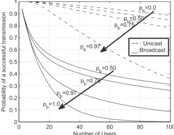
not. Figure 1.11 depicts the probability to successfully transmit a frame when different
amounts of broadcast traffic are used in the network. The consequences of this traffic
co-existence is that with the increasing broadcast traffic generation, the aggregated network
data frame success probability of transmission drops.
Secondly, broadcast transmission frames are typically sent with a lower transmission rate.
This difference of transmission rates influences the channel throughput because the
broad-cast data frames need a larger portion of time to be sent. When more than one user
trans-1Like it is explained in [3],p
1.1. PROBLEM STATEMENT AND MOTIVATION 3
mits at the same time, the channel utilization is limited by the frame that is transmitted
at a slower transmission rate.
0 20 40 60 80 100
0 0.1 0.2 0.3 0.4 0.5 0.6 0.7 0.8 0.9 1
Number of Users
Probability of a successful transmission
pb=0.0 pb=0.50 pb=0.75
p b=0.97 p b=0.50 p b=0.75 p b=0.97 p b=1.0
−− : Unicast __:Broadcast
Figure 1.1: Consequences in success probability for IEEE 802.11b considering the co-existence of traffic in the network.
In the literature, the influence of broadcast traffic on different groups of users
(hetero-geneity) was never studied. There is a need to come up with a model capable of evaluating
the MAC throughput performance of the traffic co-existence with groups of heterogeneous
users.
The amount of broadcast traffic in the network is a critical parameter that can degrade
the channel throughput and it shall be studied in more detail. This study is even more
important when the radio channel bandwidth is limited and the number of users is
grow-ing. Thus a novel model2 capable of describing the system is essential, since it will be
helpful to enhance the network throughput. Another relevant issue is the need of traffic
differentiation, because the users do not necessarily have the same needs in terms of
chan-nel utilization. Hence, new studies shall account for QoS and user differentiation.
There are many models for evaluating the MAC behavior but most of the works done so
far are done based on the network timings such as the idle time duration and the time
duration of a packet transmission (for successful and unsuccessful transmissions). These
timings increase the complexity of the models. Therefore, the focus of this work is to first
2In particular, this research work focus is the saturation conditions. A more detailed description of
develop a model based on the network probabilities and then extend the model to account
for the throughput.
1.2
Objectives
The main goal of this thesis is to provide a simple model to analyze the network
performance under saturated traffic conditions for the recent IEEE 802.11 standard. The
simple model shall also support heterogeneity between groups of users and consequently
present a simplified approach for EDCA evaluation.
The simple model is a tool that can be used whether to describe the network behavior
or for study possible ways to enhance the network throughput. The proposed model is
meant to be easy to compute due to its focus on channel probabilities. Moreover, channel
timings are taken into account for simpler cases. Finally, the simple model is tested against
simulations in order to study its accuracy.
1.3
Thesis Outline
The thesis is structured in seven chapters, including the introduction and the
conclu-sions chapter.
Second chapter introduces a brief state-of-the-art description of what was done in this
area and what is going to be done in this thesis. It describes the most important aspects
of IEEE 802.11 and the main related research works. This chapter also defines the main
set of assumptions that are adopted in this work. The foundations of the model explored
throughout this work are also described in this chapter.
The ALOHA protocol is analyzed in the third chapter. This is a very important chapter
since it explains how ALOHA protocol andBinary Exponential Backoff (BEB) mechanism
are related.
Chapter four describes the BEB mechanism. It formally introduces theRegeneration
Cy-cle Concept. This is the key concept used in this work and it is applied not only to the
proposed model, but also to some older works in literature. It is important to explain that
1.3. THESIS OUTLINE 5
reads”Simple Analysis”. Here, the first part of the proposed model is also deduced.
The fifth chapter is concerned with the”Advanced Analysis” of the BEB model. The word
”Advanced” in this case means that the chapter deals with unequally-slotted system and
heterogeneous groups of users. Moreover, a simplified EDCA model is also proposed. The
chapter ends with a list of hypothetical practical scenarios where the proposed model can
be used.
The model validation is done in chapter sixth through ns-2 (Network Simulator - 2). The
main reason for the proposed model mismatch are discussed.
Finally in the last chapter, the conclusions of this thesis are presented. This chapter also
Chapter 2
Related Work
This chapter provides the necessary information that the reader needs to understand
the next chapters. Firstly, the IEEE 802.11 standard aspects are introduced. Secondly,
the background section presents related research work. Next the general set of model
assumptions is described. This set of assumptions is needed because it represents a unified
view of the system. For each model studied through this thesis the relevant changes to
this set of assumptions are presented in a list to make the model scope more clear. This
has an extreme importance since the models are only valid under some certain conditions.
After the basic set of assumptions, the protocols classification is done. This is important
because this thesis deals with several different protocols, helping to clarify the type of
Random Multiple Access (RMA) being described. A RMA protocol is a set of rules that
allows users to access the channel without a centralized point of coordination. Finally the
proposed model of this thesis is introduced and its characteristics are discussed in detail.
2.1
IEEE 802.11 MAC-Layer Protocols
The most important MAC layer aspects of IEEE 802.11 standard are described in this
subsection. For a more detailed information the reader shall refer to [1] and [2]. The scope
of this section is the overview of DCF and EDCA mechanisms that allow users to access
the channel.
2.1.1
Distribution Coordination Function
In 1999, the IEEE 802.11 standard [1] was proposed to provide the features for the
Physical (PHY) layer and Media Access Control (MAC) layer. It describes the information
that these two layers provide to each other and its tasks. In what follows, little attention is
given to PHY since it is not the scope of this research work. The DCF is a medium access
protocol that allows a group of users to share the same wireless channel through the use
of a mechanism called Carrier Sense Multiple Access/Collision Avoidance (CSMA/CA)
and a Binary Exponential Backoff (BEB) mechanism.
The Carrier Sense (CS) of DCF is done though physical and virtual means. The virtual
CS is typically implemented with the exchange of two special reservation frames,Request
to Send (RTS) and Clear to Send (CTS), before the exchange of the data frames. These
two control frames have a duration field in the frame header that contains the period
of time that the medium will be busy transmitting the data frame and for the recipient
user to return theAcknowledgement (ACK) frame. The duration field is useful to prevent
the hidden users from accessing the channel while a transmission is in process. A hidden
user is a user that cannot sense the sender but can influence the receiver if it starts to
transmit a data frame. In a wireless environment a user can receive a frame that was not
addressed to it. As such, this node shall use the duration field information contained in
the header of the received frame to update the Network Allocation Vector (NAV). This
timer is just a prediction of how long the medium is expected to be busy, so the user can
defer its transmission until this timer expires. The physical CS is not a MAC function
because it is the PHY that deals with it through the analysis of the channel Signal to
Interference-plus-Noise Ratio(SINR). Finally, the user shall never transmit when weather
2.1. IEEE 802.11 MAC-LAYER PROTOCOLS 9
The time interval between frames is called theInterframe Space(IFS). Different IFS values
allow for different kinds of packets to access the medium in a different way. For instance,
an ACK frame or a CTS frame has always priority when compared with a regular data
frame. Figure 2.1 shows the difference between these xIFS times.
DIFS/AIFS
Busy
Medium SIFS
DIFS AIFS[i]
AIFS[j]
Decrementing Backoff counter as long as the medium is idle
Next Frame Higher Priority
Lower Priority
DEFER ACCESS Idle Time Slot Immediate access when
the medium is free >= DIFS/AIFS
Figure 2.1: Time intervals relationships of DCF/EDCA.
The different xIFS description can be found below:
• Short Interframe Space (SIFS): This is the shortest IFS time and it is essentially
used between the following frames: RTS-CTS, CTS-DATA and DATA-ACK. Using
SIFS between the frame exchanges prevents other users from attempting to use the
medium, which is required to wait for the medium to be idle for a longer time.
• DCF Interframe Space(DIFS): Each user having a data frame to transmit shall defer
at least a DIFS time before starting transmission.
• Extended Interframe Space (EIFS): This is the longest IFS time and it is used when
a user has received a frame that contains errors. It is possible to detect errors in a
frame each time that the MAC Frame Check Sequence (FCS) is not correct. This
IFS time is useful since the user could not understand the last received frame, and
consequently could not update the NAV timer. This avoids the user from colliding
with a future frame belonging to the current dialog. This means that all users
that received the corrupted frame wait for an EIFS while the sender waits for the
expiration of the ACK time-out.
TheArbitration Interframe Space (AIFS) time duration will be explained in the next
The BEB (mentioned in Figure 2.1) has a counter, often called Backoff Counter (BC),
and it is initiated with a random integer between zero and an initialContention Window
(CW) minus one. For each idle time slot, BC is decremented by one unit. When the
BC reaches zero the user is allowed to start the transmission. Notice that the BC is only
decremented when there is an idle slot. This means that the CS mechanism has to indicate
that the medium is idle. When a collision occurs the BEB doubles its previously used CW
and all the process is repeated again. The CW is doubled as soon as the maximum CW is
not reached. A formal description of BEB mechanism is discussed and its mathematical
formulation (including the equation for the growth of CW) is done in chapter 4.
The DCF has two different acknowledgement based transmission schemes for unicast and
one acknowledgement-free based transmission scheme for broadcast. All these schemes
assume immediate transmission after the DIFS or EIFS, conditioning on if a collision in
a channel was sensed respectively. The BEB shall be started if the user has a packet
to send but the CS indicates that the medium is busy or after a non-successful packet
transmission.
The standard also describes the post-BEB in which the BEB shall be started after each
transmission, no matter whether or not the user has packets to send. The post-BEB was
imposed in IEEE 802.11 implementations to avoid a user to capture the channel. A user
shall send a packet immediately after a DIFS, however, after a successful transmission, if
there are packets in the queue the BEB is started. Hence, by controlling the timing with
which a packet is inserted in the queue it is possible to enable immediate transmission to
all packets.
A recipient does not receive a packet correctly if it was corrupted by channel noise, channel
interference or due to multiple channel transmissions in the same time slot. Thus, a user
is ready to send a packet if the medium is idle at least for a period of time equal to DIFS,
the NAV timer shows zero, the PHY indicates that the medium is idle and the BC reached
zero.
As mentioned above, there are two mechanisms to send a unicast data frame: the Basic
Access and the RTS/CTS mechanism. The basic access mechanism and the RTS/CTS are
2.1. IEEE 802.11 MAC-LAYER PROTOCOLS 11
DIFS/AIFS
SIFS DATA
ACK
NAV DATA DIFS/AIFS
Source
Destination
Defer Access Decrement BC
As long as the medium is idle Idle Time Slot
Other Users
Figure 2.2: Unicast basic access scheme mechanism.
reservation frames. This transmission scheme is used whenever the data frame length is
equal or below a given threshold1. After sensing the medium idle for a period of time equal
to DIFS the user sends the data frame. If the recipient acquires the packet correctly, it
prepares the ACK frame. This is a 2-way handshake mechanism. The remaining users in
the network sense that the medium is busy due to PHY CS or due to NAV timer. Figure
2.2 also shows why the basic access is not always a good option for multi-hop networks.
The reason is that typically only the sender’s neighbors update the NAV timer. Hence, if
there are hidden users ready to transmit, the data frames are more likely to be corrupted
because of the simultaneous transmissions.
DIFS/AIFS RTS
CTS SIFS SIFS
DATA
ACK
SIFS
NAV (RTS)
NAV (CTS)
DIFS/AIFS Source
Destination
Other Users
Defer Access Decrement BC As long as the medium is idle
Idle Time Slot
Figure 2.3: Unicast RTS/CTS access scheme mechanism and NAV setting.
Figure 2.3 shows the RTS/CTS mechanism. After the medium is sensed to be idle for
a DIFS, a reservation frame RTS is sent. This frame contains in the information about
the total time needed to finalize the transmission. When the recipient acquires the RTS
frame, it relies on its CS function to figure it out whether there is a transmission going on
in its neighborhood. If the recipient’s CS indicates that the medium is idle, then it answers
the sender with a CTS. Notice that between the RTS and CTS there is a SIFS time. This
time is shorter than a DIFS in order to prevent other users from interfering with this
4-way-handshake. Once the sender receives the answer to its RTS, it prepares itself to
send the data frame. After receiving the data frame the recipient prepares the ACK frame
to acknowledge the correct reception of the packet. Typically the time duration of RTS
updates the NAV timer of the sender’s neighbors and the time duration of CTS updates
the NAV timer of the recipient’s neighbors.
The broadcast transmission scheme is a special case of the basic access mechanism. In
the transmission of a broadcast data frame there is no acknowledgement because there are
many candidates to send it. Thus, a packet may be lost and in this case it will never be
retransmitted. This is the reason why broadcast traffic is unreliable.
The retransmission mechanism is a characteristic of unicast traffic only. Retransmissions
attempts are done when:
• The sender transmits an RTS and does not receive the CTS as a response.
• The sender transmits a data frame and the recipient does not acquire it due to bad
channel conditions or multiple transmissions at the same time.
• The receiver sends an ACK but the sender does not receive it.
There is a maximum number of retransmissions2that a packet can suffer. If the packet
is not successfully sent after those retransmitions, it is discarded.
2.1.2
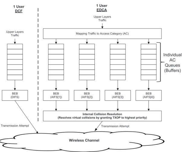
Enhanced Distributed Channel Access
The EDCA enhances the IEEE 802.11 DFC by introducing the traffic differentiation
(or QoS). The QoS is handled by introducing four separate queues for different types of
traffic. Each one of the queues, or Access Categories (AC), has a separate BEB instance
to control the access priority.
2The 802.11 specification allows for different retry limits, dot11ShortRetryLimit and
2.1. IEEE 802.11 MAC-LAYER PROTOCOLS 13
BEB (DIFS)
Mapping Traffic to Access Category (AC)
BEB (AIFS[1])
BEB (AIFS[2])
BEB (AIFS[3])
BEB (AIFS[4])
Individual AC Queues (Buffers) Upper Layers
Traffic
Upper Layers Traffic 1 User
DCF
1 User EDCA
Internal Collision Resolution
(Resolves virtual collisions by granting TXOP to highest priority)
Wireless Channel
Transmission Attempt Transmission Attempt
Figure 2.4: EDCA reference model.
The four different ACs are: Video, Voice, Background andBest Effort. Basically the
multimedia AC (Audio and Video) have higher priority to access the channel. Figure
(2.4) shows the basic model of EDCA and its difference to DCF. In EDCA the upper layer
traffic if mapped onto the right AC. Each AC has its own BEB with separate parameters
to control the access to theTransmission Opportunity (TXOP). The idea is that different
ACs contend for a TXOP instead of contending to a channel transmission. This is needed
because internal collisions can occur and, they are not real collisions but virtual collisions.
For that reason, anInternal Collision Resolution is needed. When a virtual collision
oc-curs, the internal collision resolution attributes the TXOP to the AC with higher priority.
Thus, the AC that could not obtain the TXOP behaves like if a channel collision had
occurred.
Each AC has to ensure that the medium is idle for a specific AIFS before a packet
same duration as DIFS. The AIFS times are described by equation (2.1), where AIFSN
denotes the arbitration inter-frame space number, which is different for each one of the
ACs. Each different AIFS provides an extra way to define priorities between ACs by
making the low-priority ACs deferring for a longer time than the high priority ACs.
AIF S[AC] =AIF SN[AC]∗(IdleSlotDuration) +SIF S (2.1)
The transmission schemes for unicast and broadcast of EDCA are basically the same
as DCF. However EDCA introduces a mechanism calledBlock Acknowledgment (BA). The
idea of BA is similar to the fragmentation burst in legacy IEEE 802.11, but instead of
sending several fragments of a frame the sender transmits a burst of data frames belonging
to a specific AC. There is no need for any xIFS space between the frames. The last frame
of the burst is the BA request. After receiving this BA request the sender answers with a
BA frame where it acknowledges all the successfully-received frames.
Besides an improvement to the legacy IEEE 802.11, EDCA is a contemporary protocol,
2.2. BACKGROUND 15
2.2
Background
ALOHA Protocol. The first Random Multi-Access (RMA) protocol used for wireless
communications was proposed in 1970 by Abramson [4] and it is often calledPure ALOHA.
The main idea of pure ALOHA is that whenever a user has a packet to send it shall be
transmitted. If the transmitted packet was not successfully received by the recipient,
then it is retransmitted in a future opportunity. In pure ALOHA, two or more users
can transmit at the same time corrupting each other signals. This is a serious problem
especially when the transmission of a packet interferes with the end of a packet already
being transmitted. For this reason, it was also proved in [4] that the maximum channel
capacity3 is approximately 18% when fixed packet size is used for pure ALOHA. Later,
Gaarder [5] in 1972 proved that the pure ALOHA channel capacity is always superior
when fixed packet size is used when compared with variable packet sizes. In 1973, Roberts
[6] proposed a different version of ALOHA that requires users to be synchronized. The
synchronization means that users coincide the edges of their packet transmissions with an
imaginary equal time slot boundary. This version is often called Slotted ALOHA and it
provides twice the channel capacity of pure ALOHA (see section 3.1.1 for the proof). The
increasing popularity of slotted ALOHA arose the necessity of studying models to analyze
the protocol performance and stability. Kleinrock [7] introduced in 1975 an important
model for slotted ALOHA. This model introduces a 1-D Markov Chain where users are
considered to have a single packet buffer. This work studies the throughput-delay tradeoff
by showing that the higher is the throughput, the higher is the delay. It also discusses the
protocol operation point as well as the stability points. These points are shown through
the relationship between the number of packets arriving to all users’ buffers (Channel
Ar-rival) and the number of packets sent per slot (Channel Departure). More detail about
this work is shown in chapter 3.
BEB Protocol. Lam [8] presented in 1975 a heuristic called Retransmission Control
Procedure (RCP) that he claims to be the first draft of BEB. The BEB protocol is able
to change the probability with which users access the channel by changing the CW. This
characteristic is very important because the protocol adjusts to the number of active users
3The channel capacity is the maximum possible number of packets that can be successfully sent in the
in the network. The BEB importance made several researchers studying its performance
by means of mathematical models. Research works like [9] and [10] describe Markov
Chains that are used to find the stationary equilibrium point only for saturated network.
The reason why these authors present saturated models is that it is easier when compared
to unsaturated ones. In 2003, Kwak et al.4 propose an infinite 1-D Markov Chain, where
each state of the chain represents a growth of the BEB window (often called BEB stage).
Hence, this work assumes an infinite number of BEB stages. With this approach it is
possible to calculate the saturation throughput by expressing the transmission probability
of a packet as a function of CW and the medium access delay can also be analyzed. The
simplified BEB model of [10] helps to understand some BEB proprieties (better explained
in chapter 4), but in a real system implementation there is a fixed number of BEB stages.
Back in 2000, Bianchi [9] uses an approach with 2-D Markov Chain5. One of the Markov
Chain’s dimensions is the BC and the other dimension is the BEB stage. Bianchi assumes
that in the stationary equilibrium point, theconditional collision probability of each user is
constant. This assumption was controversial, however Bordenave et al. [11] prove that it
is valid for a large number of users in the network. The assumption leads to an extremely
accurate model. Under the same set of assumptions as Bianchi, Tobagi and Medepalli [12]
propose a model based on theAverage Cycle Time approach. On each cycle it is assumed
that a user performs a successful transmission. The network throughput is calculated and
it is proved by simulations that this model is more accurate than Bianchi’s. This
differ-ence of accuracy between the models is due to the timings simplifications that Bianchi
uses. Unlike Tobagi, Bianchi does not consider EIFS times when a collision occurs in his
throughput formula.
Neither Bianchi nor Tobagi take into account several features of the BEB access algorithm
for IEEE 802.11, such as finite number of retransmissions. Markov Chains can be used
to study the effect of finite number of retransmissions however, few works present closed
form transmission probability functions with this technique. In 2009 Andreev et al. [13]
introduced the Regeneration Cycle Concept to extend [9] in order to account for a finite
number of transmission attempts in the analytical model. This approach is a powerful tool
4This research work dated from 2003 was later in 2005 extended by the same authors in [10]. From
now on only the 2005 research work will be mentioned.
2.2. BACKGROUND 17
because it lies on simple mathematical series, which offers an alternative solution to easily
extend future models. There is also a research work proposed by Wu [14] that evaluates
a finite number of retransmissions in the same way as it is shown in [13] but using a 2-D
Markov Chain. This model is not reliable since it does not converge to Bianchi’s model
when the number of retransmission is infinite (See chapter 4 for the proof). Kwak uses
a truncated version of his 1-D Markov Chain in [10] to analyze the effect of finite
trans-mission attempts. This is not the only author using this technique to evaluate influence
of the retransmissions number that a packet can suffer, Oliveira et al. [15] also used this
technique in their 2-D Markov Chain.
Broadcast Traffic. All the research works for BEB described so far (with an exception
of [15]) only account for unicast traffic. However, in a real system there are a co-existence
of unicast and broadcast traffic in the network. There are a few research works in the area
where broadcast traffic is analyzed. In 2007, Ma [16] studies saturation throughput using
only broadcast traffic by means of a 1-D Markov Chain. It was the first research work
dealing with theConsecutive Freeze Process (CFP) in broadcast. The CFP has different
effects on the network performance when unicast or broadcast scheme is considered. When
using unicast scheme under saturation, after a busy period, only a user that has finished
a successful transmission may access immediately to the channel if the chosen value for
BC is zero. However, when using broadcast scheme, CFP happens more often because it
does not rely on receiver acknowledgement (or retransmission mechanism). Because of this
CFP problem, models that deal only with unicast cannot simply be applied to broadcast.
Thus, [16] addresses this problem by dividing the BC into two sub-processes. One process
is theSequential BEB Process (SBP) which describes the general BEB procedure without
zero initial BC and another process where CFP is modeled by involving consecutive
trans-missions as a result of zero BC. Later, Ma and Chen [17] extend [16] to include average
delay time and the packet delivery ratio6. Finally, this research group combines [17] and
[16] to present in 2008 an extended work [18]. The novelty of this last work is the analysis
of the initial CW value importance for the network performance. They found that CFP
effect is neglected whenCW ≥M, where M is the total number of users.
6Defined as the ratio between the number of packets successfully transmitted and the total number of
Another work dealing with saturated broadcast traffic, using similar 1-D Markov Chain
approach as in [16] but without the CFP problem, is done by Wang et al. [19] in 2008.
They found that for one-hop networks, broadcast reliability does not depend on the frame
size but it depends of the initial CW. Moreover, [19] concludes that broadcast has a
reliability-throughput tradeoff in which high reliability and maximum throughput cannot
be achieved simultaneously. What differentiates [16] from [19] is that later [19] accounts
for the freezing of BEB counter when the channel is busy.
Co-existence of Unicast and Broadcast Traffic. Another independent research group
had a different research direction by evaluating the mixture of traffic in a network. The
first research work proposed in 2006 by Oliveira et al. [15] is an extension of [9] where the
percentage of generated broadcast traffic is accounted for. The proposed model describes
the aggregated one-hop network dynamics in a saturated network without hidden
termi-nals through a 2-D Markov Chain. Later, Oliveira et al. proposed in 2007 a model based
on their previous work to account for non-saturated traffic [20]. This model provides a
tool for the total frame delay analysis. The combined results of [15] and [20] are shown
in [3] where two important conclusions are made. Firstly, the throughput performance
degradation is essentially due to the difference of the transmission schemes used for
uni-cast and broaduni-cast traffic. Secondly, the increase of broaduni-cast traffic in a network does
not necessarily degrade significantly the performance when the same bit rate is used for
the transmission of these two schemes.
Wang et al. [21] in 2009, proposed a 1-D model that extends [18] and [19] by
consid-ering saturated and unsaturated traffic and the freezing process of BEB counter when
the channel is busy. Wang concludes that when compared to unicast traffic, broadcast
achieves a higher optimal throughput under low traffic conditions, when the bit rate is
the same for both transmission schemes and for a few number of users. However, as the
load increases the throughput of broadcast deteriorates much faster than in unicast. This
work also concludes that [18] is not very accurate as the number of nodes in the network
increases because it does not account for the freezing process of BEB. Another research
work of Wang et al. [22] was proposed in 2008 to extend and improve [15] and [20] by
2.2. BACKGROUND 19
separate basis the unicast and broadcast throughput. They conclude that the differential
performance of unicast and broadcast traffic under heavy load conditions results in an
unfair division of the available channel resources. This is essentially because BEB only
beneficiates unicast traffic under high load conditions.
Heterogeneity. All works presented so far only account for one group of homogeneous
users. However, nowadays networks are made of different kinds of users that need
ser-vice differentiation. Li and Battiti [23] presented in 2003 an extension to Bianchi’s work
where groups of heterogeneous users are considered. This work deals with saturated traffic
conditions and it is proved by simulations that the presented model has an acceptable
ac-curacy when compared with practical results. Later in 2005, Bellalta et al. [24] presented
a model for unsaturated traffic heterogeneous network. This work considers two types of
traffic flows: elastic and streaming flow. This model is a tool for evaluating the aggregate
throughput and queue utilization in heterogeneous networks. In 2007, Malone et al. [25]
also proposed a model for non-saturation traffic conditions. This model is more complete
than [24] because it evaluates the aggregate throughput and the per-node throughput,
queuing mean delay, the influence of the initial CW on throughput and fairness.
Sumary. So far, there are accurate models that evaluate saturated traffic conditions in
the network when the mixture of unicast and broadcast is considered like [3] and [22].
However, it would be interesting to have a model with backward compatibility with
pre-vious well-known models, which could describe the retransmission mechanism of BEB.
Moreover, there is no model able to analyze the influence of the traffic mixture when
groups of heterogeneous users are considered. These are the steps that this thesis intends
2.3
System Model Assumptions
This subsection provides a set of general assumptions that restrict the mathematical
models of the next chapters. Some parts of this list can be changed to better describe each
individual mathematical model. To be more specific, some assumptions are re-defined for
a better system conditions understanding. The list of general assumptions was made based
on the well-known model by Bertsekas and Gallager [26] and is shown below.
1 2 3
...
MMULTIPLEXER
1 2
1
...
...
Equally-Slotted Channel
2 3
Buffer Buffer Buffer Buffer
σ σ σ
σ
Figure 2.5: Generic network topology.
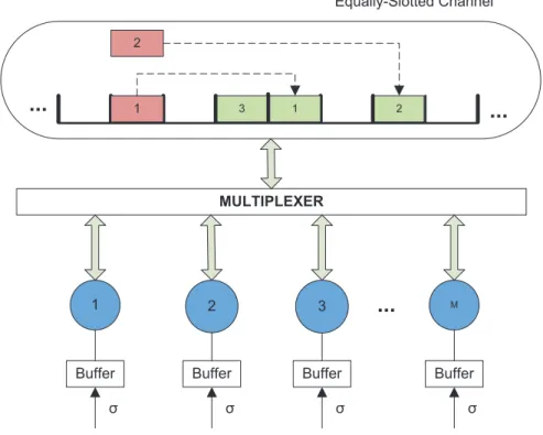
1. Communication system
(a) Synchronization: The channel is divided into equal time intervals (also
de-scribed as Equally-Slotted System). All users are aware when the slots start
and end.
(b) Fixed Network Topology: The general network topology is depicted in
Fig-ure 2.5. The multiplexer in this figFig-ure does not represent a physical device.
However, the multiplexer represents in a good way the behavior that users shall
multi-2.3. SYSTEM MODEL ASSUMPTIONS 21
plexer ”rules” are not applied by users because multiple (re)transmissions are
done by different users in the same slot, the channel will not be used efficiently.
(c) Link: It is assumed one-hop network where there are no hidden users. All users
can communicate with each other.
(d) Data Packets: All the transmitted packets in the channel are assumed to have
the same size. A data packet transmission takes exactly one time slot.
2. Transmission Channel
(a) Channel Events: There are only three possible channel events: a successful
transmission, an unsuccessful transmission and an idle slot.
i. Successful Transmission: Occurs when exactly one user transmit in a given
time slot. This event is often calledSuccess.
ii. Unsuccessful Transmission: Occurs when at least two users transmit in a
given time slot. This event is also called Collision.
iii. Idle slot: Occurs when no user transmits in a given time slot.
(b) Perfect Channel Conditions: It is assumed ideal channel conditions. This means
that the only reason why a user does not receive a packet successfully is due to
a collision.
(c) Channel Input: The channel input is a variable that represents the sum of all
new packets arriving to users’ buffers per slot.
(d) Channel Output: The channel output is a variable that represents the number
of packets successfully sent per slot.
(e) Channel Load: Defines the possible channel input amounts of traffic.
i. Saturated Traffic: A channel is said to be saturated when the channel input
is equal or greater than one packet per slot.
ii. Unsaturated Traffic: A channel is said to be unsaturated when the channel
input is less than one packet per slot.
3. Feedback Information: This is the information that the sender gets after the
trans-mission. Thus a user always knows if its unicast packets were successfully transmitted
(a) Actuality: The feedback information is available at the end of the time slot in
which the transmission takes place.
(b) Reliability: All the feedback information is error-free.
4. Users
(a) Buffer Length: Each user has an individual buffer of fixed size. Typically the
buffer can hold one packet at a time. All packets arriving to a full buffer are
discarded.
(b) Incoming Traffic: The paket inter-arrival times to users’ buffers are independent
and identically distributed (i.i.d.). For simplicity reasons, it is assumed that
the number of packets arriving to users’ queues is Bernoulli distributed in time.
This means that a user generates traffic according with σ probability.
(c) Users Operation: For each time slot a user may receive a packet, transmit a
packet or stay idle.
(d) Users State: A user is calledbacklogged when it has packets in the buffer ready
to be sent and is called a thinker if its buffer is empty.
5. Retransmissions: After a collision a packet shall be retransmitted. There are two
possible different systems: Lossless System andLossy System.
(a) Lossless System: After a collision a packet is retransmitted until it is
success-fully received.
(b) Lossy System: The packet can only be transmitted k number of times (or
in other words it can be retransmitted (k−1) times). After k unsuccessful
2.4. CLASSIFICATION OF PROTOCOLS 23
2.4
Classification of Protocols
There are various types of RMA protocols. For this reason, it is important to classify
the protocols that are analyzed in this thesis. Protocol classification can be done in
differ-ent ways, however we adopt the classification from Rom and Sidi [27]. Their Classification
is shown in Figure 2.6.
Multiple-Access Protocols
Contention Based
Contention Free
Dynamic Resolution
Static Resolution
Dynamic Allocation
Static Allocation
Time of Arrival
Probabilistic ID Reservation Token Passing
Time & Frequency
Frequency Time
Figure 2.6: Classification of multi-access protocols.
This thesis is focused in analyzing the RMA protocols in which there is no
guaran-tee that the user packet transmission will be successful. These protocols may resolve a
collision when it occurs in order to make the network more reliable by using a
retransmis-sion mechanism, so that eventually the data packets are transmitted successfully. While
solving collisions the protocol does not consume channel resources because there is not a
pre-allocation of it for any user. Even idle users do not consume channel resources either,
because they do not transmit.
The two ways of solving collisions are: Static and Dynamic resolution. The static
res-olution means that the channel dynamics does not influence the way that collisions are
handled. On the contrary, dynamic resolution relies on channel behavior in order to
re-solve the collision.
Both, static and dynamic resolution can be probabilistic. For instance in static resolution,
the transmission schedule for the users involved in the collision is chosen according with a
fixed distribution probability and it is independent of the number of users involved in the
the access probability to better adjust to the channel conditions.
The protocols on which this thesis is focused are marked with a different colour in
Fig-ure 2.6. All ALOHA protocols discussed in the next chapter (with an exception of Optimal
ALOHA) belong to Probabilistic Static Resolution with Contention group. Additionally,
all BEB protocols (and Optimal ALOHA) belong to Probabilistic Dynamic Resolution
with Contention group. The remaining protocols are contained in the category of
Con-tention Free. Here, all transmissions are successful because there is a pre-allocation of
resources. This pre-allocation can be whether Static of Dynamic. Static pre-allocation are
done by means ofTime Division Multi-Access (TDMA),Frequency Division Multi-Access
(FDMA) or a combination of both. Dynamic pre-allocation is done on demand when
a user announces the intention of transmitting and reserves the channel resources or by
passing a token between users (in which only the token holder is allowed to transmit). No
more attention will be paid to these multi-access categories since it is not the scope of the
thesis.
Due to the high number of ALOHA versions studied, correspondent classification is done
2.5. ANALYTICAL MODEL REQUIREMENTS 25
2.5
Analytical Model Requirements
The analytical model requirements of this research work are introduced in this section.
The first part of the model considered in this work is described in section 4.3.2 and it is
concluded in chapter 5. The requirements of the model considered in this work are as
follows:
1. Considers one-hop saturated network without hidden users.
2. Convergence to the previous well-known models presented in [10] and [9].
3. It is an extension of [15] and [23], by improving the finite number of (re)transmissions
capability and considering groups of heterogeneous users.
4. It uses the Regeneration Cycle Concept approach.
5. It analyzes the network throughput.
6. It allows up to G number of heterogeneous groups. Each heterogeneous group has
its own probability for accessing the channel, however inside each group, users are
homogeneous.
7. It describes BEB behavior through: the initial CW, the number of BEB states,
the maximum number of packet transmissions and the amount of broadcast traffic
generated.
8. The model shall provide the channel statistics that later on are used to extend the
model for an unequally-slotted system.
Chapter 3
Slotted ALOHA Protocol: Simple
Analysis
This chapter is dedicated to a simple analysis of Slotted ALOHA protocol. The
simple analysis means that in the analysis, a group of homogeneous users is considered.
The reasons why this protocol is being studied are shown below.
• ALOHA is the antecessor of BEB.
• The BEB evolution can be better understood when ALOHA protocol is studied in
detail.
• The ALOHA is a special case of BEB.
ALOHA is a simple protocol and it works as follows: when a user is ready for a packet
transmission, it transmits immediately the packet in the next possible time slot. Since all
users share the same radio channel, when two or more users start their transmissions at
the same time, a collision occurs such that all the collided packet transmissions cannot
be detected and decoded correctly. The channel collisions shall be handled in such a way
that the packets transmissions are scheduled for a random future time.
There are two major groups in this chapter: theGeometric ALOHA(GA) and theUniform
ALOHA(UA). In GA version users transmit according to a given transmission probability
pt. Each user generate a random numbera between 0 and 1, If pt≤a the user transmits
the packet, otherwise the user defers the packet transmission. UA is different in the sense
that it uses a fixed CW to control the channel access. Each user selects a random integer
numberW between 0 and (W0−1)1. This number W is decreased each time that an idle
time slot is sensed in the channel. WhenW reaches 0, the user transmits the packet.
Due to the amount of different versions presented in this section and to make the analysis
simpler, a list of acronyms for these GS versions is defined and explained below.
• Geometric ALOHA - Immediate Transmission (GA-IT): This version assumes that
whenever the user has a new packet, it is sent in the next possible time slot
re-gardless of pt. If a collision occurs, the packet is retransmitted in some future slot
according withpt. Hence, the immediate transmission is only true for the first packet
transmission attempt.
• Geometric ALOHA - Non-Immediate Transmission (GA-NIT): Contrarily to what
happens in GA-IT, there is no immediate transmission in this version. The packet
is always transmitted according with the user’s pt probability. Two types of system
are available with this system and both are explained later.
• Geometric ALOHA - Optimal Transmission (GA-OT): It is characterized by
adapt-ing the users’ pt to the number of backlogged users in the channel. This technique
can be applied to ALOHA versions with and without immediate transmission.
Notice that UA admits the same versions as GA. Moreover, later in this chapter GA
with Optimal Transmission is introduced and it also assumes the same set of versions as
above. Figure 3.12 shows the basic user diagram. This diagram has three states: Idle,
waiting anddata frame transmission. A user is in the idle state whenever it is a thinker
(there are no packets in the buffer), this is the state where the packet generation occurs
too. The waiting state is reached by the event E1. This event means that the user became
backlogged. Hence, in waiting state the user expects the start of the boundary slot so
that it can start the transmission. The last state is the data frame transmission and it is
reached by the event E2. This event occurs when the start of the slot is detected meaning
that the transmission can start. In state number three the user transmits the packet and
1To make matters clear CW is referred to be the Contention Window andW
0 is the initial value that
CW takes.
29
receives the feedback from the receiver. If the feedback is positive then the user returns
to state one, otherwise state 2 is reached again.
Idle Waiting
Data frame Transmission
E2 E4
E1
State 1 State 2
State 3
Events:
E1: Ready for Transmission; E2: Slot Boundary Detection; E3: Retransmission attempt; E4: Transmission Completed.
E3
Figure 3.1: Basic user sate diagram.
One shall notice that all this process is a cycle that describes the user medium access
process. More attention shall be given to ALOHA versions. Especially, in non-immediate
transmission versions there are two possible implementations. These implementations
represent the same system, however it has a different mathematical formalism. To make
matters more clear a diagram is shown in Figure 3.2. Here, it is shown where this difference
of implementations is. Basically, the difference is based on which order users generate and
transmit packets in the time slot boundary.
...
1
2
...
Users Generate New Packets
Users Channel Transmissions
Users Generate New Packets Users
Channel Transmissions
Type-1 System Type-2 System
Equally-Slotted System
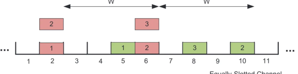
Figure 3.2: System implementation for simulation purposes.
The picture above shows what differentiates the two possible implementation versions
for simulation purposes of non-immediate transmission versions of UA and GA. In that
figure those different implementations are calledType-1 andType-2 system. Type-1
sys-tem is considered when for each beginning boundary of a slot, users generate traffic in first
of Type-1: first the transmission takes place and then users generate traffic. No matter
each type of system is considered because both of them describe the same system, however
the mathematical formalism for each one of the types is different.
In this chapter first the GA is described by means of saturated and unsaturated traffic.
Then, only saturated UA is described analytically (because of the mathematical analysis
complexity) and finally the chapters’ conclusions are made.
3.1
Geometric ALOHA
This subsection presents the GA models for saturated and unsaturated traffic. For
unsaturated traffic several models are presented: the immediate transmissions versions,
the two types of non-immediate versions and the optimal ALOHA.
3.1.1
Saturated Traffic Conditions
The saturated model is important because it represents the extreme load conditions
that a channel can experience with a given number of users. This saturated model is
usually easier to analyze mathematically because all users are backlogged thus, it is simpler
to deduce the mathematical formulas that describe the MAC behavior. The changes to
the general system assumption are:
• 2(e)i: It is assumed saturated traffic conditions.
• 4b: Users buffers’ are always full, this means σ = 1, and consequently all users
always have a packet to send.
• 5a: It is considered a lossless system. Users retransmit a given packets until it is
successfully transmitted.
All users transmit a packet in a given time slot with the samept probability and defer
the transmission with (1−pt).
Under these saturation conditions, every user has always a packet ready to be sent. A
successfully transmitted packet in the channel is observed when exactly 1 of M users
3.1. GEOMETRIC ALOHA 31
Sout=
M 1
pt(1−pt)M−1=M pt(1−pt)M−1. (3.1)
In equation (3.1)3,pt represents the probability in which the successful user transmits
and (1−pt)M−1 are the remaining users that do not transmit.
Since only one packet can be successfully sent in each time slot, equation (3.1) can also
be interpreted as the system departure (Sout) in a time slot. To maximize the system
departure, it is needed to find the maximum of the equationSoutlike is shown below.
∂Sout ∂pt
= 0↔M(pt ∂ ∂pt
(1−pt)M−1+ (1−pt)M−1) = 0↔
↔M(1−pt)M−1[1−(M −1)pt(1−pt)−1] = 0↔pt = 1∨pt =
1
M. (3.2)
The probability that maximizes the system departure (poptt ) under saturation
condi-tions is M1. The other solution of the equation (3.2) does not make sense because if all
users transmit with probability one (pt= 1) in each time slot under saturation conditions,
they would collide in every transmission attempt.
The maximum possible system departure (Smax
sat ) is given by replacing the optimum
trans-mission probabilitypoptt in (3.1), for an infinite channel input (M → ∞).
Ssatmax= lim
M→∞Sout(p
opt
t ) = limM→∞(1−
1 M)
M−1 = 1
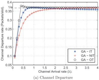
e ∼= 0.36. (3.3)
Equation (3.3) proves that the maximum possible system departure for an infinite
arrival rate in probabilistic slotted Aloha is ∼= 36%. One might notice that Smax
sat can
only be archived when all users use the same optimum transmission probabilitypoptt under
saturation conditions.
3.1.2
Non-Saturated Traffic Conditions
In this section, different GA models for unsaturated traffic are presented. These
models describe the system departure, delay and stability analysis. The unsaturated
3It is worth to mention that
M 1
channel traffic condition is important because it is the most common traffic condition
in networks. In this subsection, the Geometric ALOHA with Immediate Transmission
(GA-IT),Geometric ALOHA non-Immediate transmission(GA-NIT) and theGeometrical
ALOHA - Optimal Transmission (GA-OT) are described. In GA-NIT, the Type-1 and
Type-2 systems are compared in order to make it clear that both versions describe the
same system. The changes to the general system assumption are:
• 2(e)ii: It is assumed unsaturated traffic conditions. The traffic generation is assumed
to be Bernoulli distributed with σ probability.
• 5a: It is considered a lossless system. Users retransmit a given packets until it is
successfully transmitted.
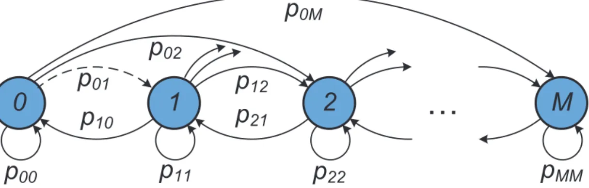
A general Markovian model is formulated based on Kleinrock research [7], for a
net-work with a population ofM users. The number of users in the network is considered to
be large and finite.
0
1
2
…
M
p
00
p
11
p
22
p
MM
p
10
p
21
p
12
p
02
p
0M
p
01
Figure 3.3: Generic Markov chain for ALOHA protocol.
The states in the Markov chain depicted in Figure 3.3 represent number of network
backlogged users. There is M + 1 chain states representing the 0,1,2, . . . , M possible
backlogged users. Each version of the GA has its own transition probability matrix.
The dashed arrow in the general Markov chain is only meant to be considered the GA
versions without immediate transmission. Moreover, in the GA-IT it is not possible to
make the transition from state 0 to state 1 because only one user can transmit successfully
in a given time slot. This means that whether only one user transmits successfully and
3.1. GEOMETRIC ALOHA 33
network suffers ak chain forward hop transmission. Note that this property also explains
the first equation of all Markov Chains system equations of all GA versions explained later
on in this chapter.
All presented versions of GA assume a fixed one size buffer. Like it is explained in [26],
these models rely on multiple access channels with large number of users, small arrival rate
λ and consequently small delay. With these assumptions, the new arrivals to backlogged
users are almost negligible. Thus, this one size buffer assumption provides a lower bound
on the delay and system departure. Moreover, it makes the model easier to analyze because
only 1-D Markov chain is needed.
Geometric ALOHA - Immediate Transmission (GA-IT)
Here, the GA-IT mathematical model is presented. Notice that in this version of GA,
the dashed arrow of Figure 3.3 is not considered due to the immediate transmission feature.
AssumingM as the total number of users and Nt as the number of backlogged users at
timet, the channel input at timetisSt = (M−Nt)σ. Once that a user can only be either
a thinker of a backlogged, the difference M −Nt represents the number of thinker users
in the network, the ones whose actually can generate new packets. The transition matrix
that represents the GA-IT version is shown bellow, where i and j represents the state
number (or number of backlogged users) 0,1,2, . . . , M at different discrete time instants.
pi,j = Pr{N(t+1)=j|N(t)=i}= (3.4)
=
0, if j≤i−2,
ipt(1−pt)i−1(1−σ)M−i, if j=i−1,
(1−pt)i(M −i)σ(1−σ)M−i−1+
+[1−ipt(1−pt)i−1](1−σ)M−i, if j=i,
(M −i)σ(1−σ)M−i−1[1−(1−p
t)i], if j=i+ 1,
M −i
j−i
σj−i(1−σ)M−j, if j≥i+ 2. .