Dissertation
Master in сivil engineering
Calculation and comparison of steel structures of public
building considering the seismic loads according to the
Ukraine Norms
Zhmykhova Veronika
Dissertation
Master in сivil engineering
Calculation and comparison of steel structures of public
building considering the seismic loads according to the
Ukraine Norms
Zhmykhova Veronika
Dissertation developed under the supervision of professor Hugo Filipe Pinheiro Rodrigues, adjunct professor at Departament of Civil engineering of the Polytechnic Institute of Leiria and co-supervision of professor Sergiy Kolesnichenko , professor at the Donbas National Academy of Civil Engineering and Architecture .
iii
Resumo
De acordo com os códigos de construção da Ucrânia B.1.1-12-2014 "Construção em regiões sísmicas da Ucrânia" [1] um edifício na Ucrânia pode sofrer os efeitos de ações sismicas. Áreas com maior perigosidade estão localizadas na Ucrânia Ocidental, a região de Odessa e a Crimeia. Mapas de zoneamento sísmico geral, mostram que uma vez em 1000 anos com uma probabilidade de 10%, quase metade do território da Ucrânia pode ser submetido a um terremoto.
Atualmente, na concepção de edifícios e cálculo de estruturas fora das áreas da atividade sísmica mais perigosa geralmente não é considerado efeitos sísmicos. Em cargas sísmicas são calculadas apenas a construção de grau V.
A relevância deste tópico: A probabilidade de ocorrendia de eventos sísmicos na Ucrânica que podellivar à destruição, perda de ativos e perdes de vidas humanas.
Caso de estudo: Estudar o grau de influência da ação sísmica na estrutura do edifício, dependendo da ação considerada.
Métodos de cálculo e análise:
- método dos elementos finitos, implementado no complexo de software SCAD;
- Análise do estado de tensão-deformação dos elementos estruturais e comparação dos mesmos com o máximo admissível.
Novidade científica. Determinação do impacto da carga sísmica no esforços e nos deslocamentos da estrutura metálica do edifício por modelação numérica de diferentes intensidades sísmicas. Palavras-chave: ação sísmicas, modelo de cálculo, deslocamento, deformação, carga sísmica, modelação numérica, Ucrânia.
iv
Abstract
According to State Building Codes B.1.1-12-2014 "Construction in seismic regions of Ukraine" a building in Ukraine may be prone to seismic effects. Especially dangerous areas are the Western Ukraine, Odessa region and Crimea. Maps of general seismic zoning (GSZ), show that once in 1000 with a probability of 10%, almost half the territory of Ukraine may be subjected to an earthquake measuring at least 6 points.
Currently in the design of buildings and calculation of structures outside the areas of the most prone seismic activity is usually not to considered seismic effects. The seismic loads are calculated only building V grade.
The relevance of this topic: - The propability of earthquakes in Ukraine may lead to destruction and losses of assets and fatalities.
Subject of study. The degree of influence of seismic loading on the structure of the building, depending on the intensity of the earthquake.
Methods of calculation and analysis:
- finite element method, implemented in software complex SCAD;
- Analysis of the stress-strain state of structural elements and comparing them with the maximum permissible.
Scientific novelty. Determining the impact of seismic loading on stress and displacement in the steel frame of the building by numerical modeling at different intensity earthquake.
Keywords : seismic loads, calculation model, displacement, strain, seismic loading, seismic activity, stiffness, numerical modeling, Ukraine.
v
List of figures
Fig. 2.1. The new seismic zoning map of Ukraine for 1000 years return period repeat
Fig.2.2. Example building design complex shapes in seismic areas. Fig.2.3.1. Basic concepts of seismology.
Fig. 2.3.2: longitudinal waves (compression or dilation). Fig. 2.3.3:Shear wave (shear wave).
Fig. 2.3.4: Love surface waves. Fig. 2.3.5: Surface Rayleigh waves.
Fig. 2.3.6. Akselerohrama, velosyhrama, seismograms. Fig. 3.1. Payment schemes buildings:
a - as multimass console rod, b - in the form of cross multimass system, c - as a spatial dynamic model.
Fig.4.1. Sectional building model Fig.4.2. Design model plan
Fig.4.3. Diagram public buildings
Fig. 5.1.1. Selected columns for analysis Fig. 5.1.2. Selected main beam analysis
Fig. 6.2.3. Examples of systems energy-absorbing elastic-friction connections (a). Plastic energy-absorbing in communication systems steel frames (b).
Fig.8.1. Location of additional bonds in the background. Fig.8.2. Location of bonds in the transverse direction. Fig.8.3. Location of bonds in the longitudinal direction. Fig. 6.1. Seismic protection classification methods.
Fig.6.2.1. Example of Adaptive seismic isolation 1 - bearing risers, 2- coherent panel.
vi
Fig.6.2.3. Examples of systems energy-absorbing elastic-friction connections (a). Plastic energy-absorbing in communication systems steel frames (b).
Fig.8.1. Location of additional bonds in the background. Fig.8.2. Location of bonds in the transverse direction. Fig.8.3. Location of bonds in the longitudinal direction.
vii
List of tables
Table 2.4.1 - MSK-64
Table 4.1 - The coefficients for the combination of static loads. Table 4.2 - Values of coefficients for the seismic load combinations. Table 5.1.1. Table of stresses and displacements from static loads. Table 5.2.1 Table angles to cosines and their application of seismic loading.
Table 5.2.2. Comparison of static and seismic load in 5 points for selected elements.
Table 5.3.1. Comparison of static and seismic load in 6 points for selected elements.
Table 5.4.1. Comparison of static and seismic load in 7 points for selected elements.
Table 6.4.1. Comparison of seismic load in 6 points for a building with normal sections and buildings with sections increased by 20%.
Table 6.5.1. Comparison of stress and displacement values for normal and building buildings with additional structural elements .
viii CONTENT Resumo………..…………..…….……3 Abstract……….……….………….….4 List of figures……….……….……….… ……..5 List of tables……….……….… …...…..7 Chapter 1………..…………...……10 1.1 Introduction……….………….…...…10 1.2 Objectives on Motivation ……….……….10
1.3 Organization of the document ……….……..11
Chapter 2 The general state of the problem………….……...13
2.1 Introduction………..…….13
2.2 Basic requirements for the consruction in seismic areas ….14 2.3 Basic concepts of earthquake ……….20
2.4 Crading scale earthquake ……….24
2.5 Seismocity different regions of Ukraine ………28
2.6 Maps zoning of Ukraine ………..31
Chapter 3 Methods based on seismic loads………..39
3.1 Spectral method of calculation ………..40
Chapter 4 Program and methodology of experimental studies of numerous changes of stresses and displacements in the metal frame of seismic loads………..44
4.1 Methods of analysis of the calculation results ………..46
4.2 Initial data studied building ………47
Chapter 5 Study changes in stress es and displacements metal frame of the building from seismic loadind at 5,6,7 points ………51
5.1 Calculation and analysis of stresses and displacements in the metal frame of the building static loads ………58
5.2 Calculation and analysis of stresses and displacements in the metal frame of the building from seismic load intensity of 5 points……….74
ix
5.3 Calculation and analysis of stresses and displacements in the metal frame of the bui lding from seismic load intensity of 6 points………..79 5.4 Calculation and analysis of stresses and displacements in the
metal frame of the building from seismic load intensity of 7 points………..85 6. Methods seismic protection. General features methods ……86 6.1 Traditional methods provide earthquake resistance ……….86 6.2 Special seismic protection ………88 6.3 Strengthening the building frame sections basic way to increase
the load-bearing structures………91 6.4 Boost frame building means the installation of additional
structural elements ……….96 7. Recommendations for the design of the results of the
calculation………..104 8. General conclusions on research ………..106 References……….107
1
Chapter 1
Introduction
1.1 - Introduction
Portugal is located in an active seismic zone. The quake there can be up to eight points or more. On average earthquake happens 1 time in 2 years. The most devastating and deadly earthquake struck Oct. 1, 1755, while Lisbon - Portuguese capital, has turned into ruins. The strength of this earthquake according to data of geologists was about 8.7 magnitude. This event was starting to the birth of modern seismology [19].
According to State Building Codes B.1.1-12-2014 "Construction in seismic regions of Ukraine" [1] building in Ukraine may be prone to seismic effects. Especially dangerous areas are the Western Ukraine, Odessa region and Crimea. Maps of general seismic zoning (GSZ), show that once in 1000 with a probability of 10%, almost half the territory of Ukraine may be subjected to an earthquake measuring at least 6 points. According Ukrgeology earthquakes seismicity of these areas can grow two or more times.
Currently in the design of buildings and calculation of structures outside the areas of the most dangerou s seismic activity is
2
usually not considered seismic effects. In seismic loads are calculated only building V grade.
The relevance of this topic - the likelihood of earthquakes on the MSK-64 6 - points or more in most parts of Ukraine. Not account such important factors may lead to destruction of, loss of assets and the worst - death.
1.2 – Objectives and Motivation
The main objective of the present study is to a nalyze the impact of seismic loads in tension and moving elements in the frame of the building in the area of seismic activity , namely by:
- Examine the existing methods based on seismic loads;
- Evaluate the effect on a a public building design model in the software sector SCAD;
- Apply to the calculation model is static, seismic activity and perform the calculation;
- Determine the change of stresses and displacements in the elements of the building from seismic load;
- Perform amplification by increasing the frame sections bearing structures;
- Perform amplification by introducing a new constructive scheme yelementiv frame;
- Analyze the results and to recommend their choice of design and technical solutions frame building.
1.3 Organization of the Document
The present work was organized in seven chapters. The present chapter introduces and explain the motivation for the work that has been developed.
3
Chapter 2 presents a review of the literature, which describes earthquakes in Ukraine, provides recommendations for designing for territories with seismic activity, and seismic measures that are applied in the territory of Ukraine.
Chapter 3 discusses methods for calculating buildings for seismic loads.
Chapter 4 presents a case study of a fourteen -story metal frame, designed in accordance with the building codes of Ukraine for construction in an inactive se ismic zone. The methodology of developing an experimental model and analyzing the results is described.
In Chapter 5, considering the seismic design rules, the values of stresses and displacements under seismic load of intensity 5.6 and 7 points were obtained experimentally.
In Chapter 6, with the use of traditional methods, namely, increases in the cross -sections of load-bearing elements and the establishment of additional structural elements, the values of stresses and displacements for the same ballistics were also calculated.
In Chapter 7, based on the data of the foregoing sections, conclusions were drawn about the effectiveness of seismic protection methods and recommendations for design were given. The main conclusions and future work are pre sented.
4
CHAPTER 2
STATE OF THE
PROBLEM
2.1 Introduction
In Ukraine the calculation, construction, reconstruction and overhaul of reinforced concrete, metal, stone, wood structures of buildings and structures erected or placed in areas with seismicity 6 points or higher on a scale of seismic intensity according to ISO B . 1.1-28: 2010 [20], to protect against the negative impact of seismic events on the safety of people and the preservation of material and cultural values carried out accordin g to the requirements of State Building Code B.1.1-12: 2014 [1].
The International Geophysical Journal №3 2006 published an article "New maps of general seismic zoning of Ukraine. Model features long seismic hazard [19]. " According to this study, the probability of an earthquake and its power as a result of technological activities may increase by 2 points (Fig. 2.1). So the higher hazard zones in Ukraine are the Crimea and Odessa region.
5
Fig. 2.1. The new seismic zoning map of Ukraine for 1000 years return period repeat.
2.2 Basic requirements for construction in seismic areas.
Basic requirements for construction in seismic areas are reduced to taking the following measures [1]:
1. The choice of sites for construction.
2. Select a constructive solution (CR) and space -planning decisions (ODA).
3. Ensuring high quality construction.
4. Separation buildings antiseismic seams. Building sites for settlements and structures are selected on th e basis of geological
6
data, away from potential or apparent faults, away from steep slopes, threatening landslides and landslides. Unfavorable for building considered loose soils and fractured rock.
When choosing a site for development into account such things as seismic construction projects and seismicity of the construction site.
The ability of soils, buildings and structures to resist seismic called seismic. Measures to improve the earthquake res istance of buildings used in areas with seismicity of 7 points or higher. Normative justification for these measures carried out by State Building Code (SBC) C B.1.1-12: 2014. "Construction in seismic regions of Ukraine." For more seismic 9 points of capit al construction of buildings is prohibited.
Seismicity construction site depends on the seismicity of the area and seismic soil, which are ground and are divided into categories. Seismic intensity construction site is determined based on the results of the seismic zoning (SZ), which is performed for areas with seismicity 6 points or more. In the absence of seismic zoning maps may be simplified definition seismic construction site on the basis of geological surveys.
When designing buildings usually take regu latory seismicity of the construction site, which corresponds to the second category. For soil category 1 settlement seismicity decreased by 1 point, and for soils 3rd category - increased by 1 point compared to normative. We know that buildings are constructed in seismically dangerous areas, are designed to meet the various criteria for the conduct of various intensity earthquakes.
7
When designing earthquake -resistant buildings adhere to the following principles:
1. The principle of symmetry, rigidity and weight should be distributed evenly and symmetrically about the plane of symmetry passing through the center of gravity of the building. That building project in terms of simple shape and symmetrical (circle, square, rectangle). Buildings complex shape in plan is divided into compartments simple form seismic seams in a pair of walls (wall of buildings) or the even frames (in frame buildings).
2. The principle of harmony, proportionality must be observed in the size of the building, with its length or height should not be very large. Limit the size, number of floors, the height of floors of buildings taken according to SBC B.1.1-12: 2014.
3. The principle anesthetic: to design the building as easier, with the center of gravity located low as possible.
4. The principle of elasticity of materials used in the construction of desirable durable, lightweight, having elastic properties; the design of which should have homogeneous properties.
5. Providing closed loop: load -bearing structural elements to be interconnected to form a closed loop both vertically and horizontally.
6. Ensuring reliability of foundations, structures for earthquake -resistant foundation should be strong enough deeply laid, preferably in layers of pliable or special substruktsiyah substitute w eak soils, to ensure consistency and strength of soil base. Belt teams lay the
8
foundations for one mark and make continuous. Pile foundation raft made low, buried in the ground. We recommend using a solid slab foundation. Basement is located under the whol e compartment. In frame buildings Column footings interconnecting continuous reinforced concrete foundation beams in the form of cross belts.
Fig.2.2. Example building design complex shapes in seismic areas.
7. Use seismic isolation : advisable to use dev ices that reduce the intensity of oscillatory processes transmitted from the ground to the building. During the construction of dams and bridges reinforce their base, arrange more gentle slopes. New construction buildings increase the cost of construction, but it eventually pays off, saving the lives of many people, saves from destruction expensive industrial facilities.
Buildings and facilities should be separated seismic seams in cases where:
building or structure has a complex shape in plan;
areas adjacent building or structure with elevation of 5 m or more. In single-storey buildings up to 10 m in settlement seismicity
9
of 7 points anti-seismic joints are allowed to organize. Seismic joints have to share buildings and structures across the top. Pets not arrange joint in the basement, except when aseismic seam coincides with sedimentary. Stairwells should include closed, such as with external walls window openings. The location and number of staircases should be determined by the calculation performed according to the requirements of SBC B.1.1-7-2016 "Protection against fires. Fire safety of buildings and structures “but take at least one staircase seismic seams between tall buildings over three storeys. Seismic joints should be performed by bringing t he pair of walls or frames,
The strength of building materials seismic loads.
The strength of building materials and structures depends not only on the physical properties but is largely determined by the conditions in which they are operating under stress . In terms of earthquake strength characteristics of the material, of course, determined the seismic characteristics of the load. One of these features characteristic of any earthquake is the brevity of the load, that is a small number of cycles of its rep etition. Another factor which is important for building structures and materials, is the frequency of the load. As shown by numerous experimental studies, structures vary with the frequency corresponding to the frequency of natural oscillations, regardless of the frequency of external influence. Same period of free oscillations of most buildings is about 0.1 ... 2.0 s, and, therefore, the frequency of dynamic loads affecting the building in terms of earthquakes be located primarily within 0.5 ... 10 Hz. Con sidering the carrying capacity of structures and materials, keep in mind that a strong earthquake - a phenomenon
10
relatively rare, so ensuring the operational usefulness of objects after the earthquake may be uneconomical since the service life of these buildings may be less than the recurrence period of strong earthquakes. Therefore, in earthquake engineering is not a requirement to ensure the full preservation and suitability for further operation of buildings that have undergone seismic loads; most importantly - to ensure the safety of people and the preservation of the most valuable property. Considering the carrying capacity of structures and materials, keep in mind that a strong earthquake - a phenomenon relatively rare, so e nsuring the operational usefulness of objects after the earthquake may be uneconomical since the service life of these buildings may be less than the recurrence period of strong earthquakes. Therefore, in earthquake engineering is not a requirement to ensure the full preservation and suitability for further operation of buildings that have undergone seismic loads; most importantly - to ensure the safety of people and the preservation of the most valuable property. Considering the carrying capacity of structures and materials, keep in mind that a strong earthquake - a phenomenon relatively rare, so ensuring the operational usefulness of objects after the earthquake may be uneconomical since the service life of these buildings may be less than the recurrence period of strong earthquakes. Therefore, in earthquake engineering is not a requirement to ensure the full preservation and suitability for further operation of buildings that have undergone seismic loads; most importantly - to ensure the safety of people and the preservation of the m ost valuable property. since the lifespan of such buildings may be less than the recurrence period of strong earthquakes. Therefore, in earthquake engineering is not a requirement to ensure the full preservation and suitability
11
for further operation of bui ldings that have undergone seismic loads; most importantly - to ensure the safety of people and the preservation of the most valuable property. since the lifespan of such buildings may be less than the recurrence period of strong earthquakes. Therefore, in earthquake engineering is not a requirement to ensure the full preservation and suitability for further operation of buildings that have undergone seismic loads; most importantly - to ensure the safety of people and the preservation of the most valuable p roperty.
2.3 Basic concepts of earthquake engineering
Earthquake are oscillatory motion of the upper layers of soil strata. Earthquakes usually occur in zones of faults where tectonic processes are most active, and the strength of the crust is reduced. Seismic vibrations may also have other causes: explosions, rock bursts in underground mines, volcanic activity, traffic, etc. But such fluctuations are weaker and more usually felt only a short distance from the source of origin.
Deep land area covered by seismic dislocations, called a fire or earthquake hipotsentralnoy area and focus the projection to the surface of the Earth - epitsentralnoy area. Central point of this area is called the epicenter and the distance from it to the object - epicenter distance (Fig. 2.3.1).
The biggest strength of the earthquake is usually epitsentralnoy area. As the distance from the power of the earthquake it falls. Lines of equal strength earthquake that separate the different areas balnosti called Isoseists (Fig. 2.3.1).
12
In appearance form isoseists affect focus, topography, soil conditions, and some other factors.
From earthquake to surface apply two types of seismic waves, called deep, longitudinal and transverse.
The longitudinal waves (compression or dilation) define compression - stretching soil volume element (Fig. 2.3.1). Particles in this range in the direction of wave propagation.
Shear wave (shear wave) shear strain determining the basic amount of soil (Fig. 2.3.3). Soil particles range in this perpendicular direction of wave propagation.
Fig.2.3.1. Basic concepts of seismology.
13
Rayleigh surface waves and Love. Rayleigh waves similar to waves on the surface, v. E. The particles are displaced perpendicular to the surface (Fig. 2.4), and Love waves shift occurs in t he plane of the earth's surface.
Fig.
2.3.2: longitudinal waves (compression or dilation).
Fig. 2.3.4: Love surface waves.
Fig. 2.3.5: Surface Rayleigh waves.
Velocity of deep waves depends on the density of the medium and its elastic properties. Shear waves propagate approximately 1.5 Fig. 2.3.3:Shear wave (shear wave).
14
times slower longitudinal. Even less velocity of propagation of surface waves.
Therefore, during the earthquake exposed structur es consistently longitudinal, transverse and surface waves.
Length of seismic waves and, therefore, the period seismic waves depend on the seismic fault. Since the rupture of the crust cracks appears a large number of different sizes and each of them at the time of its formation emits waves of the earthquake is characterized by a wide range of oscillations with a period of ten seconds to a few hundredths of a second.
Fluctuations in soil mass points during earthquakes are characterized seysmohramu, velosyh ramy and akselerohramamy, representing a schedule change under displacement, velocity and acceleration discussed points in time ( Fig.2.3.6) [2].
15
2.4 Grading scale earthquake
The degree of the impact of the earthquake on the objects reflected seismic scale scores depending on the degree of destruction of standard buildings, witness’s sensations, changes in the earth's surface.
The intensity of the earthquake on the surface mani festation measured in points, depending on the depth of focus and magnitude earthquake, which is a measure of its energy. The maximum value of a certain magnitude approaching nine. The magnitude of total energy associated with earthquakes, but this relatio nship is not direct, but logarithmic, with increasing magnitude per unit of energy increases by 32 times, ie when the shock of magnitude 6 is released 32 times more energy than a magnitude 5 and nearly 1,000 times greater than a magnitude four. The intensi ty is greater the closer to the center of the surface is, for example, if the earthquake with a magnitude equal to 8, at a depth of 10 km, the intensity of the surface will be 11-12 points, with the same magnitude, but at a depth of 40 - 50 km impact on the surface is reduced to 9.10 points.
Developed several scales to determine the intensity of earthquakes. The first one was proposed in the 1883 -1884 biennium. M. and F. Rossi trout, according to the intensity of this scale was measured in the range of 1 to 10 points. Later, in 1902, the US ha s developed a more advanced 12 -point scale, known Mercalli Intensity Scale (named after the Italian volcanologist). This scale, modified, and now widely used by seismologists US and other countries. In our country and some European countries use 12 -point international scale of earthquake intensity (MSK -64), known as the first letters of the authors (Medvedev -Shponhoyera-Karnyka).
16
The duration of earthquakes is different, often creates a number of aftershocks swarm of earthquakes, including previous (Foreshock) and following (aftershock) shocks. Distribution of the strongest push (main earthquake) within the swarm is random. The magnitude of the strongest aftershock of 1.2 fewer than the main shock, aftershock those involving its secondary series of aftershocks.
All these scales have two parts: macroseismic (descriptive) and instrumental. The first sets of earthquake intensity based on subjective evaluations, the second - the quantitative characteristics of seismic ground motions obtained by instrumental recor ds.
Table 2.4.1 - MSK-64 [21]
Mark Criteria
One Point Men do not feel an earthquake, except for isolated observers who are particularly sensitive places and in high position. The tremors are recorded only
specialized seismographs.
Two Points The earthquake is very weak. Fluctuations in soil felt few people who are alone, especially in the
uppermost floors of the buildings located in the vicinity of the epicenter.
Three Points Earthquake weak. Vibrations are felt in areas, mainly in the upper floors of tall buildings. During the
earthquake swing hanging objects, especially chandeliers, creaking and begin to move the door dissolved. Those cars is starting to wobble slightly
17
on springs. Some people are able to estimate the duration of the shock.
Four Points Moderate earthquake. It is felt by many people,
especially those who are in the room. Few people can feel an earthquake outdoors, and only those who currently is at rest. Some people on the night of the wake of the earthquake. At the time of the
earthquake swing hanging objects, rattles windows, clap doors, ringing utensils, cracking wooden walls, cornices and ceilings. Visibly swaying on springs are cars.
Five Points Tangible earthquake. It is felt by all people,
wherever they are. Wake all sleeping. Doors swing open on hinges and spontaneously, banging shutters, closed and open windows. The liquid in the vessels swings and sometimes overflow. Beats of dishes, cracked glass, sometimes in plaster cracks, thrown furniture. Pendulum clocks stop. Sometimes swaying telegraph poles, supporting poles, trees are tall
objects.
Six Points A strong earthquake. It is felt by all people. Many people fear leaving the room. At the time of gro und motion and after gait becomes unstable. Beat
windows and glassware. Some objects fall from the table. Fall picture. Begins to move and thrown
furniture. There are cracks on the walls in masonry. Visibly shaking trees and bushes.
18
instinctive fear of running out of space. Tremble suspended objects. Broken furniture. Many homes received severe damage. Chimneys break off at roofs. Plaster falls off badly stacked bricks, stones, tiles, cornices and parapets specifically unfortified. There are large cracks in the soil. The ongoing landslides and rock falls on stony and clay slopes. Involuntary bells are ringing. The rivers and open water mutniye water. Water splashed out of the pool. Crumbling concrete irrigation canals.
Eight Points The devastating earthquake. Typical buildings receive significant damage. Sometimes partially destroyed. Old buildings are destroyed. There is a panel of lead frames. Swaying and falling furnace and factory chimneys , monuments, towers, columns, water towers. Broken pile. Break off branches of trees, there are cracks in the wet ground and on steep slopes.
Nine Points The devastating earthquake. From the action of the earthquake there is panic. Buildings are destroyed . Seriously damaged dam and reservoir board. Torn underground pipelines. At the Earth's surface there are significant cracks.
Ten Points Destroys earthquake. Most of the buildings
crumbling to the ground. Afflict some well -built wooden structures and bridges. Serious damage to get the dams, embankments and dams. At the Earth's surface there are numerous cracks, some of which
19
have a width of about 1 m. There are large gaps and large landslides. Water pouring out of the channels, riverbeds and lakes. Begin to move sand and clay soils on beaches and low-lying areas. Slightly bend rails for railways. Break large branches and trunks of trees.
Eleven Points
The catastrophic earthquake. There are still only a few particularly strong stone buildings. Crumbling dams, embankments and bridges. On the ground there are wide cracks that go deep into the subsoil.
Underground pipelines completely breaking d own. Strongly bubbled rails for railways. On the slopes there are large shifts.
Twelve Points
Strong catastrophic earthquake. Complete destruction of buildings. By drastically changing the landscape shifted rocky areas, zsuvatysya slopes, there are large gaps. Earth's surface is wavy. Formed
waterfalls, new lakes, rivers change. Vegetation and animals are killed by landslides and scree. The debris of stones and objects vzmetayutsya high into the air.
2.5 Seismicity on Ukraine regions
In Ukraine, the force of shocks and vibrations during earthquake made to measure 12-point scale of intensity. Also often
20
used magnitude (strength earthquake the Richter scale). Because its seismographs record an d intensity determined by the force of destruction.
Significantseismic there are processes in western Ukraine, including transcarpathia where once were earthquake sintensity of 6-7 points. Epicentersthese earthquakes were in the area Long, Teresva, Mukachevo, Uzhgorod. Earthquake Oct. 15 1834. (7 points) covered a large area of Transcarpathia (Svalyava about to Rakhov).
In the central part of Western Ukraine earthquake intensity of 6 points in the epicenter were record ed in Kamenka-Bugand Zalischyky. With in Chernivtsi region one earthquake recorded intensity 5 points.
South of Ternopil, Khmelnitsky, Vinnytsia and Odessa regions okonturyuyut isoseists intensity of 6 points. Isoseists to 5 extends north up to the line Berestechko-Rivne-Kiev-Pereyaslav-Khmelnitsky-Dnipropetrovsk. In the extreme south of Ternopil, Khmelnytsky, Vinnytsia and Odessa regions in the west are Isoseists intensity of 7 points. And these earthquakes occur here many times. Most earthquakes are associated with tectonic movementsin the mountains Vrancea (On the border of South and East Carpathiansin Romania).
For Crimea also characterized by intense (5 -6 points) seismic activity. Crimean earthquake epicenters are usually located mainly in Black sea (Mainly between Alushta and Foros). For example, the earthquake Isoseists to 5 held November, 11th 1927, reached the extreme northern part of the peninsula; Isoseists earthquake of the same intensity to 8 points most of oko nturyly Crimean mountains.
21
Thus, a large area of southwestern and southern Ukraine belongs to the seismically unsafe. This fact must always be considered when justifying the placement of new construction.
Ukraine has a national network of seismic studies comprising 18 seismic and 14 integrated geophysical stations. The oldest is a seismic station "Lviv" Which is based 1899 year. Digital seismic station "Kiev" organized 1994, and is part of the Global Seismic Network.
For engineering and seismic assessments, an increa se of seismicity in southern Ukraine than 1.5 points, and therefore it was determined that in some areas 30 -50% area does not meet the current level of seismic risk and engineering.
In Donbass crust has a large enough capacity that is protection against earthquakes. At the beginning of the XX century recorded, weak seismic manifestations in Lisichansk and other places that did not cause significant damage. But in the Donbass well known dangerous manifestations of sudden coal and gas mining, rock bursts and other geodynamic phenomena. Periodic increase tectonic stresses caused by earthquakes, in conjunction with mining activity leads to disastrous consequences.
August 7, 2016 was occurred in the Donetsk region earthquake a magnitude of 4.6 points. The epicenter of the earthquake was located 78 km south of Donetsk and 21 km north of the town. Old Crimea Mariupol region, epicenter depth - 10 km.
As you can see, the threat of earthquakes is increasing every year, so even this seeming ly quiet place on the planet as Ukraine, should be prepared for disasters. Most of the country is in a safe area, magnitude 4.5 earthquakes can not cause substantial damage or
22
buildings or people. But it is necessary to consider the fact that the building and construction in Ukraine do not provide tremors, so more prone to mechanical damage due to possible earthquakes.
2.6 Maps zoning of Ukraine
There are seismic zoning map s (Fig. 2.6.1.), That bear the same areas with the expected intensity of earthquakes. For such cards in Ukraine are in standards [1]. It should, however, bear in mind that these cards give the average ( "background") intensity values, while devastating earthquake heavily dependent on the characteristics of the geological structure and soil conditions specific construction site. Therefore, when choosing sites for critical facilities, including nuclear power, carried out extensive geological and seismological research ("mikroseysmodivided ") to determine the real seismi c risk. [1]
Maps of general seismic zoning (GSZ) in Ukraine with insert cards of the Autonomous Republic of Crimea and Odessa region with periods of recurrence once in 500 years (map A), 1000 (map B) and 5000 years (Map C) for medium soil conditions and probability exceeding the estimated intensity for 50 years, 10%, 5% and 1% respectively.
SRF Insert cards in AR Crimea and Odessa area, in addition to card A, B, C, supplemented by maps A0 for the average recurrence period of 100 years the probability of exceeding a given intensity 39% over 50 years [1].
29
30
Chapter 3
Methods based on
seismic loads
3.1. Introduction
Calculation of structures and foundations of buildings and structures for construction in seismic areas should be carried out on the basic and special combination of loads based seismic action. In a special combination of loads include permanent, possible long -term and short-term loads, seismic actions and actions that caused deformities basis for soaking soil subsidence.
Calculations structures on the special combination of loads based seismic actions shall be implemented using:
a) spectral method - should be carried out for all buildings. This method is sufficient for works of simple geometric shapes symmetrical and regular deployment of mass and stiffness of the smallest size in terms of no more than 30 m;
b) direct dynamic method - using instrumental records acceleration of ground during earthquakes or standard set of synthesized accelerograms - for works particularly critical height of over 50 meters (over 16 floors) and structures with spans more than 30 meters or a fundamentally new design solution. In these calculations should consider the possibility of inelastic deformation structures. Seismic actions can have any direction directions in space. The maximum amplitude of acceleration grounds foundation, foundation should be taken at least 100, 200 or 400 cm/ s2 at seismic
31
construction sites 7, 8 and 9 points respectively. For buildings of simple geometric shapes estimated seismic load should be taken such that the horizontal force in the direction of longitudinal and transverse axes.
When calculating the structures of complex geometric sh apes should be considered the most dangerous for the design or its elements directly sending seismic action. The vertical component of the seismic action must be considered in the calculation:
- console horizontal and inclined structures; - span bridge structures;
- frames, arches, trusses, spatial coverages buildings span of 12 ... 24 meters or more, depending on the seismicity of the area;
buildings, structures and foundations for stability against overturning or slip;
- high pile structures raft;
- strength load-bearing walls of masonry; - seismic isolation support elements.
3.2. Spectral method of calculation.
In determining the design values of horizontal seismic loads on buildings height H exceeding two or more times its width B and length L is allowed to make d esign scheme (Fig. 3.1, a) as multimass elastically deformed cantilever rod firmly fixed on basis, which is concentrated mass weight Qk, located on level floors, and makes vibrate in one of the directions (x or y). With the width of the building in which t hree or more times less than two of its other dimensions (H and L), allowed to make design scheme (Fig. 3.1, b) as multimass elastic-deformed cross-system with concentrated at
32
nodes masses located on level floors. Typically, the recommended settlement spatial dynamic models with lumped masses at the nodes (Fig. 3.1, c).
Fig. 3.1. Constructive schemes buildings:
a - as multimass console rod, b - in the form of cross multimass system, c - as a spatial dynamic model.
Estimated value of horizontal seismic load Ski, applied to the point and meets k i -th form of natural vibrations of a building or structure shall be determined by the formula:
ki ki k k k S
S 1 2 3 0
where k1 -factor considering inelastic deformation and damage to local buildings and elements taken from Table 2.3 [1];
k2 - coefficient liability structure is taken from Table 2.4 [1];
k3 - coefficient accounting storeys buildings over 5 floors, is given by: ) 5 ( 06 , 0 1 3 n k
where n - number of floors in the building. Maximum k3 taken no more than 2.0 (including the frame, and the frame -v'yazevyh
33
v'yazevyh systems) and for wall and modular wall systems design - less than 1.8;
S0ki - horizontal seismic load and th form of natural vibrations
of structures determined assuming elastic deformation structures of the formula: ki i rp k ki Q a k S0 0
where Qk - load weight corresponding adopted as concentrated at the point k and is determined by considering factors 2.1.1 [1].
a0 - the relative acceleration of soil, which is assumed to be 0.05; 0.1; 0.2 and 0.4 respectively for seismic regions 6, 7, 8 and 9 points; using maps A and - depending on the calculated values A0 according to Table 2.5 [1].
krp -factor taking into account nonlinear deformation of soil is
introduced when determining seismic area made on the basis of geological engineering survey according to Table 1.1 [1], and is taken from Table 2.6 [1];
βi -dynamic spectral coefficient that corresponds to the first form of natural vibrations of a buildin g or structure; adopted in accordance with 2.3.2 [1];
ηki -factor depending on the shape of natural oscillations of the building or structure and the location of the load (Figure 2.1 [1]); is given by:
a) cantilevered design scheme:
n j j i j n j j i j k i ki z U Q z U Q z U 1 2 1 ) ( ) ( ) ( where Ui (zk) and Ui (zj) - moving a building or structure with its own variations for the i -th form; n - number of concentrated loads;
34
n j j i j n j i k j i j k i ki z U Q U U z U Q z U 1 2 1 0 ) ( ) , cos( ) ( ) ( where cos (Uki, U0) - cosines of the angles between the directions of movement Uki seismic impact and vector U0[1].
It is important to choose a number of forms of natural oscillations. There are times when their first 6 -7 forms do not affect the decision. The direction of t he seismic loading is given in combination SCAD program using direction cosines. It is necessary to go through many such areas, to find it a disadvantage, and they are different for different factors .
35
Chapter 4
Case Study
Introduction
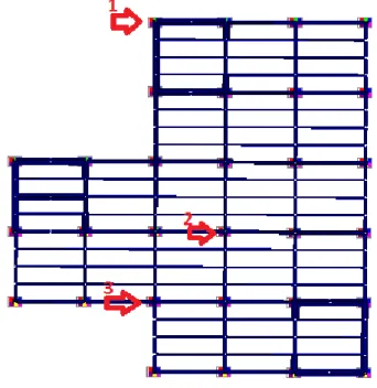
To determine the changes in values of tension and displacement adopted is given constructive scheme of the building in the complex SCAD program. Was selected a building with irregular shape, consisting of two blocks. First block is a 14 -storey building wit h a typical step column 6x6 m. Size in terms of 18 x30. Floor height of 3 m. The second unit is a 10 -story building the size of 9x9 m in plan , with a steel frame and rigid system of vertical connections.
36
Fig.4.2. Design model plan
The procedure for forming the structural scheme of the building in the complex SCAD program:
- create a design model;
- will appoint stringent specifications of elements
(elements sections taken according to calculations by the first and second group of boundary conditions)
- Assign a fastening column (tough conditions of stability) - to apply load (own weight, snow, wind, poleznaya load) - create a DCS (enter coefficients depending on the
duration of load and consider mutually exclusive load) - Check the permissible limit voltage and displacement - to apply dynamic load (seismic force prykladyvaem 5,
37
- - choose characteristic analysis of constructions (columns, beams)
- - perform the calculation buildings - - analyze the result
Table 4.1 - The coefficients for the combination of static loads.
Types of stress The coefficient
combinations, NC
1 Constant load 1
2 Long Load 0.95
3 Short load 0.9
Table 4.2 - Values of coefficients for the seismic load combinations.
4.1. Methods of analysis of the calculation results
When processing data for the research results increase forces and displacements in the frame of the building with the variable number of floors of the seismic loading perform:
- analysis of the calculation results determined efforts and move from static load and DCS at certain points (nodes at abutment floor to ceiling columns), the values recorded in the table. The points, which are determined efforts and move selected b ased on their structural significance - abutment junction of the main beams to
Types of stress The coefficient
combinations, NC 1 Constant for concrete, stone and wooden
structures
0.9
2 The same for metal constructions 0.95
3 Temporary prolonged 0.8
38
columns, as well as the maximum in these forces and displacements;
- determine the movement of forces and seismic load of the same points (nodes at the overlap floor on pillars), the values recorded in the table;
- compare the significance of the values with valid regulations. If the values exceed permissible - wonder new baseline data;
- compare the significance of the values and express their attitude in %.
When processing data for the research results determine the degree of influence of seismic loading on the skeleton of the building depending on the intensity of the earthquake:
- determine the movement of forces and seismic loads at certain points (nodes at the overlap floor on p illars), the values recorded in the table;
- compare the significance of the values with valid
regulations. Determine whether it is possible reduce the impact of seismic loading on the skeleton of the
building. If yes - then adjust the estimated model building;
- compare the significance of the values and express their increase in%.
4.2. Initial data studied building.
Initial data:
- altitude - 119 m; - wind area - 1;
39
- the building frame type; - frame - steel;
- number of floors -14; - building height - 42 m; - floor height - 3.0 m;
- the basic step of columns - 6 x 6 m;
- column welded intersection 356h406h393; - main beam - dvutavr №36,
- -dvutavr deck beams №24; - Step main beams - 6 pm; - a step deck girders - 1.5 m;
- the main beams are placed in the longitudinal direction; - overlap - precast concrete;
- slab thickness - 220 mm; - coating thickness - 200 mm.
The design of the building.
In the SCAD program complex was developed calculation model building. Types of finite elements - spatial shaft (Fig. 4.3.).
Quantitative characteristics of the design scheme.
Design model is characterized by the following parameters:
Number of elements - 1581
Finite Element number - 4551
The total number of unknown displacement and r otation - 381648
Number of downloads - 15
40
Fig.4.3. Diagram public buildings
Conclusions:
1. A calculation model of the building in the complex SCAD program.
2. Before the calculation model applied static and seismic loading.
41
4. For the calculation takes 6 forms with different periods :
Form 1 period 2 .67 s ec Form 2 period 2. 21 s ec Form 3 period 1. 69 s ec Form 4 period 0.87s ec Form 5 period 0.70 s ec Form 6 period 0.59 s ec.
For values entered in the table, form 2 was adopted for a period of 2.21 seconds. As the most unfavorable with the maximum values of stresses and displacements.
42
Chapter 5
Result analysis
5.1. Introduction
To study the chеnges of stresses and displacements in steel frame public buildings was applied load at 5, 6, and 7 points. For selected for analysis items the frame of the building calculate the stress and displacement under seismic loading and comparable static. Depending on how many times the increased examined characteristics will depend recommended ways to increase seismic frame.
5.2. Calculation and analysis of stresses and displacements in the metal frame of the building static loads.
The calculation considered the most unfavorable combination of loads. Until such schemes applied load, self -weight construction, wind and snow load payload. Loading collected in the estimated load combination with appropriate coefficients. After loading and calculation were obtaine d the following results:
43
Paul stresses Nx at calculation of the combination of efforts
44
Mu stress field in the calculation of the combination of efforts
45
Displacement the X axis, mm.
46
Displacement on axis Z, mm.
47
Static movement building: H / 500≥Δ = 42000/500 = 84mm ≥62,27 mm; - the condition is met. The stability of the building is provided.
Analyze the data obtained and is listed in the table (Table. 5.1.1). To choose the analysis of characteristic elements, such as c olumns and main beams in the first, fifth, tenth and chotyrnadtsyatomu floors. Fig. 5.1.1. and 5.1.2. shows selected columns and beam analysis, respectively.
48
Figure 5.1.2. Selected main beam analysis
Table 5.1.1. stresses and displacements from static loads
Item number
Floor number Force Stress,
σ, kg / cm2 Displacement, Δ, mm My, kg · cm Mz, kg · cm N, kg 1 1 (0.000) -363206.7 64379.42 -300046 1,990.27 3.57 1 5 (15.000) -213611.2 132,239.1 -174634 1,608.47 12.25 1 10 (30.000) -150490.6 93237 -109663 1651.1 27.1 1 14 (42.000) 71949.24 66956.79 66696.7 1516.28 36.62 2 1 (0.000) -45709.91 -811,883.5 -1254356 2160.5 7.18 2 5 (15.000) -226602.8 -724072, -897682.9 2127.8 21,22 2 10 (30.000) -337310.9 -651891.3 -417864.3 2140.24 37.75 2 14 (42.000) -34261.1 -219085.6 -28092.84 1509.56 45.12 3 1 (0.000) -1309034 -590325.8 -1126493 2129.31 6.35 3 5 (15.000) -1106730 -503194.9 -793651.8 2049.14 18.54 3 10 (30.000) -1142352 -291549.7 -318046.6 1599.5 32,12
49 3 14 (42.000) 1375766.6 -95315.43 -16223.79 1582.9 36.76 4 1 (0.000) -664893.5 -4064.69 26372.35 1577.7 4.32 4 5 (15.000) -653786.1 -1459.95 33184.26 1536.4 11.02 4 10 (30.000) -726061.6 1094.23 17862.4 1580.7 27.69 4 14 (42.000) 527242.5 -6776.99 -812.3 1417.6 36.62 5 1 (0.000) -1912850 -232.45 494.32 2173.45 5.36 5 5 (15.000) 1927166.3 108.38 394.01 2192.7 21.0 5 10 (30.000) 1822982.4 -369.31 313.41 2052.6 43,44 5 14 (42.000) 147,257.3 305.8 -366.13 1543.8 52.25 6 1 (0.000) -665030.3 -761.2 -47.07 1494.7 7,17 6 5 (15.000) 749377.4 681.5 87.8 1510.6 20.36 6 10 (30.000) -674555 -53.55 177.15 1519.9 35.99 6 14 (42.000) 771974.2 -77.07 48.09 1540.8 38,27
Further results will need to compare the stress and displacement values under seismic loading 5.6 and 7 points.
5.3. Calculation and analysis of stresses and displacements in the metal frame of the building from seismic load intensity of 5 points.
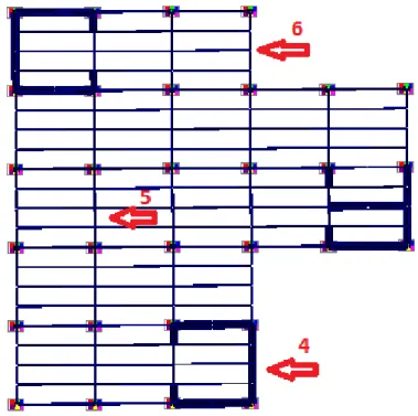
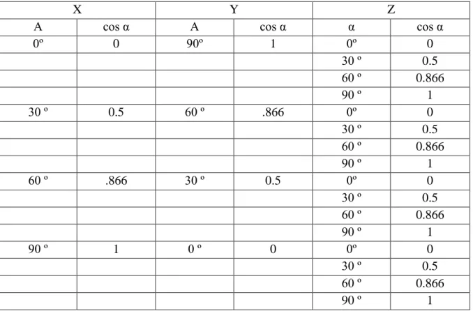
The building is not symmetrical in plan. Identify ways in which we get the greatest pressure and movement changes from cosine angles between the directions of movement vector and seismic action.
For this:
- Composition table of cosines for the application of seismic loading (tab. 5.2.1).
- will make seismic loads to the frame of the build ing at angles every 30˚, setting the direction of its actions through cosines of angles;
50
- analyze the results and make conclusions.
Table 5.2.1.angles to cosines and their application of seismic loading
X Y Z
Α cos α Α cos α α cos α
0º 0 90º 1 0º 0 30 º 0.5 60 º 0.866 90 º 1 30 º 0.5 60 º .866 0º 0 30 º 0.5 60 º 0.866 90 º 1 60 º .866 30 º 0.5 0º 0 30 º 0.5 60 º 0.866 90 º 1 90 º 1 0 º 0 0º 0 30 º 0.5 60 º 0.866 90 º 1
51
NX at X0 Y90 Z0
52
Displacement on axis X mm at X0 Y90 Z0
53
Displacement on axis Z, mm, X0 Y90 Z0
54
NX at X30 Y90 Z0
55
MY at X30 Y90 Z0
56
Displacement the axis Y, mm at X30 Y90 Z0
57
Total displacement mm at X30 Y90 Z0
58
MX at X60 Y90 Z0
59
Displacement the axis Y, mm at X60 Y90 Z0
60
Total displacement mm at X60 Y90 Z0
61
MX at X90 Y90 Z0
62
Displacement on axis X mm at X90 Y90 Z0
63
Displacement on axis Z, mm at X90 Y90 Z0
64
Analyzing these data we can see that the greatest pressure and moving the points appear when the acceleration vector grounds directed along the principal axes X, Y, Z. To analyze the results of calculation to be mentioned in the direction of the principal axes.
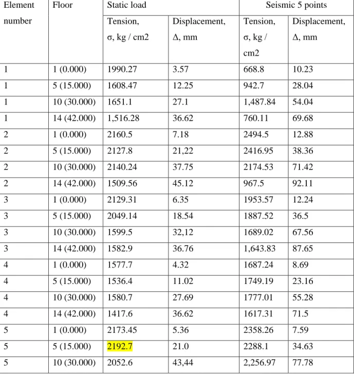
Analyze how much stress and displacement have changed in specific locations (tabl.5.2.2.).
Table 5.2.2.-Comparison of static and seismic load in 5 points for selected elements
Element number
Floor Static load Seismic 5 points
Tension, σ, kg / cm2 Displacement, Δ, mm Tension, σ, kg / cm2 Displacement, Δ, mm 1 1 (0.000) 1990.27 3.57 668.8 10.23 1 5 (15.000) 1608.47 12.25 942.7 28.04 1 10 (30.000) 1651.1 27.1 1,487.84 54.04 1 14 (42.000) 1,516.28 36.62 760.11 69.68 2 1 (0.000) 2160.5 7.18 2494.5 12.88 2 5 (15.000) 2127.8 21,22 2416.95 38.36 2 10 (30.000) 2140.24 37.75 2174.53 71.42 2 14 (42.000) 1509.56 45.12 967.5 92.11 3 1 (0.000) 2129.31 6.35 1953.57 12.24 3 5 (15.000) 2049.14 18.54 1887.52 36.5 3 10 (30.000) 1599.5 32,12 1689.02 67.56 3 14 (42.000) 1582.9 36.76 1,643.83 87.65 4 1 (0.000) 1577.7 4.32 1687.24 8.69 4 5 (15.000) 1536.4 11.02 1749.19 23.16 4 10 (30.000) 1580.7 27.69 1777.01 55.28 4 14 (42.000) 1417.6 36.62 1617.31 71.5 5 1 (0.000) 2173.45 5.36 2358.26 7.59 5 5 (15.000) 2192.7 21.0 2288.1 34.63 5 10 (30.000) 2052.6 43,44 2,256.97 77.78
65 5 14 (42.000) 1543.8 52.25 1727.24 100.06 6 1 (0.000) 1494.7 7,17 2641.65 8.38 6 5 (15.000) 1510.6 20.36 2668.20 33.26 6 10 (30.000) 1519.9 35.99 2566.14 71.96 6 14 (42.000) 1540.8 38,27 1682.98 93.44
According to data obtained conclusions can be drawn:
- Premischennya frame buildings with seismic intensity exercise 5 points to 1.6 times the maximum allowable.
- The stresses in the elements at seycmichnomu load intensity of 5 points in the columns of the first floor of the middle row has increased 1.2 times, and the tension in the main beams 10 and 14 floors increased 1.7 times.
5.4. Calculation and analysis of stresses and displacements in the metal frame of the building from seismic load intensity of 6 points.
After analyzing the data in the previous section, it was
determined that the greatest pressure and moving the points appear when the acceleration vector grounds directed along the principal axes X, Y, Z. Therefore, to analyze the results of calculation to be mentioned in the direction of the main axes.
66
NX at X90 Y90 Z0
67
MY at X90 Y90 Z0
68
Displacement the axis Y, mm at X90 Y90 Z0
69
Total displacement mm at X90 Y90 Z0
Analyze how much stress and displacement have changed in specific locations (tabl.5.3.1.).
Table 5.3.1. Comparison of static and seismic load in 6 points for selected elements
Element number
Floor Static load Seismic 6 points
Tension, σ, kg / cm2 Displacement, Δ, mm Tension, σ, kg / cm2 Displacement, Δ, mm 1 1 (0.000) 1990.27 3.57 2104.7 28.63 1 5 (15.000) 1608.47 12.25 2264.74 75.58 1 10 (30.000) 1651.1 27.1 1450.59 144.32 1 14 (42.000) 1516.28 36.62 1,491.58 190.42 2 1 (0.000) 2160.5 7.18 3207.3 29.72 2 5 (15.000) 2127.8 21,22 3223.97 87.06
70 2 10 (30.000) 2140.24 37.75 2767.6 166.18 2 14 (42.000) 1509.56 45.12 1905.4 219.28 3 1 (0.000) 2129.31 6.35 2425.48 27.68 3 5 (15.000) 2049.14 18.54 2438.78 81.43 3 10 (30.000) 1599.5 32,12 1962.19 155.41 3 14 (42.000) 1582.9 36.76 1503.15 206.07 4 1 (0.000) 1577.7 4.32 1913.21 22.28 4 5 (15.000) 1536.4 11.02 1634.46 59.74 4 10 (30.000) 1580.7 27.69 1597.55 144.32 4 14 (42.000) 1417.6 36.62 1502.79 190.42 5 1 (0.000) 2173.45 5.36 2645.57 16.65 5 5 (15.000) 2192.7 21.0 2528.65 79.04 5 10 (30.000) 2052.6 43,44 2406.7 185.15 5 14 (42.000) 1543.8 52.25 1611.22 243.09 6 1 (0.000) 1494.7 7,17 2882.76 15.81 6 5 (15.000) 1510.6 20.36 2813.8 71.2 6 10 (30.000) 1519.9 35.99 2700.66 165.61 6 14 (42.000) 1540.8 38,27 1930.79 219.92
According to data obtained conclusions can be drawn:
- Premischennya frame building under seismic loading intensity 6 points to 3.5 times the maximum allowable.
- The stresses in the elements at seycmichnomu exercise intensity by 6 points in the columns of the first floor of the middle row has increased 1.5 times, and the te nsion in the main beams increased by 2 times.
5.5. Calculation and analysis of stresses and displacements in the metal frame of the building from seismic load intensity of 7 points.
Similarly, section 5.3. perform the calculation and analysis of stresses and displacements of the seismic load intensity of 7 points.
71
In the specific elements chosen for analysis in Table 5.4.1'll show change stresses and displacements.
72
MX at X90 Y90 Z0
73
Move on axis X mm at X90 Y90 Z0
74
Move on axis Z, mm at X90 Y90 Z0
75
Analyze how much stress and displacement have changed in specific locations (tabl.5.4.1.).
Table 5.4.1. Comparison of static and seismic load in 7 points for selected elements
Element number
Floor Static load Seismic 7 points
Tension, σ, kg / cm2 Displacement, Δ, mm Tension, σ, kg / cm2 Displacement, Δ, mm 1 1 (0.000) 1990.27 3.57 5607.6 56.74 1 5 (15.000) 1608.47 12.25 1243.06 149.33 1 10 (30.000) 1651.1 27.1 1784.52 258.73 1 14 (42.000) 1516.28 36.62 1435.13 378.22 2 1 (0.000) 2160.5 7.18 4632.88 56.14 2 5 (15.000) 2127.8 21,22 4837.94 164.17 2 10 (30.000) 2140.24 37.75 5332.21 315.65 2 14 (42.000) 1509.56 45.12 3857.86 419.95 3 1 (0.000) 2129.31 6.35 3349.31 52.61 3 5 (15.000) 2049.14 18.54 3550.67 154.69 3 10 (30.000) 1599.5 32,12 3267.07 297.74 3 14 (42.000) 1582.9 36.76 2067.13 398.21 4 1 (0.000) 1577.7 4.32 3347.18 43.09 4 5 (15.000) 1536.4 11.02 1653.11 122.45 4 10 (30.000) 1580.7 27.69 1929.65 284.51 4 14 (42.000) 1417.6 36.62 1643.19 378.22 5 1 (0.000) 2,173.45 5.36 3225.79 31.26 5 5 (15.000) 2192.7 21.0 3012.82 149.31 5 10 (30.000) 2052.6 43,44 2711.89 350.69 5 14 (42.000) 1543.8 52.25 2420.61 462.61 6 1 (0.000) 1494.7 7,17 3362.41 29.17 6 5 (15.000) 1510.6 20.36 3,113.77 135.11 6 10 (30.000) 1519.9 35.99 2964.82 317.81 6 14 (42.000) 1540.8 38,27 1920.45 424.81
76
5.6. Final commens
According to data obtained conclusions can be drawn:
- Premischennya frame building under seismic loading intensity 7 points to 6.5 times the maximum allowable.
- The stresses in the elements at seycmichnomu exercise intensity by 6 points in the columns of the first floor of the middle row increased by 2 times, and the tensi on in the main beams increased by 2.1 times.
77
Chapter 6
Methods seismic
protection
6.1.General features methods.
General classification systems seismic protection structures shown in Fig. 6.1.[6] It consists of traditional methods of seismic and special means seismic protection .
Fig. 6.1. Seismic protection classification methods.
6.2. Traditional methods provide earthquake resistance.
1. The brick building. Brick buildings up to four floors is
the most common type of buildings in seismic areas.
Strength and deformation properties of stone masonry such that they do not resist the action of seismic loads. Vulnerabilities
78
buildings in earthquake areas is a combination of longitudinal and transverse walls. The action of horizontal forces in the plane of overlap shear hardest in areas perceived connections overlap with the walls. Therefore, the stone walls are arranged individual -concrete inclusion, which significantly increase the carrying capacity of masonry structures.
In buildings wall stability and the stiffness of the bearing walls of reinforced concrete reinforced strapping zamonolichuvannya, seismic zones and seismic core.
2. Frame building. The construction of large buildings in seismic areas considered more appropriate, because they are about 2 times lighter than brick and have higher spatial rigidity. New buildings of reinforced concrete structures can withstand tremors measuring up to 8 points or more.
Frame-building to improve the mechanical strength should be designed with longitudinal and transverse bearing walls, combined with each other and with floors and surfaces in a single spatial system that takes seismic loads. Exterior walls are counting on the horizontal load. In buildings over 5 floors using panels with double reinforcement. Overlap panel recommend that "the room" with grooved edges.
3 Prefab building. In frame buildings design that takes horizontal seismic load can be: frame, frame with filling, frame with vertical relationships, diaphragms or cores rigidity. For seismic perception of hard concrete frame building components to be reinforced using welded, spiral or closed clamps.
In frame buildings account for more horizontal seismic loads, setting the aperture and ligaments. Some e arthquakes cause the


![Table 2.4.1 - MSK-64 [21]](https://thumb-eu.123doks.com/thumbv2/123dok_br/18383967.892649/25.892.104.794.584.1145/table-msk.webp)
![Fig. 2.4.1: SRF cards in Ukraine.[1]](https://thumb-eu.123doks.com/thumbv2/123dok_br/18383967.892649/38.892.107.785.103.540/fig-srf-cards-in-ukraine.webp)