Universidade do Minho
Escola de Engenharia
Manuel Antynio Freitas de Sousa
Safety Critical Interactive Computing
Systems' Modelling
Dissertação de Mestrado
Escola de Engenharia
Departamento de Informitica
Manuel Antynio Freitas de Sousa
Safety Critical Interactive Computing
Systems' Modelling
Mestrado de Informática
Trabalho realizado sob orientação de
Professor Josp Creissac Campos
Dra. Miriam C. Bergue Alves
Acknowledgements
I would like to thank everyone who helped me during this time.
I would like to thank to my supervisor, Professor José Creissac Campos (Uni-versidade do Minho) and my co-supervisor Miriam C. Bergue Alves (Institute of Aeronautics and Space - Brazil).
Special thanks to my mother, my father and my brother Bruno, for supporting me and giving motivation, especially when it tends to disappear.
Resumo
Normalmente, testar um sistema interativo envolve testar manualmente as pos-síveis interações com ele. Uma vez que esta é uma abordagem manual, torna-se muito caro verificar todas as interacções possíveis. Em sistemas interactivos de segurança crítica esta tarefa é essencial. Uma forma de ultrapassar este prob-lema é a utilização de ferramentas de análise sistemática. IVY Workbench é uma dessas ferramentas. Pretendemos aplicá-la para realizar a verificação de um Sis-tema Interactivo de Segurança Crítica. Os objetivos para esta dissertação são: de-senvolver um conjunto de modelos de sistemas interactivos de segurança crítica, verificar propriedades relevantes dos modelos, fazer uma avaliação crítica do pro-cesso de modelação e sugerir melhorias para a ferramenta e linguagem.
Abstract
Typically, testing an interactive system involves manually testing their possible interactions. Since this is a manual process, it becomes very costly to check all possible interactions. In safety critical interactive systems this task is essential. One way to overcome this problem is to use tools for systematic analysis. IVY Workbench is one of these tools. We plan to apply it to perform verification of Safety Critical Interactive Systems. The objectives for this dissertation are: de-velopment of a set of models of safety critical interactive systems; verification of relevant properties of the models; critical assessment of the modelling process and suggestion of improvements to the tool and language.
Contents
Figures ix Tables xi Glossary xiii 1 Introduction 1 1.1 Motivation . . . 21.2 Research Methodology and Goals . . . 3
1.3 Structure of the Document . . . 4
2 State-of-the-art 5 2.1 PetShop . . . . 5
2.2 VEG toolkit . . . . 7
2.3 Symbolic Analysis Laboratory . . . . 9
2.4 IVY Workbench . . . 11
2.5 Conclusion . . . 12
3 Modelling in the IVY wokbench 15 3.1 The MAL Interactors language . . . 15
3.2 CTL – Computational Tree Logic . . . 18
3.3 Conclusion . . . 19
4 TPGS – a Case Study 21 4.1 Overall architecture of the System . . . 21
4.2 User Interfaces . . . 23
4.3 Selecting components for analysis . . . 23
4.4 Modelling Strategies . . . 24 vii
4.5 Conclusion . . . 25
5 EV Subsystem 27 5.1 Structure of the model . . . 27
5.2 Navigation between screens . . . 28
5.3 Modelling the variables and the screens . . . 30
5.3.1 Variables . . . 30
5.3.2 Screens . . . 33
5.3.3 Alarms and Alerts panels . . . 35
5.3.4 Coordination between the screens . . . 37
5.3.5 Adding the SIN screen . . . 39
5.4 Adding another variable . . . 41
5.5 Variables description . . . 45
5.6 Conclusion . . . 46
6 CR Subsystem 49 6.1 “Business layer” . . . 49
6.2 Navigation between screens . . . 52
6.3 Variables . . . 53 6.4 Voo Screen . . . 54 6.5 Automatic Sequence . . . 57 6.6 Conclusion . . . 59 7 Analysis 61 7.1 Model Analysis . . . 61 7.2 Performance considerations . . . 62 7.3 Tool analysis . . . 66
7.3.1 Language enhancements and limitations . . . 66
7.3.2 New tool features . . . 68
7.4 Conclusion . . . 69
8 Conclusions and Future Work 71 8.1 Results . . . 71
List of Figures
2.1 SAL context example. . . 10
3.1 Interactor example. . . 16
3.2 Branching Time. . . 19
4.1 The PTGS’s macro architecture. . . 22
4.2 An hierarchy of interactors. . . 25
5.1 The models’s macro architecture. . . 28
7.1 Trace of the counterexample (main Interactor only). . . 62
7.2 Trace of the counterexample. . . 63
7.3 Verification times of CR model. . . 64
7.4 Verification times of EV model. . . 65
7.5 Communication between Interactors. . . 68
List of Tables
2.1 Summary of the analysis. . . 13 5.1 EV model figures. . . 47 6.1 CR model figures. . . 60
Glossary
B
BDD Binary Decision Diagram, p. 10.
BNF Backus Normal Form or Backus-Naur Form, p. 7.
C
CR Electric Control Network, p. xi. CTL Computation Tree Logic, p. 5.
E
EV Flight Events Sequence Network, p. xi.
G
GUI Graphical User Interface, p. 7.
I
IAE Institute of Aeronautics and Space - Brazil, p. 3. ICO Interactive Cooperative Object, p. 5.
L
LTL Linear Temporal Logic, p. 5. xiii
M
MAL Modal Action Logic, p. 4.
MSI Inertial Sensor Module, p. 55.
O
ObCS Object Control Structure, p. 6.
S
SAL Symbolic Analysis Laboratory, p. 9.
SMT Satisfiability Modulo Theories, p. 10.
SOAB-CDB Onboard Flight Control Software-VLS Onboard Computer, p. 55.
T
TPGS Testing and Preparation Ground System, p. 3.
V
VEG Visual Event Grammars, p. 7.
X
Chapter 1
Introduction
Nowadays interactive systems are everywhere, so problems that resulted from interactions with these systems appear more frequently. As systems becomes more complex, and with more features, interaction with them becomes more com-plex too. Like any other piece of software, interactive systems need to be analysed to guarantee their quality. In this kind of systems, evaluation can be performed, for example, with respect to how easy the system is to learn, how perceivable the presented information is, or how predictable the system is. However, it must also be considered whether the system prevents errors, and always behaves correctly. We are interested in techniques that systematically verify Interactive Systems with respect to safety. By safety we mean that the system is free from errors and we want to establish that all possible interactions do not trigger any error or erroneous behaviour. To achieve that, we focused in the exhaustive analysis of all possible system behaviour.
Several techniques are available to perform evaluation of interactive systems ranging from empirical studies with users to inspections performed by usability experts (see [11] for a good coverage of this topic). Typically the techniques are not systematic and they consume too many resources (usually time and financial cost) to achieve quality results. Besides, the studies results cannot guarantee safety, since the techniques are not exhaustive in their analysis. To achieve exhaustive verification of Interactive Systems, we will analyse formal methods that allow it applicability, for systematic verification. This will guarantee that if a system’s property is proven/demonstrated, then we can be sure that it always holds for that system. Such warranty is required since, we will apply this kind of analysis
to Safety Critical Interactive Systems.
1.1
Motivation
Evaluation of interactive systems should be done during the development cycle, and not at its end. In chapter 9 of their book on Human Computer Interaction, Dix et al. [11] discuss several approaches to the evaluation of Interactive Sys-tems. They distinguish evaluation techniques according to who is involved: the designer/usability expert or the user. Some techniques are carried out only by designers/usability experts, others need common users to be performed.
Evaluation of an Interactive System may have several objectives, which can be evaluate the reachability of system functionalities, evaluate the users’ interaction experience, or identify any specific problem with the system. The book describes several techniques like cognitive walkthrough, which main goal is to establish how easy a system is to learn, heuristic evaluation, experimental evaluation, observa-tion, queries and evaluation through monitoring physiological responses. Some of them are performed by experts. Others, analysis of data obtained through user experiences with the system. In an experimental evaluation, an evaluator chooses one or more hypothesis to be tested, and experiments are performed with a sig-nificant number of potential target users and the data from the experiments is collected for later analysis. This technique can be seen as bug finding, in the sense that, errors are “caught” in the collected data of the experiences. However, bug finding is just not enough to perform verification in Safety Critical Interactive Systems, as the user could miss some critical interaction with the System.
An Interactive System is safety critical when its failures can lead to loss of human lives, or loss of a large amount of money, or even both. Examples of such systems can be found in aeronautics and space, aviation, banking, health or even sports. Sport might not be an obvious area, but safety-critical interactions exists mostly in motorsport systems. For example, a steering wheel of a Formula 1 (F1) car, or a telemetric monitoring system, are Interactive Systems whose failure could cause loss of lives (pilot or even audience) and loss of quite large amount of money (a top team F1 car may cost 2-3 million euros).
Another problem with “traditional” techniques is that they require a consider-able amount of usability expertise (knowledge of the principles and guidelines),
1.2. RESEARCH METHODOLOGY AND GOALS 3 time (to observe user interactions) and resources (users to perform experiences), to get accurate results, and that they cannot be performed automatically. All the techniques presented above cannot verify Interactive System, they just give indi-cations at the level of usability and proper operation of what was tested, but not in an exhaustive manner, which is not enough for Safety Critical Interactive Systems. One way to achieve systematic analysis is by using formal i.e., mathematically rigorous, methods. Formal analysis of Safety Critical Interactive Systems has been applied to a number of interactive systems in aviation and health. These analysis were able to find problems with either security [2, 16] or disrespect for good prac-tice in interface design [18]. Some concepts like graph theory were also applied [19]. The IVY Workbench has been applied to some realistic case studies [6, 7, 8], and there is interest in exploring its applicability to Safety Critical Interactive Com-puting Systems in the space domain.
The system under consideration is Brazilian Aeronautics and Space Institute’s (IAE) current satellite launcher Testing and Preparation Ground System (TPGS). TPGS includes several operators’ interactions that enable control over the teleme-try and other aspects of the preparation and launching of the rocket. Each inter-face screen enables interaction between the operator and the system via a graph-ical user interface.
1.2
Research Methodology and Goals
The main objective of this research is to apply IVY Workbench to the IAE’s TPGS, which is a critical system supporting space mission preparation. The adopted research methodology follows the activities below:
• review the recent and state-of-the-art publications;
• study the system to model based on the user manuals and remote interaction with the IAE’ researchers;
• develop a set of models of the IAE’ TPGS;
• test critical properties over the developed models.
Although the IVY Workbench had been chosen from the outset as the tool to model TPGS, the analysis of similar tools was required in order to understand how better
and appropriate the IVY Workbench is when compared to them. Another particu-larity is that the system was modelled based on the user manual and not on the actual system.
The objectives of the research then are:
• to develop a set of models of the system addressing different modelling ap-proaches;
• perform properties verification over the models;
• propose improvements and new features in both the language and the tool based on the modelling process results.
1.3
Structure of the Document
This document is organized as follows. Chapter 2 contains an analysis of some tools used to model and verify Interactive Systems. The main characteristics of the tools are described, and a comparison between them is made.
In Chapter 3, the language used to model the system under study, the MAL Interactors language, is described. The structure of an Interactor is introduced, alongside with what can be expressed with the language.
Chapter 4 introduces the system to be modelled. What it is used for, its archi-tecture and all its subsystems. Moreover, issues to be addressed in the modelling process are described.
In Chapters 5 and 6 the modelling of two TPGS’s subsystems, Flight Events Se-quence Network (EV) and Electric Control Network (CR) respectively, is described. The obtained models are described step by step and analysed.
In Chapter 7 an analysis of both the models and the tool is made. Concerning the analysis of the models, some verified properties are shown. Data on the veri-fication times obtained in the two machines that performed the tests is analysed. The tool analysis is related to the language improvements and tool changes that can be made in order to reduce the modelling and verification times, and to make the tool more versatile.
The document ends in Chapter 8 with a synthesis of the work done, the con-clusions obtained, and the future work to be carried out.
Chapter 2
State-of-the-art
In the previous chapter we have mentioned that typical user interface evalua-tion techniques are usually not automated and can take a considerable amount of time and resources to apply. Now, we will consider some techniques/formalisms that use model checking to perform automated and exhaustive verification of In-teractive Systems.
Model checking is a technique for formally verifying systems specified as finite-state machines [9]. Desirable properties of the behaviour of the system are ex-pressed as temporal logic formulas [10] (e.g. LTL, CTL), and a traversal of the finite-state machine is performed in order to check if certain defined property holds or not.
Four tools will be considered: PetShop, which uses Petri nets; the VEG toolkit, which uses grammars; SAL (Symbolic Analysis laboratory), a framework that com-bines different verification tools; and the IVY workbench, which uses Modal Action Logic to specify the models.
2.1
PetShop
PetShop1 is an environment to edit, verify, and execute Interactive Cooperative
Objects (ICO) models. Palanque proposed the ICO [15] formalism, which is in-tended to specify interactive systems. ICO is an object-oriented formalism, that can be seen as a class, divided in four different parts:
1http://www.irit.fr/recherches/ICS/softwares/petshop/
• a Data structure which is a set of typed attributes;
• a set of Operations that are called services (part of that set of operations
are also the internal operations that can only be invoked by the object that defines them);
• an object Object Control Structure (ObCS) that defines the behaviour of the
ICO;
• and a Presentation specified by a set of widgets, that connect the user
inter-action with the object’s user services.
The ObCS, besides defining the behaviour of the ICO, defines all behaviour re-garding to the services, such as service availability, service requests processing, services required as a client, and own operations. To represent all these features a high-level Petri Net is used. The Places of the Petri Net, are seen as the states of the system, and the Transitions as the services of the ICO. User interactions, called user services, are represented as ellipses, linked to the corresponding Transition.
Presentation as mentioned above is a set of widgets, and is the only place where the interaction between user and system is performed, so each widget could activate an user service. Each window of an interactive system, is modelled by one ICO and so, the synchronization between ICO’s services are defined in the ObCS.
From this specification it is possible to automatically verify the model. Several tools are available to verify CTL/LTL formulas in Petri Nets, and some interesting properties can be proved (for example, the absence of deadlock). However, be-cause the system is represented in more then one ICO, we need to verify more then one ICO at the same time. This formalism has been applied to various kinds of systems including a plane cockpit display system, an example of a Safety Crit-ical System [1].
One problem in this tool/formalism, and generally in model checking, is the
state space explosion problem. The number of states needed to represent a System
can become massive, making it non viable to analyse all the states either due to processing time/power demands, or due to memory demands. For small systems this problem does not exist, but a real system may have a very large number of states, or even an infinite number. PetShop uses a model checker that represents the states explicitly, so the verification of properties can become too costly, or simply not viable.
2.2. VEG TOOLKIT 7
2.2
VEG toolkit
To resolve the problem of state explosion, Berstel et al.[3] proposed VEG toolkit, which, instead of using Petri Nets, use an extension of BNF grammars to specify GUIs. The idea is to decompose the specification of a large GUI interface into a communicating automata, which reduces the state space [3]. A VEG object represents an automaton and is specified by a grammar representing a small part of the GUI. The specifications are independent of the layout of the GUI, so there is a separation between presentation and behaviour, which makes the reuse of the same behaviour in different presentations possible. The grammar of a VEG object specifies the behaviour, and communication between components by a set of rules, typically with the following format:
<current state> ::= <guard> <communication> <visual action> <goto next state>
Each rule specifies the behaviour of a component in a state. The <current state> is the state we are specifying, the <guard> is the event or set of events that ”trigger” the rule, <communication> is where we send events to other components, and <visual action> is where we specify the visual changes. These changes are programmed independently from the grammar rules, based on the particular presentation toolkit.
Besides the separation of presentation from behaviour, VEG has separation of data and control. As defined above, a specification in VEG is composed by a part that describes the event-driven behaviour of the GUI, and other part describing the manipulation of data. Sometimes these separations need to be bridged. Consider, a simple GUI that reads a number, and shows a mark which turns green or red depending on whether the number is even or odd, respectively. The routine for checking the number is independent from the GUI design, but the result influences the behaviour of the GUI. To model this kind of routines VEG uses Semantic
Func-tions which are collected in the Semantic Library and are written in a programming
language. The result of these functions can be passed to visible actions.
As with the ICO formalism, the verification of VEG specifications is done using model checking. Because a specification in VEG is not an automaton per si, or some structure to which model checking can be directly applied, a translation of the specification to a model that can be verified by a model checker is needed.
Besides that, VEG was designed in a way that makes it easy to translate the specification into an abstraction in order to reduce the state space. VEG toolkit2,
the tool used for specification, verification, design and implementation of graphical user interfaces in VEG, translates VEG specifications to Promela, the language of the SPIN model checker. With SPIN we can test consistency and correctness, detect deadlocks and unreachable states, and generate test cases for validation which is a new feature that we do not have in ICO. The properties to check can only be specified using LTL.
Because the Promela specification is an abstraction of the original VEG specifi-cation, we face new problems: Soundness and Completeness.
For a program P , an error location ε, and an algorithmA that performs abstraction of a system/program:
• A is sound iff A(P, ε) = ”safe” then P is safe w.r.t. ε. • A is complete iff P is safe w.r.t. ε then A(P, ε) = ”safe”.
For this particular case we say that, the algorithm that abstracts the VEG specification to a Promela specification is sound if and only if when some property is true (or false) in the Promela specification then the same property is true (or false) in the VEG specification. The algorithm is complete if and only if when some property is true (or false) in the VEG specification then that property is true (or false) in the Promela specification.
From the undecidability of the halting problem [4], we know that there is no sound and completeA. So there are two approaches: falsification and verification. Falsification is the exploration of a subset of states of the original specification, so this approach is like a bug finder in the sense that, if we find an error it exists in the original specification. On the other hand, if it is not possible to find the error in the abstraction, we can say nothing about the absence of that error, in the original specification. Verification consists on the exploration of a superset of states of the original problem. In this case if we do not find an error it actually do not exists in the original. On the other hand, if we find an error, that error could be actually a genuine error, that can be reproduced in the original specification, or could be spurious, i.e., the error is not feasible in the original specification.
2.3. SYMBOLIC ANALYSIS LABORATORY 9 Apart from these problems model checking can be applied for verification, and VEG formalism was applied to several systems, like an editor similar to Notepad, a graph construction library and a large real medical software application. More than verifying properties, the VEG toolkit can generate Java code of the specified GUI. This is a major difference between the previous formalism, and makes the modelling useful to implement the GUI, which is a good way to attract the industry to use the tool.
2.3
Symbolic Analysis Laboratory
In many examples we might need to represent many numerical variables, and in some cases we might need to represent real numbers with no approximation. SAL is a formalism/tool developed at SRI International3 that has a unique “infinite”
bounded model checker, capable of performing verification in such systems. SAL-env is a framework for combining different tools for abstraction, analysis, theorem proving and model checking of transition system. SALenv has an intermediate language called SAL to specify transition systems, which is similar to input lan-guages used in other verification tools like SMV4, or Murϕ5. The abstract syntax
tree of SAL is specified in XML, which makes this language easy to translate to other modelling and programming languages.
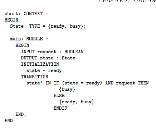
A SAL model is a context, and a context is a container of types, constants, and modules (which represents a transition system). A type can be an enumeration or an infinite set like {x : REAL | x > 0 AND x < 10}. Constants can be seen as global variables of that context, that cannot be changed. A module is where the specification of the transition system is in. Inside a module we have one or more input, output, local, or global variables, an initialization “zone” where we can define initial values for the variables and a definition area where we can define invariants. Still inside a module, we have a transition “zone” where we define the transitions (“steps”) of the system. In Fig. 2.1 we can see an example of a SAL context, that nondeterministically switches its state from ready to busy and vice-versa. Being this language intended to be platform independent, due to its
3http://sal.csl.sri.com/
4http://www.cs.cmu.edu/ modelcheck/smv.html 5http://www.cs.utah.edu/formal_verification/Murphi/
Figure 2.1: SAL context example.
abstract syntax being specified in XML, it is easy to apply several model checkers to a SAL model. In fact, SALenv has several model checkers with many approaches with respect to how the model is abstracted and represented (i.e., BDD-based model checker, SAT Solving, SMT Solving, etc). While there is the possibility to check properties with LTL and CTL, the current version of SAL framework does not print counterexamples for CTL properties, and can only verify CTL properties that can be translated to LTL. In fact, the verification of CTL properties is still experimental.
Another feature present in this framework is the Path Finder, which is a random trace generator. Giving a context and a module of a SAL specification, the Path
Finder randomly generates a trace, where the number of transitions of the generated
trace can also be specified. Like the VEG formalism, SALenv has a automated test generator that generates test cases.
One good feature, that PetShop also has, is the possibility of performing simula-tion over the models. This is a good feature to test specific sequence of acsimula-tions in order to perform a first validation of the model. Something that in traditional temporal logics, like LTL or CTL, is hard to achieve. The simulator available in SAL framework is a command line-like interface.
2.4. IVY WORKBENCH 11
2.4
IVY Workbench
Campos et al. have proposed the IVY Workbench, a similar tool to the previous one, which supports a modelling, verification and analysis cycle of interactive systems. In this tool the Interactor is the main concept used to structure the models. The Interactor concept (Faconti and Paternò, 1990; Duke and Harrison, 1993) was proposed to help designers focus on key issues in interactive systems. An Interactor is a kind of an object capable of representing its state in any rendering environment. Several formal specification languages have been used to specify
In-teractors, like Z and VDM. As SAL, IVY Workbench has an intermediate language
to specify a model, which is an adapted version of Modal Action Logic (MAL) [17]. The definition of an Interactor has three main components:
• State; • Behaviour; • Render.
The State is represented by a set of typed attributes. Actions are used to manipulate the State of the Interactor. The Behaviour is described using an extended version of Structured MAL. In addition to the usual propositional operators and actions the logic provides a modal operator, two deontic operators, and a special reference event to specify the initialization of the state variables. The modal operator defines a relation on the current and next values of attributes, given a particular action. The rendering relation of the Interactor is defined by using the annotation [vis] before an action or an attribute. The annotation before an attribute shows that the attribute is visibly perceivable, when attached to an action, that it can be invoked by the user. The composition of Interactors is done using aggregation. The actions and attributes of an aggregated Interactor are always accessible to the Interactor that aggregates it.
A compiler, i2smv, translates the MAL Interactors model to a Symbolic Model VerifierSMV specification, in order to perform model checking. IVY Workbench has some features to perform the verification and analysis. The tool can be divided in three main components (features):
• PropertiesEditor; • TraceAnalyzer; • WildAniMAL.
The ModelEditor is the component where we write our models using MAL
Inter-actors. Model editting can be done in plain text or using a GUI interface. The PropertiesEditor, as its name suggests, is the section where we can define the
formulas. Formulas can be written in text, as in the ModelEditor, or they can be constructed, using a GUI Wizard, from a set of patterns available in the tool. For the formulas that have been checked false, the model checker generates a trace of a counterexample. The TraceAnalyzer is the component that helps the designer understand why the formulas are checked false. From a formula checked as false, the TraceAnalyzer gets the trace of the counterexample, and then shows it using a number of different representations. The WildAniMAL is the component where the model can be simulated. It helps to test the behaviour of the model by experimentation, which is useful to test simple interactions.
2.5
Conclusion
From the analysis above we have seen that all the tools can verify LTL formulas, and only PetShop and IVY can verify CTL formulas. SAL can verify CTL formulas too, but with a particularity, only CTL formulas that can be translated to LTL. Another difference between the tools relates to the verification techniques that they provide. All the tools verify properties using the model checking technique. The PetShop performs model checking over Petri Nets, the VEG toolkit over a Promela specification and IVY over a SMV specification. The SAL env performs model checking through SAT and BDD-based model checkers. In SAL env is also possible to verify properties through theorem proving with SMT solvers. That makes the SAL env more versatile, specially to verify bigger systems, because theorem provers are faster than model checkers [14] (although it must be noted that this is done at the expense of the fully automated nature of model checking, in particular in the case of liveness). Table 2.1 summarizes the above discussion.
2.5. CONCLUSION 13 Formalism/Tool Specification Abstract Representation Verification
PetShop Petri Net Petri Net LTL, CTL
VEG toolkit Grammar Promela Specification LTL
SAL env SAL Language SMT, SAT, BDD LTL
IVY Workbench MAL Interactors SMV Specification LTL, CTL Table 2.1: Summary of the analysis.
We have seen a number of approaches but the same methodology for verifying an interacting system: design a model of the system and perform verification, either by checking properties (LTL, CTL, etc) or by simulation. One problem with checking properties is that they can be hard to specify. The problem with simulation is that it can take a long time, and we can not be assured that we have gone through all the states. What if we could check a property and simulate at the same time? For example, follow a path of execution, and verify the validity of a certain property. Or check the validity of a certain property, where the user can only use some predefined actions. That kind of analysis and modelling is a task analysis-related, and was used with several formalisms and tools, like ICO, SAL and IVY Workbench. In this approach we restrict/guide the analysis trough a predefined behaviour of the user. This analysis is hard to be done just using temporal logic, and in some cases is just impossible, due to the limited expressiveness of the logics. In ICO and IVY Workbench the “starting point” is the model of the system. Now we need to create a user task model and then perform the typical analysis with the temporal logic. Good examples of this kind of modelling and analysis in ICO and IVY Workbench can be found in [15, 5], respectively. In ICO and IVY Workbench the separation between system model and user model is clear. This enables us to make both analysis without overcomplicating the system model. In IVY we have both models as different Interactors, and only need to create an interactor that will aggregate them and perform the orchestration between them. In ICO the user model only needs to link the user action to the actions in the system.
Chapter 3
Modelling in the IVY wokbench
Section 2.4 provided a brief introduction to the IVY workbench. This is the tool that will be used in the remaining of this dissertation. As such, this chapter provides more details regarding the modelling languages supported by the tool. Two languages are considered: on one side, MAL interactors, the language used to describe the interactive systems; on the other, CTL, the language used to express properties for verification.
3.1
The MAL Interactors language
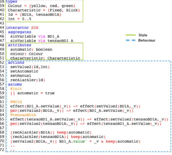
As described in section 2.4 the main concept used to structure MAL Interactor models is the Interactor, which has three main components: state, behaviour and rendering. Figure 3.1 shows two of these components (state and behaviour) in the
SIN Interactor.
The state is represented by typed attributes, as in the example. MAL Interactors have two base types only, the boolean and enumeration types. In figure 3.1 Colour,
Characteristic, Id and Int are enumerated types. Enumerations, as is to be expected,
are defined by explicitly listing all the possible values of the type. When the values are sequential (integer) numbers, the definitions can be simplified by using ranges that indicate the first and last number in the sequence only. Hence, type Int was defined as 0..5, which is is equivalent to explicitly defining the enumeration
{0,1,2,3,4,5}. Besides declaring its own attributes, an interactor can aggregate
other interactors, thus allowing structuring the model (see the aggregates clause in the figure).
Figure 3.1: Interactor example.
Behaviour is defined by a set of actions, in the example they are declared below the attributes. The behaviour of the actions is defined using axioms in MAL logic. These axioms define the semantic in terms of their effect on the state of the Interactor. In addition to the usual propositional operators, the logic provides:
• a modal operator [_] _, which means that if [ac] expr then expr is true in all states reached by the action ac;
• a special reference event [], that means, if [] expr then expr is true in the inicial state(s);
• a deontic operator per, means that if per(ac) then action ac is permitted to happen next;
• a deontic operator obl, means that if obl(ac) then action ac is obliged to happen some time in the future;
3.1. THE MAL INTERACTORS LANGUAGE 17 • operator effect, means that if effect(ac) then action ac happen at the exact
moment
The special reference event [] is used to define the initial values of the attributes, as we can see in line 59 of figure 3.1. In this case, it is being stated that attribute
automatic has the value true in the initial state.
The modal operator is used to define the behaviour of an action, i.e. the effect that the action has on the attributes of the Interactor(s). In the expr part of the modal operator, the next state of an attribute is represented by a prime, as seen in line 70 of the figure 3.1.
Moreover when we want to express that certain attribute remains unchanged the keep operation is used, as seen in line 68 of the figure 3.1. In this case the axiom states that when action recAlarAler happens with value BD1A as parameter, the attribute automatic remains unchanged.
The expressions in lines 68 and 69 are particular cases of the generic expression: [Action] Consequence
This means that when the Action occurs the Consequence happens. From this expression and making use of an implication another generic expression can be defined:
Condition –> [Action] Consequence
Similar to the previous but now the Consequence only happens, if the Action occurs and the Condition is true.
In some situations more than one action have the same consequence. To reduce duplications in the model it is possible to use the following “syntactic sugar”:
[ac1|ac2|ac3] Consequence [!(ac1|ac2|ac3)] Consequence
The first line means that when the actions ac1 or ac2 or ac3 occurs the
Conse-quence happens. The other line means that when any action in the Interactor with
the exception of ac1, ac2,ac3 occurs the Consequence happens.
An action can have parameters as is the case of actions setValue2 and
setAlar-Aler in figure 3.1. Sometimes the definition of an action depends on the values
[ac(_v)] Condition_on_v –> Consequence
This previous expression means that when action ac occurs with values on the parameters that obey Condition_on_v, then Consequence happens.
The deontic operators are used to express permissions. per(Action) –> Condition
This previous expression means that the Action is only allowed to occur if the
Con-dition holds. An example of this kind of expression is in line 63 of figure 3.1. That
expression means that the action setValue2(BD1A,_v) (where _v is implicitly univer-sally quantified) is only allowed, when the action BD1_A.setValue(_v) is happening.
The obl operator is used in similar expressions. obl(Action) –> Condition
This means that if the Condition is true, then the Action must happen in the future. With all these expressions it is now possible to create an entire model.
3.2
CTL – Computational Tree Logic
The language to specify the properties for verification is CTL [10], a branching time logic. The behaviour of a system over time is seen as a tree-like structure (figure 3.2) in which at each moment in time, represented as a node in the tree, there are several possible futures (the branches sprouting from the node). Hence, a concrete behaviour of the system, i.e., a computation path will be a possibly infinite path going down the tree from its root.
Besides the classical logic operators the CTL language has path quantifiers and temporal operators. Temporal operators are:
• A p - meaning that p holds for all computation paths; • E p - meaning that p holds for some computation paths.
These operators are used to describe the branching structure in the computation tree. The temporal operators are:
3.3. CONCLUSION 19 S0 S1 S2 S0 S1 S2 S1 S2 S1 S0 S0 . . . . . . . . .
Figure 3.2: Branching Time.
• F p - meaning that eventually (i.e., in the future) p holds; • G p - meaning that p always holds;
• p U q - meaning that q eventually holds and until then p always holds; These operators are used to describe properties of a path through the tree.
With all these operators we can specify a wide range of properties, including liveness and safety properties. A liveness property asserts that something good does happen eventually. A safety property asserts that something bad does not happen.
In our study case, because most of the properties are defined to check that what was modelled complies with the manual, we will want to specify properties that can give us counter examples to check if the system is behaving as expected.
3.3
Conclusion
This section has introduced the languages used for modelling (MAL interactors) and expressing properties for verification (CTL) in the IVY workbench, the tool which will be used in the remainder of this dissertation. More details about IVY and its modelling language can be found in [6, 8]. For more details about CTL, see, for example, the book by Clarke et al. on model checking [9].
Chapter 4
TPGS – a Case Study
The Testing and Preparation Ground System (TPGS) is a space ground legacy system that has been in use to support space mission preparation for more than 15 years in the Brazilian Space Launcher Program. TPGS’ software components are often updated due to new missions requirements, different rocket configurations, and new operating systems releases. The hardware is occasionally upgraded due to the obsolescence of the TPGS’ equipment.
As main contractors are in charge of the upgrade activities, there is a need to provide a set of user interface requirements for correct mission-safety system operation as the system evolves due to new updates. The goal then, is to study the feasibility of modelling and analysing the user interface of the system with the IVY tool. This will allow the requirements to be formally modelled and verified against critical properties, and used as a requirement baseline (an oracle) for the TPGS during the acceptance phase of new versions of the system.
4.1
Overall architecture of the System
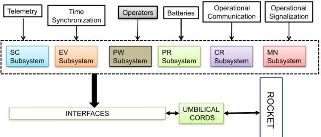
TPGS is a safety-critical system, composed of very specific and customized hardware and software components, responsible for the ground control, testing and preparation of a satellite launch rocket before it is launched. TPGS includes six different subsystems that provide specific functionality during the rocket’s testing and preparation for launching:
PW subsystem: rocket’s power supply, charging and discharging of the rocket’s 21
MN Subsystem SC Subsystem EV Subsystem PR Subsystem CR Subsystem Telemetry Time
Synchronization Operators Batteries
Operational Communication
Operational Signalization
INTERFACES UMBILICAL CORDS
R O C KET PW Subsystem
Figure 4.1: The PTGS’s macro architecture.
batteries.
PR subsystem: rocket’s electro-pneumatic equipment pressurization, activation of the pyrotechnic valves and unplugging of its umbilical cords.
CR subsystem: testing and preparation of the rocket’s control sub-network, includ-ing the initiation of its Inertial Measurement Unit (IMU) and its on-board computer.
SC subsystem: security and safety testing of the rocket’s equipment and the ac-tivation of its security valves during the automatic sequencing for launching. EV subsystem: flight events sequence testing and the activation of the rocket’s
security mechanical devices (SMD) during the automatic sequencing for launch-ing.
MN subsystem: visualization of the information collected during the rocket’s test-ing, preparation and automatic sequencing for launching.
Figure 4.1 shows the macro architecture of TPGS, showing its main subsystems and its external interfaces.
4.2. USER INTERFACES 23
4.2
User Interfaces
The functional requirements for the TPGS were established separately for each subsystem in a 250-page document. The rocket’s preparation process for the flight involves thoroughly checking specific parts of rocket’s electrical network. The operators of each subsystem illustrated in Figure 4.1 must follow a comprehensive preparation checklist that includes procedures and interactions with the rocket’s hardware and software in real-time. The preparation and testing process is mainly based on the user interfaces inputs and outputs. As each TPGS’s subsystem has a specific set of critical procedures to be accomplished, the user interfaces must provide an acceptable level of trustworthiness to deal with this situation.
Each user interface is composed of a number of panels. Some panels present messages to the operator about the state of the system/process, others allow him to interfere in the system/process, for instance running tests. In some cases, graphical representations (i.e. synoptics) are used, while in other case the panels consist mostly of buttons and textual fields. Due to confidentiality constraints, we are not able to describe here the user interfaces in any detail. In any case, it is relevant to note that each panel can contain several tens of user interface components, and that they are interconnected so that events in one panel will affect others. This will become clearer in the description of the models presented in the following chapters.
4.3
Selecting components for analysis
Considering the TPGS’ user interfaces complexity, we decided to select two of the subsystems to apply our approach, the EV subsystem and the CR subsystem. By modeling them, we intended to address two issues:
• determine whether the expressiveness of the language was enough to model the type of user interfaces used in the aerospace field (and study the best approach to model them);
• determine the viability of analysing systems as complex as these (and study the level of detail that could be achieved while maintaining the analysis feasi-ble).
The EV Subsystem is responsible for the testing and preparation of one of the rocket’s electrical sub-networks, where the flight events and the rocket’s security mechanical devices (SMD) are activated. During the rocket’s flight, this sub-net-work is responsible for the sequential activation and control of the pyrotechnic systems in real-time according to a pre-programmed flight strategy.
The CR subsystem is responsible for testing, simulating, and analysing the automatic launch sequence, and monitoring a number of devices in the rocket after the launch.
4.4
Modelling Strategies
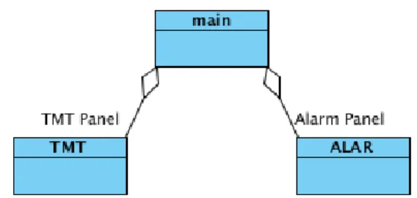
Considering the size of the subsystems being modelled, two main modelling strategies were considered. The first makes use of the Object-oriented features of the MAL Interactor language. Each model becomes a tree-like composition of Interactors (organised through aggregation relations), where each Interactor represents an entity in the interface (e.g. a panel or a control representing the state of a variable in one of the panels). The second strategy uses only one Interactor and models all the interface in that single Interactor. Visually we can see this strategy as a “flat” hierarchy.
It is envisaged that the first strategy will be better in terms of the organisation, maintainability and understandability of the model. One potential problem with this first approach relates to expressing communication between the different Interactors. Communication is achieved by explicit synchronisation on actions or variables’ values between Interactors. Because of the tree-like compositional nature of the language, this can only be done top down in the composition tree. For example, in Figure 4.2 Interactor main knows Interactors TMT and ALAR, but these have no knowledge of each other or of Interactor main. Hence, communication between any two Interactors must be expressed in the Interactor at the root of the subtree they belong to (in the example, main).
One advantage of the first approach is the “reusing” of code. As the modelled system has several variables that record telemetry values, we can simply write a Interactor that captures the behaviour of a variable. Then in the screen that has these variables, we can instantiate as many Interactors as we want to represent the variables. The only code we need to add, besides the aggregation, is the
4.5. CONCLUSION 25
Figure 4.2: An hierarchy of interactors.
synchronization properties.
Besides the strategies to structure the model, strategies for specifying depen-dencies between variables must also be considered. In many cases the value of a variable will depend on the values of other variables in the model. One possibility is to express these dependencies in the definition of actions. Actions will affect these dependent variables differently according to specific conditions expressed as guards in the modal axioms. This will result in more complex modal axioms, and the guards must be repeated for each axioms.
When a variable’s values depends exclusively on other variables (and not on specific actions) an alternative is to use invariants. By their nature, invariants can be useful for more than one action. They are a global property that we assure that is always true.
In Chapter 7 we will further explore the invariants vs. guards approach to expressing dependencies between variables, in particular with respect to verifica-tion performance.
4.5
Conclusion
This chapter has briefly described the system under analysis, the selected subsystems, and the modelling strategies that were considered for the analysis. The next chapters will present the modelling of the selected subsystems.
Chapter 5
EV Subsystem
EV subsystem is the Flight Events Sequence Network. It is a subsystem of TPGS, responsible to test and prepare one of the rocket’s electrical sub-network. In the next section the modelling strategy adopted is explained. In the following sections the modelling of EV subsystem is presented.
5.1
Structure of the model
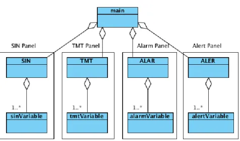
Figure 5.1 shows the architecture of the model. A main Interactor coordinates a number of other Interactors, each corresponding to a different panel in the user interface. In this case four panels are being considered: SIN, a Synoptic panel, shows the EV’s electrical network; TMT, the telemetry panel, show information obtained from the telemetry system; ALAR, the alarms panel, shows messages regarding values that are in the alarm state; ALER, the alerts panel, show messages regarding values that are in the alert state. Each of these panels aggregates variables representing the information they display.
It must be noted that panels Alarm and Alert are special cases. They display the variables which are in an alarm or alert condition in the other panels. Hence, the values of their attributes must be coordinated with the attributes in the other interactors.
Figure 5.1: The models’s macro architecture.
5.2
Navigation between screens
First, we started by modelling the navigation between the screens (one for each panel) of the system. That behaviour was represented in the main Interactor with the variable display with type Screens which is a set of the possible screens. types
Screens = {Principal, Sinotico, MonitTel, aler, alar, ...} interactor main
attributes
[vis] display: Screens actions
sin tmt alarmes ...
There is an initial panel for the operator to login to the system. Only after the operator have successfully logged in the main panel appears. To change between screens the user interface provides a set of buttons. Actions representing each of the buttons hence, the selection of each screen were defined. The actions are all defined in the same way: when an action is triggered, for example sin, the value
5.2. NAVIGATION BETWEEN SCREENS 29 of the display changes to represent the appropriate screen (in the case bellow, the
Sinotico screen):
[sin] display’=Sinotico
As some navigation buttons do not always appear in the screen, some restric-tions have to be made in order to represent this behaviour. The action sin for example, is not available in the access screen, when the system is blocked, and in the exit screen. To represent that, we need to add a permission statement, saying when the action sin can be triggered.
per(sin) -> !(display in {acessoSis,acessoSev,Bloqueio,Escolha,Final})
Other actions are the opposite. They are only available in the access screens. The difference is only in the permission statement.
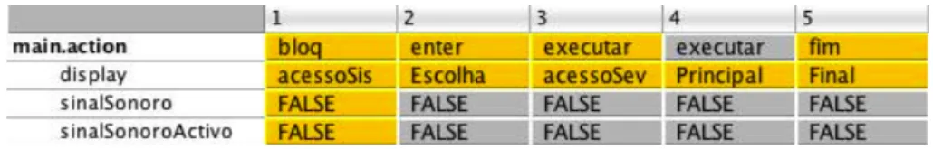
There is a particular action (executar) that appears in three of the screens only. The difference to the other actions is that it behaves differently according to the current screen. The permission statement is similar, but the definition of the action(s) needs to be different. When the screen is in Escolha the next screen after the action is acessoSev, when the screen is either acessoSev or Bloqueio then the next screen in Principal. This behaviour is captured by the following axioms: per(executar) -> (display=Escolha | display=acessoSev | display=Bloqueio) display=Escolha -> [executar] display’=acessoSev
(display=acessoSev | display=Bloqueio) -> [executar] display’=Principal
As we see above the permission statement is quite similar to the previous one. For the action, we wrote two modal axioms. The right side of the implications in the modal axioms (e.g. [executar] display’=acessoSev) is similar to the other actions, the left side (e.g. display=Escolha) is the guard that defines the conditions under which the action is defined (by that particular axiom).
To finalise the modelling of the navigation between screens we only need to define which is the first screen of the system. This is done by adding the initializa-tion axiom bellow.
5.3
Modelling the variables and the screens
Modelling navigation between screens was relatively straightforward the next step was to model the screens. Since each of the screens presents information about a specific aspect of the system (particular cases are the alerts and warning screens that show lists of variables in alert/alarm), the first step was to model, in a general way, the behaviour of a single variable. Then, modelling a screen was the aggregation of a relevant number of variables, with any additional actions and control logic.
5.3.1
Variables
A variable has a value which can change over time, a colour, and an associated characteristic (fixed or blinking). The value of the variable changes according to some underlying system characteristic (e.g. temperature of some specific device). The TMT screen has the more complex variables featuring characteristics such working limits, description, and measurement units. In fact, the variables in the other screens can be derived from TMT screen ones as they only have some of their attributes. To capture all that behaviour we designed the tmtVariable Interactor, which represents a variable of the TMT screen.
types Int = 0..5
Unit = {YES,NO,VOLT}
Colour = {yellow, red, green} Characteristic = {Fixed, Blink} interactor tmtVariable attributes supAlertLim: Int infAlertLim: Int supAlarmLim: Int infAlarmLim: Int value: Int colour: Colour unit: Unit
5.3. MODELLING THE VARIABLES AND THE SCREENS 31 critical: boolean
characteristic: Characteristic actions
setValue(Int)
The Int (integer) type is defined as the values from 0 to 5. Initially was defined from 0 to 10. For our study what is relevant is that we can set a certain integer value for the different states (alert, alarm), so the smaller range is enough. The types Unit, Colour and Characteristic are enumerations with the possible values for the corresponding attributes (unit, colour and characteristic).
As described in the user manual, there are four attributes pertaining to the working limits: supAlertLim (superior alert limit), infAlertLim (inferior alert limit),
supAlarmLim (superior alarm limit) and infAlarmLim (inferior alarm limit). Then
we have the attribute value which represents the value displayed by the variable at each moment, colour which is the colour being used to display the variable, unit represents the unit of the value, critical which states if the variable is critical, and the blinking characteristic defined by the characteristic attribute.
Regarding actions, the action setValue updates the value of the variable. This is the only action needed in this interactor. A first attempt to define it kept all attributes, other than the value, unchanged, as shown the above expression. [setValue(_v)] value’ = _v &
keep(supAlertLim, infAlertLim, supAlarmLim, infAlarmLim, unit, colour, characteristic)
Although the EV allows to set the working limits, we did not model that feature for performance reasons in the verification. In Section 7 we explore those issues further.
The definition above, however, is too simplistic. Changes to the variable’s value can cause alarms or alerts, which in turn can be acknowledged, or not, by the operator. A variable has the colour red and blinks, when its value is in alarm (i.e. the value falls inside the alarm limits), has not been acknowledged by the operator, and is critical. Naturally, since this condition must always hold, it can be said that it is an invariant of the system’s behaviour. However, we did not use invariants for this condition, as will be explained in the next section. Instead, we used guards
on the modal axioms. Hence, for the condition just described the axiom above becomes:
[setValue(_v)]
((_v < infAlarmLim) | (_v > supAlarmLim) & critical)
-> value’ = _v & colour’ = red & error’ = Lim & alarmState’ = AlaNRec & characteristic’ = Blink & keep(supAlertLim,infAlertLim,supAlarmLim,
infAlarmLim,unit,critical,alertState)
The difference to the previous definition is that now we have specified changes to colour and characteristic, and we have introduced new variables error, alarmState and alertState. The guard states under which conditions this particular axiom applies. When the guard is true, a new error is triggered, the colour and the characteristic become red and blink, respectively, and the alarm state is set to non-acknowledged (AlaNRec). Besides this specific axioms, there are four others, defined under the same principle. Together, the axioms cover all the conditions over the working limits and critical condition of the variable expressed in the users’ manual.
The definition of the new variables mentioned above are added to the
tmtVari-able Interactor as:
types ... Error = {Lim,nil} State = {AleRec,AleNRec,AlaRec,AlaNRec,Good} interactor tmtVariable attributes ... error: Error alarmState: State alertState: State
The variable error records what kind of error has been detected, and the varia-bles alarmState and alertState the state of the alarms and alerts, respectively. Because the type State has all the possible states for alarms and alerts, we must constrain the possible value of the alarm and alert state variables, with invariants as seen below.
5.3. MODELLING THE VARIABLES AND THE SCREENS 33 (alarmState!=AleNRec) & (alarmState!=AleRec)
(alertState!=AlaNRec) & (alertState!=AlaRec)
5.3.2
Screens
A model of the TMT screen can now be created by aggregating instances of the
tmtVariable interactor. The TMT screen has a table with more than 30 variables.
Its function is to allow the monitoring of the variables, and as such, there are no actions for the user to perform in the screen itself. However, similarly to variables, the button providing access to this screen (indeed all the buttons providing access to the different screens) has a colour and a blinking characteristic. Two attributes to represent them are added to the model, resulting in the following Interactor: types
Id = {BD1A} ...
interactor TMT aggregates
tmtVariable via BD1_A attributes
characteristic: Characteristic colour: Colour
actions
setValue2(Id,Int)
In this example only one variable (BD1_A) was aggregated to the Interactor. Note that while the screen does not have any action for the user to use, the Interactor defines setValue2 action. This is an internal action used to set the values of the aggregated variables. It was defined to support the coordination invariants in the main Interactor. Furthermore, the Id type was defined as the enumeration of all button names (in this simple illustrative case only one). This enables the definition of setValue2 to be generic. By being parameterized on the name of the button, the action can be defined to set the value of any button.
The working principle of the colour and characteristic attributes for the screens’ access buttons is similar to that of the variables. The button is red and blinks when
at least one critical variable of the screen is in non-acknowledged alarm. As with the variables, the buttons have four more conditions related to the alarm and alert states of the variables contained in the screen. The idea is that the most serious condition (alert or alarm) prevails.
In this case of a single variable we can write the following invariants which directly express each of the rules in the manual:
BD1_A.colour = red -> (colour = red & characteristic = BD1_A.characteristic) (BD1_A.colour = yellow & BD1_A.characteristic = Blink) ->
(colour = yellow & characteristic = Blink)
(BD1_A.colour = yellow & BD1_A.characteristic = Fixed) -> (colour = yellow & characteristic = Fixed)
(BD1_A.colour = green) -> (colour = green & characteristic = Fixed)
For a single variable, we are able to simply say that the colour of the button is the same as the variable. The same applied to the characteristic. With more than one variables the invariant becomes larger and more complex, but the principle is the same. Note that while we could simplify the axioms, leaving them thus makes for a clearer connection to the manual.
Regarding the setValue2 action, we need to synchronize it with the
BD1_A.setVal-ue action. That is, if the variables changes valBD1_A.setVal-ue so should the access button. A
first, tentative, definition is simple: [setValue2(BD1A,_v)] BD1_A.value’ = _v
With this definition we are actually stating that when the set in the screen is triggered, the set in the variable is triggered too (because the value of the variable is being updated). In fact, the system does not work in this way, the system sets the variable and the screen is updated accordingly. We can make this clear by using invariants and permission axioms to express, and force, that when a variable sets his value the screen performs the same action, as shown in the following expression:
effect(BD1_A.setValue(_v)) -> effect(setValue2(BD1A,_v)) per(setValue2(BD1A,_v)) -> effect(BD1_A.setValue(_v))
5.3. MODELLING THE VARIABLES AND THE SCREENS 35 The first implication states that when the BD1_A variable sets its value a set for that variable happens in the screen too (i.e., setValue2 happens when the set of the variable happens). The second implication (a permission axiom) states that
setValue2 for BD1_A is only permitted when BD1_A is set (i.e., setValue2 cannot
happen unless the set of the variable happens).
5.3.3
Alarms and Alerts panels
Aggregating the TMT Interactor to the main Interactor, we now have the naviga-tion and one screen working. The acknowledgement of alarms and alerts is done in the alerts and alarms screens. Hence, we need to add those screens to the model.
The alarms and alerts screens have a list of alarms and errors, respectively, that can be acknowledged by the operator. The same approach used for the TMT screen was followed: defining alerts or alarms variables, and aggregating them to create the screens’ models.
The simpler variable is the alert variable: interactor alertVariable attributes state: State error: Error actions recAlert setState(State)
The alert variable has the attribute error that records the error, and the attribute
state that records the state of the alert (acknowledged or not). The actions are recAlert, to acknowledge the alert, and setState, which is used when a new value is
updated in the TMT screen. Because the type State has the states for alarms and alerts we need to add the following invariant:
(state != AlaNRec & state != AlaRec)
This invariant states that the state of a alert variable can never be in alarm, be it acknowledged or non-acknowledged.
Considering that, as described in the user manual, the only error in the variables is the out of limits condition, we can write the following invariants:
(state = AleRec | state = AleNRec) -> error = Lim (state = Good) -> error = nil
These invariants state that when the variable is in either type of alert, the error is due to an out of limits condition. When a variable is not in alert the error is nil.
The definition of the action recAlert, is straightforward: [recAlert] state’ = AleRec & keep(error)
The action recAlert changes the state to an acknowledged alert, and keeps the error (because the value remains in alert). A constraint is added to the action to avoid recognizing an alert that is already recognized:
per(recAlert) -> state = AleNRec
This constraint means that the action can only happen when the variable is in unacknowledged alert.
The definition of setState is simple too: [setState(_e)] state’ = _e
The variable error is not kept because a error can be triggered. The error’s invariant above maintain the variable correctly set.
As with the TMT variables, we created an Interactor to aggregate the alert variables.
interactor ALER aggregates
alertVariable via BD1_A attributes characteristic: Characteristic colour: Colour actions recAlert(Id) setState(Id,State)
5.3. MODELLING THE VARIABLES AND THE SCREENS 37 This Interactor represents the alert screen and has colour and characteristic (variables colour and characteristic, respectively) in its access button. The invari-ants that state the behaviour of the button are the following:
BD1_A.state = Good -> colour = green & characteristic = Fixed BD1_A.state = AleRec -> (colour = yellow & characteristic = Fixed) BD1_A.state = AleNRec -> (colour = yellow & characteristic = Blink)
When there is no alert in the screen, the access button becomes green and does not blink. When there is at least one acknowledge alert the button becomes yellow and does not blink. Yellow and blinking happens when there is at least one unacknowledged alert. The invariants are only defined for a variable, the first and last implication are easily extended to consider more variables. The middle implication is not so easily extended because of the precedence of alerts. The unacknowledged alert has precedence over the acknowledged alert i.e., if there is an acknowledged alert and an unacknowledged alert, the button becomes yellow and blinks.
The actions’ definitions are similar to those of the TMT screen Interactor. effect(recAlert(BD1A)) -> effect(BD1_A.recAlert)
per(recAlert(BD1A)) -> effect(BD1_A.recAlert)
[recAlert(BD1A)] BD1_A.state’ = AleRec & characteristic’ = Fixed & keep(colour) effect(BD1_A.setState(_e)) -> effect(setState(BD1A,_e))
[setState(BD1A,_e)] BD1_A.state’ = _e
Note that action setState, as setValue2 in the TMT screen, do not keep the variables colour and characteristic. The invariant above guarantees that the values of these variables will be updated as needed.
The alarm screen is similar to this alert screen. The only difference is that instead of yellow, the possible color of the access button is red.
5.3.4
Coordination between the screens
Aggregating the ALER and ALAR Interactors to the main Interactor, we now have three screens. Previously, in the TMT Interactor, we had not added an action to acknowledge alarms and alerts. Because the variables in the alert and alarm