DYNAMICS IN FIRE-INDUCED CEILING-JET
Khadouma Nechab
Final Report of the Thesis Presented to the
School of Technology and Management
Polytechnic Institute of Bragança
To the Fulfilment of the Requirements for the Master of Science Degree in
Industrial Engineering
(Mechanical Engineering branch)
DYNAMICS IN FIRE-INDUCED CEILING-JET
Khadouma Nechab
Final Report of the Thesis Presented to the
School of Technology and Management
Polytechnic Institute of Bragança
To the fulfilment of the Requirements for the Master of Science Degree in
Industrial Engineering
(Mechanical Engineering branch)
Supervisor at IPB: Prof. Dr. Paulo Alexandre Gonçalves Piloto Supervisor at UHBC: Prof. Dr. Abdallah Benarous
ACKNOWLEDGMENT
My thanks go to all the members of the jury, to accept to participate, to contribute to improve this reflection and to stimulate that to come. I thank them for the support and attention they have given us throughout the duration of the thesis.
I would like to express my gratitude to my supervisor at IPB, Portugal, Dr. Paulo Alexandre Gonçalves Piloto. I thank him for having supervised, helped and advised me during the thesis. He was always available whenever i ran into a trouble spot or had a question about my research or writing. He consistently supervised this thesis to be my own work, but steered me in the right direction whenever he thought I needed it.
I would also like to thank to my supervisor at the University Hassiba Benbouali of Chlef (UHBC), Algeria, Dr. Abdallah Benarous for his support. I appreciated the constant help, advices, and support while conducting my thesis.
I would like to express my sincere appreciation to all the professors, researchers and others who, through their words, writings, advice and criticism, have guided my thoughts and have agreed to meet and answer my questions during my research.
I thank my dear parents, who have always been there for me, "You sacrificed everything for your children sparing neither health nor effort. You have given me a magnificent model of toil and perseverance. I am indebted to an education of which I am proud. "
I thank my brothers and sister for their unconditional support and encouragement. I thank all my friends whom I love so much for their sincere friendship and trust and to whom I owe my gratitude and my attachment especially to H Ghania and Z soumia and M Fayssal and K Seddik and A Soufyane, Z abdelkader for help me.
ABSTRACT (EN)
The aim of this thesis is to test the ability of some correlative models to recover both dynamic and thermal characteristics of a fire induced ceiling-jet flow. The flow occurs when the fire plume impinges the ceiling and develops in the radial direction of the fire axis. These correlative models were also compared with a two-zone model (CFAST) and with an advanced calculation method (Computational Fluid Dynamics) for the calculation of the temperature and velocity near the ceiling. These calculations were developed inside an open car park, using different fire events (localized fires).
Both temperature and velocity predictions are decisive for sprinklers positioning, fire alarms positions, detectors positions and activation times and back-layering predictions. Simple graphs were depicted for the time of the fire event and another ones were depicted for the maximum value expected during the fire event.
Some correlative models agree well with the results obtained with CFAST. The CFD results over predicted the dynamics of the fire events.
ABSTRACT (PT)
O objetivo desta tese é testar a capacidade de alguns modelos correlativos para descrever as características dinâmicas e térmicas de um fluxo de jato de teto induzido por um incêndio. O fluxo ocorre quando a chama de incêndio atinge o teto e se desenvolve na direção radial em relação ao eixo do fogo. Estes modelos correlativos também foram comparados com um modelo de duas zonas (CFAST) e com um método de cálculo avançado (Computational Fluid Dynamics) para o cálculo da temperatura e da velocidade perto do teto. Estes resultados foram determinados dentro de um parque de estacionamento aberto, usando diferentes eventos de incêndio (incêndios localizados).
As previsões de temperatura e velocidade são decisivas para o posicionamento dos sprinklers, posições de alarmes de incêndio, posições de detetores e tempos de ativação e previsões de camadas com refluxos. São apresentados gráficos para representação destas quantidades durante o tempo do evento de incêndio e outros gráficos são apresentados para o valor máximo esperado durante o evento de incêndio.
Alguns modelos correlativos concordam bem com os resultados obtidos com o CFAST. Os resultados do CFD sobre avaliam a dinâmica dos eventos de incêndio.
INDEX
ACKNOWLEDGMENT ... i
ABSTRACT (EN) ... iii
ABSTRACT (PT) ... v
INDEX ... vii
INDEX OF FIGURES ... xii
INDEX OF TABLES ... xiv
NOTATION ... xv
1- INTRODUCTION ... 1
1.1- State of the art ... 1
1.2- Plume and Ceiling jet fires ... 5
1.2.1- Ceiling jet fire ... 5
1.2.2- Plume fire ... 7
1.2.3- Fire spread ... 12
1.3- Plan of thesis ... 13
2- FIRE SCENARIO ... 14
2.1- Localized fires ... 15
2.1.1- Small fires ... 15
2.1.2- Large fires impacting on the ceiling ... 17
2.2- Definition of fire (HRR) fire event ... 17
2.2.1- Factors controlling energy release rates in enclosure fires ... 19
2.2.2- Energy release rates based on free burn measurements ... 20
2.3- Definition of fire compartment ... 21
2.3.1- Phases of fires in compartment ... 21
2.3.2- Characteristics of the fire compartment ... 22
2.5- Fire detection ... 23
3- HEAT TRANSFER ... 25
3.1- Conduction ... 25
3.2- Convection ... 26
3.3- Radiation ... 26
4- CORRELATIVE MODELS ... 28
4.1- Definition of correlative models ... 28
4.2- Alpert correlations ... 29
4.2.1- Maximum Velocity and Temperature during the fire event ... 30
4.2.2- Maximum Temperature and Velocity for different ratio r/H ... 32
4.3- Cooper correlations ... 33
4.3.1- Maximum Velocity and Temperature during the fire event ... 33
4.3.2- Maximum Temperature and Velocity for different ratio r/H ... 35
4.4- Heskestad and Delichatsios correlations ... 36
4.4.1- Maximum Velocity and Temperature during the fire event ... 37
4.4.2- Maximum Temperature and Velocity for different ratio r/H ... 38
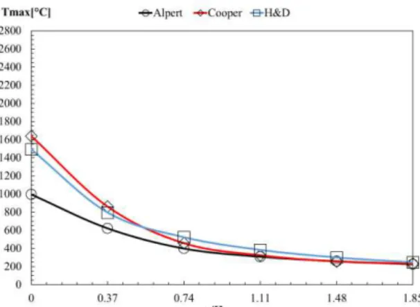
4.5- Comparison of results ... 39
4.5.1- Maximum temperature comparison for class 1 ... 39
4.5.2- Maximum temperature comparison for class 2 ... 40
4.5.3- Maximum temperature comparison for class 3 ... 40
4.5.4- Maximum temperature comparison for class 4,5 ... 41
4.5.5- Maximum velocity comparison for class 1 ... 41
4.5.6- Maximum velocity comparison for class 2 ... 42
4.5.7- Maximum velocity comparison for class 3 ... 43
4.5.8- Maximum velocity comparison for class 4,5 ... 43
5- CFAST model ... 45
5.2- The model ... 46
5.2.1- Simulation environment ... 46
5.2.2- Thermal properties ... 46
5.2.3- Compartments ... 47
5.2.4- Wall vents ... 48
5.2.5- Fires ... 48
5.2.6- Defining targets ... 48
5.2.7- Defining the fire detectors ... 48
5.2.8- Output results ... 49
5.3- Comparison of results ... 52
5.3.1- Maximum temperature comparison for all car classes ... 53
5.3.2- Maximum velocity comparison for all car classes ... 53
6- FLUENT model ... 55
6.1- Presentation of FLUENT ... 55
6.2- Equations to be solved ... 56
6.2.1- Continuity equation ... 56
6.2.2- Navier-stokes equation ... 56
6.2.3- Energy equation ... 57
6.2.4- Other equations ... 57
6.3- The model ... 58
6.3.1- Material models ... 59
6.3.2- Boundary conditions ... 60
6.4- Comparison of results ... 61
6.4.1- Temperature results from ANSYS fluent simulation ... 61
6.4.2- Velocity results from ANSYS fluent simulation ... 62
6.4.3- Maximum temperature comparison for all car classes ... 63
7- Conclusions ... 68
References ... 69
Annex 1: Results from correlative models ... 74
1- Alpert's results ... 74
2- Cooper's results ... 74
3- Heskestad and Delichatsios's results ... 74
4- Maximum temperature comparison between correlative models ... 75
5- Maximum temperature comparison between correlative models ... 76
Annex 2: Results from CFAST simulation ... 78
1- Positions of targets and heat alarm entering in CFAST simulation ... 78
2- Maximum temperature from CFAST numerical simulation ... 78
3- Maximum velocity from CFAST numerical simulation ... 78
4- Maximum temperature comparison between the correlations and CFAST ... 79
5- Maximum velocity comparison between the correlations and CFAST ... 80
Annex 3: Results from ANSYS fluent simulation ... 82
1- Material models ... 82
INDEX OF FIGURES
Figure 1.fire plume and ceiling jet [15]. ... 5
Figure 2.The three zones of the axisymmetric buoyant plume [5]. ... 7
Figure 3.Schematic of plume and ceiling jet flow for an unconfined ceiling I: Plume Region; II: Turning Region; III: Ceiling Jet Region [27]. ... 8
Figure 4.Modeled fires anchored on the burner setup corresponding to ˙Qc = (a) 1500, (b) 4500, and (c) 7500kW, illustrated with the instantaneous isocountour of stoichiometric mixture fraction. ... 11
Figure 5. Fire Scenarios [42]. ... 15
Figure 6. Schematic diagram for small localised fires [47]. ... 16
Figure 7. Energy release rate measured when burning 1.2 m by 1.2 m wood pallets, stacked to different heights [48] ... 18
Figure 8.HRR of different car classes. ... 19
Figure 9.Localized fire of our compartment. ... 23
Figure 10.Ceiling jet flow beneath an unconfined ceiling [54]. ... 28
Figure 11.The geometry of the compartment. ... 29
Figure 12.Temperature near the ceiling from Alpert correlations. ... 31
Figure 13.Velocity near the ceiling from Alpert correlations. ... 31
Figure 14.Tmax of all car classes calculated by Alpert correlations. ... 32
Figure 15.Vmax of all car classes calculated by Alpert correlations. ... 32
Figure 16.Temperature near the ceiling from Cooper correlations. ... 34
Figure 17.Velocity near the ceiling from Cooper correlations. ... 34
Figure 18.Tmax of all car classes calculated by Cooper correlations ... 35
Figure 19.Vmax of all car classes calculated by Cooper correlations ... 35
Figure 20.Temperature near the ceiling from Heskestad and Delichatsios correlations. ... 37
Figure 21.Velocity near the ceiling from Heskestad and Delichatsios correlations. ... 38
Figure 22.Tmax of car classes from Heskestad and Delichatsios correlations ... 38
Figure 23.Vmax of car classes from Heskestad and Delichatsios correlations ... 39
Figure 24.Comparison of the value of Tmax from the correlative models for class 1 ... 40
Figure 25.Comparison of the value of Tmax from the correlative models for class 2 ... 40
Figure 26.Comparison of the value of Tmax from the correlative models for class 3 ... 41
Figure 27.Comparison of the value of Tmax from the correlative models for class 4,5 ... 41
Figure 29.Comparison of the value of Vmax from the correlative models for class 2 ... 42
Figure 30.Comparison of the value of Vmac from the correlative models for class 3 ... 43
Figure 31.Comparison of the value of Vmax from the correlative models for class 4,5 ... 44
Figure 32.compartment in a two-zone model [43]. ... 45
Figure 33. Specific heat of concrete (left) and Thermal conductivity of concrete (right) [55].47 Figure 34. The geometry of our fire compartment. ... 48
Figure 35. Grid size of the compartment. ... 49
Figure 36.Results of temperature from CFAST simulation. ... 50
Figure 37.Results of velocity from CFAST simulation. ... 50
Figure 38.Results of Tmax from CFAST simulation. ... 51
Figure 39.CFAST simulation for Tmax. ... 51
Figure 40.Results of Vmax from CFAST simulation. ... 52
Figure 41.CFAST simulation for Vmax. ... 52
Figure 42.Comparison of Tmax for all car classes. ... 53
Figure 43.Comparison of Vmax for all car classes. ... 54
Figure 44.the Mesh of the model. ... 59
Figure 45.Properties of the air. ... 59
Figure 46.Boundary condition of the compartment. ... 60
Figure 47. Results of Tg from CFAST of all car classes. ... 61
Figure 48. Results of Vg from CFAST of all car classes. ... 61
Figure 49.Results of temperature from ANSYS fluent simulation of all car classes. ... 62
Figure 50.Results of velocity from ANSYS fluent simulation of all car classes. ... 63
Figure 51.Results of Tmax from ANSYS fluent simulation of all car classes. ... 64
Figure 52.Results of Vmax from ANSYS fluent simulation of all car classes. ... 65
Figure 53.Model and the grid size. ... 65
Figure 54.Results of Temperature when t=1500 s for all car classes. ... 66
INDEX OF TABLES
Table 1.Rough Measure of Energy Released or Generated from Various Sources [48]. ... 17
Table 2.HRR of different car classes. ... 19
Table 3.Thermal properties of Concrete and Steel. ... 22
Table 4.Tmax and Vmax getting form Alpert's correlations. ... 74
Table 5.Tmax and Vmax getting form Cooper's correlations. ... 74
Table 6. Tmax and Vmax getting form Heskestad and Delichatsios correlations. ... 75
Table 7.Comparison between correlative models for Tmax of class 1. ... 75
Table 8.Comparison between correlative models for Tmax of class 2. ... 75
Table 9.Comparison between correlative models for Tmax of class 3. ... 75
Table 10.Comparison between correlative models for Tmax of class 4,5. ... 76
Table 11.Comparison between correlative models for Vmax of class 1. ... 76
Table 12.Comparison between correlative models for Vmax of class 2. ... 76
Table 13.Comparison between correlative models for Vmax of class 3. ... 76
Table 14.- Comparison between correlative models for Vmax of class 4,5 ... 77
Table 15.Data of the six targets in the compartment. ... 78
Table 16.Data of the six heat alarms in compartment. ... 78
Table 17.results of CFAST simulation for maximum temperature. ... 78
Table 18.results of CFAST simulation for maximum temperature. ... 79
Table 19.Comparison of Tmax between correlative models and CFAST for class 1. ... 79
Table 20.Comparison of Tmax between correlative models and CFAST for class 2. ... 79
Table 21.Comparison of Tmax between correlative models and CFAST for class 3. ... 79
Table 22.Comparison of Tmax between correlative models and CFAST for class 4,5. ... 80
Table 23.Comparison of Vmax between correlative models and CFAST for class 1. ... 80
Table 24.Comparison of Vmax between correlative models and CFAST for class 2. ... 80
Table 25.Comparison of Vmax between correlative models and CFAST for class 3. ... 80
Table 26.Comparison of Vmax between correlative models and CFAST for class 4,5. ... 81
Table 27.Properties of concrete based on data points. ... 82
Table 28..Data of the target 7 in the compartment. ... 82
Table 29.Data of the heat alarm7 in the compartment. ... 82
NOTATION
NOMENCLATURE
Latin lower-case letters
ṁp Plume mass flow rate [kg/s]
r Radial distance from the fire [m]
t Time [min]
Latin upper-case letters
Cp Specific heat at constant pressure [kJ/ (kg K)]
D Diameter of fire source [m]
E Energy of combustion [MJ]
H Distance between the fire and the ceiling [m]
Hf Vertical distance between the floor and the ceiling [m]
H𝑠 Distance between the fire source of the car and the floor [m]
Kxx,yy,zz Thermal conductivity in x,y,z directions
Lf Flame height [m]
Lh Horizontal flame length [m]
QV Volumetric heat source
Q ̇ Total heat release rate (HRR) [kW]
Q̇c Convective part of the rate of heat release [kW], Q̇c= 0,8Q̇ by
default
Tmax Maximum temperature [°C]
T∞ Ambient temperature [°C]
V Velocity vector
Vmax Maximum velocity [m/s]
Vx;y;z Velocity in x, y, z directions
Z Height along the flame axis [m]
Z0 Virtual origin or height of virtual source above burning item [m]
Greek letters
𝛼 Convection [-]
𝛼𝑐 Coefficient of heat transfer by convection [W/m2 K]
𝜀 Emissivity [-]
𝜎 Stephan Boltzmann constant =5.67×10⁻⁸ [w/m2k4]
δ Thickness of ceiling jet [m]
λ Thermal conductivity [kW/ (m °C)]
ρ Density [kg/m3]
ρ∞ Ambient air density[kg/m3]
1- INTRODUCTION
One of the most important problems in fire protection is the rapid detection of fire in a room while the fire is sufficiently small to be easily controlled. Controllable fires generally exist for more than half a minute after ignition when flames are confined by inert barrier for air gaps to a distinct portion of the total available fuel.
Much of the work that is collected below deals with means to predict the temperature and velocities in the ceiling jet flow both above and remote from the fire source. In facilities with very high ceilings, the detectors could be closer to the ceiling than 1% of the ceiling-to-fire-source distance and will fall in the ceiling jet thermal and viscous boundary layers.
The velocity and temperature of the hot gases due the fire in compartment are two major dynamic characteristics that must be take in consideration in events of fire. The main goal of this work is to develop numerical simulations using two different software, which are CFAST (Consolidated Model of Fire and Smoke Transport), a calculation method based on the two zone models and CFD (Computational Fluid Dynamics), a finite volume based method. Also, simple calculation methods, based on the correlative models devoted to fire plumes and ceiling jets were used to compare results of temperature and velocity near the ceiling. The flow produced by the fire is considered unconfined with respect to the localized fire.
Five car classes were used to define different fire scenarios in open car parking that are to be analysed.
1.1- State of the art
In 1972, Alpert [1] presented Data on near maximum gas velocity and excess temperature in the ceiling jet induced by large scale fires that were used to obtain well-known ceiling jet formulas. These formulas have been re-examined in light of knowledge on the virtual plume origin and the convective component of the fire heat release rate. According to this research, fire detectors should be located in a vertical distance below the ceiling of no more than 6 % of the ceiling height.
growth rate. The local gas velocity in the hottest layer under flat ceilings can be related directly to the local temperature rise and ceiling clearance, regardless of time from ignition, fire-growth rate and, possibly, fire-growth behaviour.
In 1986 L. Y. Cooper and A. Woodhouse [3] studied the convective heat transfer from buoyant plume-driven ceiling jets to unconfined ceilings. The heat transfer was estimated using a formula for the temperature distribution below an adiabatic ceiling Tad (one obtained from
experimental data in the range 0 < r/H < 0.7 (r is the radial distance from the plume and H is the plume source-to-ceiling distance)). The new results were used to modify equations. The unconfined ceiling equations were used to estimate heat transfer to the confined ceilings of real compartment fire scenarios.
In 1987 L. Y. Cooper and D. W. Stroup [4] developed procedure to measure the thermal response of unconfined compartment, using an algorithm for convective heat transfer to the ceiling material from the fire-plume-driven ceiling jet. The results give an indication of the influence of convective heat transfer on peak ceiling thermal response, losses from fire plume gases, and radial variations and peak values of ceiling-to-floor irradiation during fires. The algorithm developed was used to predict the response of a variety of realistic ceiling constructions to different fire scenarios. In general, the results of the calculations presented were plausible, and they provide useful insight into the response of real ceilings to hazardous fires.
In 1989 Gunnar Heskestad & Michael A. Delichatsios [5] did a brief note to update correlations established previously by the authors for the ceiling flow generated by fires growing with the second power of time, based on knowledge of the actual heat of combustion of wood. The correlations were generalized to include combustibles with a significantly different convective fraction of total heat release rate than wood.An existing set of ceiling flow correlations for fires growing with the second power of time has been updated to reflect improved knowledge of the heat of combustion of wood. An additional set has been established based on convective heat release rate, useful for combustibles with different convective heat fractions than wood.
accessible database of fire data. Computer fire modelling is moving in a trend to provide predictions that are more accurate, as well as predictions about fire phenomenon that previously no computer fire model addressed.
In 1993 Leonard Y. Cooper [7] developed a research about the effect of the heat transfer on the location of the fire within a rectangular parallelepiped compartment. The model considered uniform ceiling temperatures, presenting an estimation of the convective heat transfer, due to ceiling-jet driven flows, to both the upper and lower parts of the walls. The model also presented the velocity and temperature distributions in the ceiling jet. The model equations were used to develop an algorithm and associated modular computer subroutine to carry out the indicated heat transfer calculations.The algorithm and subroutine are suitable for use in two-layer zone-type compartment fire model computer codes. CEILHT has been tested for a variety of instantaneous fire environments involving a 10 MW fire in an 8x8x4 m high enclosure.
In 2005, W. G. Weng and Y. Hasemi [8] presented a model to calculate the thermal response of an unconfined non-burning ceiling from an impinging buoyant diffusion flame. The model uses an algorithm that considers heat transfer into the ceiling. Also takes in to account the heat transfer due to radiation from the fire source to the ceiling surface, and from the ceiling surface to other materials. The predicted heat fluxes were compared with the existing experimental data, helping to validate the model.
In 2010 João Carlos Viegas [9] did a sensitivity analysis to study the interaction between the fire ceiling jet and the flow driven by jet fans, using CFD simulations, considering important parameters as position and intensity of fire source, transversal distance between jet fans, restriction of exhaust flow rate and dimension of car park exhaust opening. An analytical model for the flow field near the ceiling is developed and compared with CFD simulations.
In 2011 Ronald L. Alpert [11] revisited data on near-maximum gas velocity and excess temperature in the ceiling jet induced by large-scale fires that were used to obtain well-known ceiling-jet formulas published in 1972 have been re-examined in light of knowledge on the virtual plume origin and the convective component of the fire heat release rate. The new data correlations developed from this re-examination are compared with the original correlations that were based on actual ceiling height above the top fuel surface and actual fire heat release rate, instead of being based on ceiling height above the virtual origin and on the convective heat release rate. Such algebraic formulas are useful for predicting detection/activation times of ceiling mounted devices, e.g., fire sprinklers. To determine what mass flux of agent droplets from these activated sprinklers arrives at the fire source, it is shown that CFD coupled with droplet trajectory calculations have been used beginning in the mid-1980's to quantify the interaction between the fire induced plume/ceiling jet flow and droplet sprays.
In 2012 Yasushi Oka and Masaki Ando [12] developed a series of pool fire tests, using a flat unconfined ceiling and changing the ceiling inclination angle up to 40º. Two different fire heat release rates were used to simulate the effect of touching and not touching the ceiling, using steady-state conditions. The maximum temperature and its position were determined. The maximum velocity and its position were obtained by the particle image velocimetry method. These results were compared with the velocities obtained using a bi-directional flow probe. Empirical formulae for the temperature rise and velocity versus the radial distance from the plume impingement point along the steepest run in the upward direction were developed considering the effect of the inclination angle.
In 2013 Nils Johansson, Jonathan Wahlqvist and Patrick van Hees [13] did an evaluation of previously derived correlations for ceiling jet excess temperatures and velocities, after the development of 90 simulation in FDS. Authors also demonstrate how computer simulations could be used as a complement to actual fire experiments in fire science research. The evaluation indicates that the existing correlations will give a good estimate of the average temperature in a ceiling jet. However, it seems that the correlations will not give a good estimate of the maximum excess temperature or velocity. A new correlation to estimate the maximum temperature was developed.
predicted the ceiling jet temperature rise at the impingement point when the fire is located closely to the tunnel wall, but underestimated the normalized longitudinal distribution at a given location. The wall constraint effect on the normalized impingement ceiling jet temperature rise seemed independent of the heat release rate of the fire.
These experimental and mathematical modelling studies have provided the necessary understanding to predict some of the general transport behaviour in fires based on empirical correlations. The results of these investigations have advanced the understanding of fire phenomena and improved the design of fire protections systems. However, detailed measurements in well-controlled experiments are required for model development. In particular, characterizations of the velocity field in fire plume configurations are notably absent.
1.2- Plume and Ceiling jet fires
1.2.1- Ceiling jet fire
The ceiling jet is created when there is an impingement between a buoyant plume and flat unobstructed ceiling where the hot gases spreads radically under the ceiling, see Figure 1. Ceiling jet fire can also be defined as the rapid flow of gas in a surface layer below the ceiling surface that is driven by the buoyancy of hot combustion products.
1.2.1.1- Ceiling jet velocity
The ceiling jets in ordinary building enclosure fires have been investigated by Alpert [16] and Heskestad et al. [17]. However, the ceiling jets in tunnel fires, especially in longitudinally ventilated tunnel fires, is completely different with those in room fires. Hinkley [18] proposed an equation to estimate the gas velocity for small corridor fires, however, it is based on a simple assumption of constant Richardson number which is not suitable for the momentum dominant ceiling jet flows in tunnel fires. Li et al. [19] analysed the ceiling jet flows for small corridor fires. However, no entrainment was considered for the ceiling jets and the
Reynolds’ analogy was misused since in reality the convective heat flux rather than total heat flux should be used in the analogy.
1.2.1.2- Ceiling jet flow rate
Li et al. [20] proposed an equation to estimate the smoke flow rate at a certain height in a small fire under ventilation. This should be equivalent to the initial ceiling jet flow rate. However, the equation was only validated using the temperature data. Data of the initial ceiling gas flow rate are needed to validate this equation. Further, this equation could not be suitable for the strong flame plume.
1.2.1.3- Ceiling jet temperature
Li et al. [20, 21] have theoretically and experimentally investigated the maximum ceiling gas temperature and its corresponding position in tunnel fires and robust equations have been proposed for both low ventilation and high ventilation. However, how the flame temperature varies with distance in the vicinity of the fire has not yet been fully explored. Ingason and Li [22] found that while correlating all the temperature distribution curve, there is
a “virtual origin” along the ceiling. The horizontal distance at the ceiling between the fire source
and virtual origin needs to be clearly determined.
Ingason et al. [23] investigated the radiation from the ceiling flame to the tunnel structure in the Runehemar tunnel fire tests. Ingason and Li [24] also found that there is a strong correlation between the ceiling gas temperature and the heat flux at the floor level in the far-field of the fire. However, the radiation directly from the flame to the objects at floor level or at a certain height in the vicinity of the fire needs to be thoroughly investigated, since the fire spread to the neighboring objects or vehicles mainly results from this radiation.
1.2.2- Plume fire
The fire plume is usually divided into three regions: ‘persistent flame’ zone at the flame
base, ‘intermittent flame’ zone following, and ‘buoyant plume’ in the highest region see Figure 2. The persistent zone has chemical reactions and air entrainment taking place and thus is the most interesting regarding flame establishment, stabilization, and mass formation. In this first zone, where the chemical reactions and heat release occur, the flame appears nearly laminar with a light blue colour. The heat release induces a large increase in the gas velocity and temperature in this region. The characteristics of flame in this zone is generated by the following basic mechanism as heat transfer, radiative and convective. In the intermittent zone, the flame turns into yellow colour with the temperature maximum shifting toward the burner axis. Air
entrainment in these two zones pushes the flame inward, forming a characteristic ‘neck’ at the
top of which intermittent, large eddy structures are formed, see Figure 3. In the plume zone, velocities and temperatures decrease with height [25].
The unconfined point-source plume configuration has been used by previous researchers to establish plume theory. This theory provides solutions for the temperature profile, velocity profile and entrainment for thermal plumes at various elevations above the source [15] . Based on point source theory, the behaviour of the fire plume is independent of the details of the heat source including the fuel source and source geometry. The turbulent flowabove a point source of heat is analysed in terms of the total mass, momentum and energy integrated across the plume cross section assuming that the entrainment velocity is proportional to the centreline plume velocity. Assuming the average temperature and velocity across the plume have Gaussian profiles, Zukosiki et al. [26] provides a theoretical solution for the plume momentum and energy equations by using an integral method.
Figure 3.Schematic of plume and ceiling jet flow for an unconfined ceiling I: Plume Region; II: Turning Region; III: Ceiling Jet Region [27].
The virtual origin Zo [m] of the axis is given by Eq 1:
5 2
0 1.02D 0.00524Q
Z Eq 1
viscous interactions with ceiling, there is a competition between turbulent mixing and stable stratification along the ceiling. A number of theoretical and experimental fire studies were performed in the impinging plume configuration. Most notably, Alpert [27] performed an analytical and experimental study developing the theory and associated scaling laws for fire induced ceiling jets. His analysis successfully predicted the maximum temperature distributions in the ceiling jets and is widely used in hazard analysis. Based on his analysis, he provided relationships for dimensionless ceiling layer thickness, velocity, and temperature, which compares favourably with measurements. In fact, his analysis revealed that these flow quantities are relatively insensitive to geometric scale. Alpert suggested that credible small-scale fire experiments could be conducted at ceiling heights down to 0.6 m.
Motevalli and Marks [28]conducted small-scale experiments of ceiling jet heat transfer, which generally compared favourably with other ceiling jet data and analysis for x1/H < 2. The
velocity and temperature measurements were obtained for unconfined ceiling jets under ceiling transient and steady-state conditions. Small fires of 0.5 kW to 2.0 kW were produced with a premixed methane-air burner. These measurements represented one of the most detailed studies of unconfined ceiling jets and were in general agreement with large scale data. Noticeable discrepancies were encountered when comparing measured momentum and thermal thickness between investigations. These discrepancies were attributed to coarse measurements and simplifying assumptions by other investigators concerning the equivalency of the momentum and thermal thicknesses in other analyses. However, no convective heat transfer rate to the ceiling was studied in that investigation.
Convective heat transfer from the ceiling jet layer to the ceiling surface has beenstudied by Veldman et al. [29]. They conducted experiments to investigate the axisymmetric heat transfer from small scale fires (1.17 kW and 1.53 kW) under the impinging plume condition. An empirical correlation involving the source strength, Q, and ceiling height, H, was found to correlate measurements of the adiabatic wall temperature and its radial variation in the range from 0 ≤ x1/H ≤ 0.7. A similar correlation for estimating the ceiling heat transfer coefficient
was confirmed by the experimental results. However, their study was limited by the absence of velocity measurements in both plume and ceiling jet configurations. You and Faeth [30] also conducted a study on heat transfer from an impinging fire plume to a horizontal ceiling. Their measurements were compared with predictions of both differential and integral models where x1/H < 1.7. The integral model provided a reasonable prediction of flow properties and ceiling
influenced by entrainment. Ceiling friction has only had a secondary effect on the flow structure predictions.
Cooper [31, 32, 33] developed a heat transfer analysis by using an adiabatic ceiling surface temperature, Tad, as the reference temperature in Newton’s law of cooling. The adiabatic
surface temperature, Tad, depends on the fire configuration, but is independent of the ceiling
surface temperature. This adiabatic surface temperature describes the gas temperature decay along the ceiling due to entrainment.
Cooper provided correlations for Tad distributions along the ceiling by analysing
previous researcher’s experimental data [29, 34]. Correlations of the heat transfer coefficient, h, in the turning region and the ceiling jet region of the plume are also provided. Convective heat transfer from the ceiling jet to the ceiling surface has been estimated using correlations of Tad and h in the range of 0 ≤ x1/H ≤ 2.2.
Goldstein et al. [35] also investigated the convective heat transfer of a heated circular air jet impinging on a flat surface using Tad as a reference temperature. The concept of
effectiveness has been adopted to express the adiabatic surface temperature in dimensionless form. The heat transfer coefficient was also found to be independent of the relative magnitude of the jet temperature and the ambient temperature, if the adiabatic wall temperature is used as a reference temperature in the definition of the heat transfer coefficient. In the current research, the concept of effectiveness is applied with modification to the analysis of the convective heat transfer rate from the ceiling jet to the ceiling.
1.2.2.1- Fire Plume Characterization
experimental burner setup involves spray flames that produce jet flames of high momentum. Higher velocities are required in the simulations applying buoyant diffusion flames of propane, which do not provide sufficient momentum to the resulting plumes as compared to the spray flames. Similar to previous studies [36], by adjusting the air inlet velocities a reasonably accurate match with experimental results was obtained. As a reference case, results from the
simulation of the ˙Qc=1500kW plume with the volumetric fire source. The volumetric plume source, not surprisingly, produces good comparisons and the computed temperature distribution matches the experimental data and its slope compares well with the correlation between 2.5 and 6 m; velocities are slightly over-predicted compared to the correlation values, however they fall within the experimental uncertainty. Figure 4 also shows the predicted centreline excess temperature and velocity using the burner setup, compared against experimental data and correlations [37] for Qc=1500kW. Here, it should be mentioned that plume centreline temperatures from the thermocouples were corrected for radiation loss by equating convective heat transfer (calculated with the application of a Nusselt number correlation) from the hot gases to the thermocouple bead to the radiation loss from the bead to the ambient. An optimum condition with inlet air velocity of 10 m/s was determined with emphasis given to the temperature profile as relative thermal index (RTI) is strongly affected by temperature variation as compared to velocity on which there is a square root dependence.
(a) (b) (c)
Figure 4.Modeled fires anchored on the burner setup corresponding to ˙Qc = (a) 1500, (b) 4500, and (c) 7500kW, illustrated with the instantaneous isocountour of stoichiometric mixture fraction.
Limited research has been carried out on the flame length in a large tunnel fire. Rew and Deaves [38] presented a flame length model for tunnel fires, which included heat release rate and longitudinal velocity. However, neither tunnel width nor tunnel height was considered. Their research was based on the investigation of the Channel Tunnel Fire in 1996 and test data from the HGV-EUREKA 499 fire test [39] and the Memorial Tests [39]. The equation is a conservative fit to a limited data obtained from the HGV-EUREKA 499 test. The weakness of the proposed equation is that no geometrical parameter has been taken into account, which makes it impossible to predict the flame length for other tunnels with different geometries. Lönnermark and Ingason [40] investigated the flame lengths from the Runehamar tests and used Alpert’s equation [16] for ceiling jet temperatures to estimate the form of equation for flame length, and determined the uncertain coefficients by regression analysis. However, the tunnel ceiling is confined and thus the equation proposed by Alpert [16] may not be appropriate for large tunnel fires. Ingason and Li [22] presented a dimensionless equation to estimate the flame lengths under high ventilation. However, the flame lengths under low ventilation have not yet been investigated. Moreover, a theory needs to be proposed to clarify the correlation between ceiling flame combustion and flame length.
1.2.3- Fire spread
1.3- Plan of thesis
In chapter 1, the definition of jet fire is explained; the state of the art is presented and the plan of the thesis is summarised.
In chapter 2, the definition of fire scenarios using a localized fire for the event of a car fire is presented. Different car classes burning events are presented with the results of the Heat Release rate (HRR).
Chapter 3 provides a general definition of heat transfer with discussion of the different modes of heat transfer which are included in the fire events.
Chapter 4 presents different correlative models (Alpert, Cooper, Heskestad and Delichatsios) to estimate the maximum temperature and velocity near the ceiling. The results are compared for different fire events and one fire compartment.
Chapter 5 is dedicated to the numerical simulation using CFAST software. A brief definition of CFAST will be presented followed by a discussion of the results about the maximum temperature and velocity obtained near the ceiling, between this simulation and results from the correlative models.
Chapter 6 is dedicated to the field analysis using computational fluid dynamics, where different fire events are going to be simulated, based on specific solution for equations.
2- FIRE SCENARIO
The fire scenario (position of the vehicles) should represent the most unfavourable
situation for the elements (or substructure). The vehicles’ type mostly used in fire scenarios are
cars, classified according their calorific potential or combustion energy (E). Five different car classes were defined: class 1-E=6000 MJ (ex. Peugeot 106); class 2-E=7500 MJ (ex. Peugeot 306); class 3-E=9500 MJ (ex. Peugeot 406), and classes 4 and 5-E=12 000 MJ (ex. Peugeot 605 or 806) [42].
According to statistical studies of actual fires in car parks, 90% of the vehicles involved in a fire are classified as class 1, 2 or 3. The INERIS-Institut National de l'Environnement Industriel et des Risques, considers that fire scenarios with cars of class 3 should be used to evaluate the structural stability of the car park under fire, and the fire resistance of the structure should be ensured during the entire fire scenario, or at least, if allowed by National requirements, up to a certain resistance time R of the elements defined as for the ISO curve. In addition, a scenario including a commercial vehicle (van containing 250 kg of highly flammable material: E=19 500 MJ) corresponds to an extreme situation and should only be used to check the global behaviour of the structure, assuming local collapse, without progressive collapse [42].
Five fire scenarios recommended or already used for the study of fires in car parks are presented and described. ECCS indicates that one or two vehicles in fire correspond to the most critical scenario in an open car park. One car burning at mid-span under the beam (corresponding to the maximum bending moment position) is defined as scenario 1. The scenario 2 involves two burning cars, one on each side of the column; this fire event was considered being the most dangerous for the columns. INERIS defines three additional fire scenarios: i) scenario 1 of ECCS, but with a commercial vehicle under the beam, ii) scenario 3 - involving seven class 3-cars, with possibility of a commercial vehicle in places 0 or 1a (Figure 5), iii) scenario 4 - involving four class 3-cars parked face to face, with possibly a commercial vehicle in places 0, 1a, 1b or 2 [42].
Figure 5. Fire Scenarios [42].
2.1- Localized fires
Depending on the height of the fire flame, relative to the ceiling of the compartment, a localised fire can be defined as either a small fire (or open-air fire) or a large fire impacting on the ceiling. For a small fire, a design formula is given to calculate the temperature in the flame along the vertical axis. For a bigger fire, some simple steps have been developed to calculate the heat flux received by the surfaces exposed to the fire at the ceiling level. The limitations of this approach include: (i) the diameter (D) of fire: D≤10 m, and (ii) the heat release rate (Q) of
the fire: Q≤50 MW [43].
In a localized fire, there is an accumulation of combustion products in a layer beneath the ceiling (upper layer), with a horizontal interface between this hot layer and the lower layer where the temperature of the gases remains much colder. This situation is well represented by a two-zone model, useful for all pre-flashover conditions. Besides calculating the evolution of gas temperature, these models are used in order to know the smoke propagation in buildings and to estimate the life safety as a function of smoke layer height, toxic gases concentration, radiative flux and optical density. The thermal action on horizontal elements located above the fire also depends on their distance from the fire. It can be assessed by specific models for the
evaluation of the local effect on adjacent elements, such as Heskestad’s or Hasemi’s method
[43].
In a localised fire, as shown in Figure 6, the highest temperature is at the axis of the vertical flame, decreasing towards the edge of the flame. The flame axis temperature changes with height. It is roughly constant in the continuous flame region and represents the mean flame temperature. The temperature decreases sharply above the flames as an increasing amount of fresh air enters into the fire compartment [44]. EN 1991-1-2 [45] provides a design formula to calculate the temperature in the plume of a small localised fire, based on the fire model developed by Heskestad [46]. It can be applied to open-air fires as well. Considering a localised fire as shown in Figure 6, the flame height Lf of the fire is provided by:
5 2 0148 . 0 02 .
1 D Q
Lf Eq 2
Where D is the diameter of the fire (m); Q is the heat release rate of the fire (W). This model allows determining the temperatures along the vertical axis of the flame. However, in a real structural scenario, a column and respective flame are likely to be positioned side by side. Therefore, the temperature estimated by the first model is unlikely to be the boundary temperature of a column subjected to a localised fire. In order to use this fire model, a configuration factor is needed to estimate the radiative heat flux from the flame to the steel column. Moreover, an estimation of gas temperatures in the vicinity of the column is a prerequisite to assessing the convective heat flux. For these reasons, the heat flux from a localised fire to a steel column cannot be estimated using Eurocode procedures [47].
2.1.2- Large fires impacting on the ceiling
When a localised fire becomes large enough, with Lf ≥ H, the fire’s flames will impact on the ceiling of the compartment. The ceiling surface will cause the flame to turn and move horizontally beneath the ceiling. EN 1991-1-2 [45] presents a design formulation to calculate temperatures in a ceiling slab and in the beams, that may support the slab. This model is based on the experimental works performed by Hasemi to calculate the location of the virtual heat source. Figure 7 shows a schematic diagram of a localised fire impacting on the ceiling with the ceiling jet flowing beneath [47].
2.2- Definition of fire (HRR) fire event
Energy release rate (often termed heat release rate or HRR) is measured in W, kW, or MW. Table 1 gives some characteristic values of energy released by various burning fuel packages and heat output from different sources.
Table 1.Rough Measure of Energy Released or Generated from Various Sources [48].
Heat source Power
A burning cigarette 5 W
A typical light bulb 60 W
A human being at normal exertion. 100 W
A burning wastepaper basket. 100 kW
A burning 1m2 pool of gasoline. 2.5 MW
Burning wood pallets, stacked to the height of 3 m. 7 MW Burning polystyrene jars, in cartons, 2 m, 4.9 m high. 30–40 MW Output from a typical reactor at a Nuclear Power Plant. 500–1000 MW
Figure 7. Energy release rate measured when burning 1.2 m by 1.2 m wood pallets, stacked to different heights
[48]
The rise of the rate of heat release to the maximum value (see Figure 7, Figure 8) may be given by the Eq 3 or by other specific equation, where the HRR represents the Heat Release Rate of the fire during the growth phase [MW], t represents the time [s] and ta represents time
constant.
2/ta t
HRR Eq 3
There are basically two approaches available when determining the design fire for a given scenario. One is based on knowledge of the amount and type of combustible materials in the compartment of fire origin. The other is based on knowledge of the type of occupancy, where very little is known about the details of the fire load. In the first case, an object is assumed to ignite and start to burn. The resulting energy release rate vs. time can in many cases be estimated using data from previous experiments where energy release rate has been measured. However, in many design situations there is very little information available on the combustible content of the room of fire origin. In this case, knowledge of the type of occupancy, any available statistics, and engineering judgment must be used to arrive at a design fire load.
Table 2.HRR of different car classes.
Time Time Class 1 Class 2 Class 3 Class 4 Class 5 Min Sec HRR [kW] HRR [kW] HRR[kW] HRR[kW] HRR[kW]
0 0 0 0 0 0 0
4 240 884 1105 1400 1768 1768
16 960 884 1105 1400 1768 1768
24 1440 3474 4342 5500 6947 6947
25 1500 5242 6553 8300 10484 10484
27 1620 2842 3553 4500 5684 5684
38 2280 632 789 1000 1263 1263
70 4200 0 0 0 0 0
As can be seen from the results of cars burning tests, both car class 4 and 5 have the same values of HRR. The heat release rate curves of the different car classes for the new generations is depicted Figure 8 and shows a comparison between these curves. During any, time dependent fire, such as a class 3 vehicle, the energy release rate (HRR) increases from zero to a maximum value for time equal to 25 minutes and decreases to zero at the end of the event.
Figure 8.HRR of different car classes.
2.2.1- Factors controlling energy release rates in enclosure fires
The energy release rate will vary with time. Figure 7shows a schematic graph of the energy release rate vs. time measured when wood pallet stacks of different heights burn. Such
measurements are often termed “free burn” tests, indicating that the items are burning without
any effects of the enclosure in which the fire takes place [48].
2.2.1.1- Enclosure effects
When an item burns inside an enclosure, two factors mainly influence the energy released and the burning rate. First, the hot gases will be collected at the ceiling level and heat the ceiling and the walls. These surfaces and the hot gas layer will radiate heat toward the fuel surface, thus enhancing the burning rate. Second, the enclosure vents (doors, windows, leakage areas) may restrict the availability of oxygen needed for combustion. This causes a decrease in the amount of fuel burnt, leading to a decrease in energy release rate and an increase in the concentration of unburnt gases.
If, however, the opening is relatively small, the limited availability of oxygen will cause incomplete combustion, resulting in a decrease in energy release rate, which in turn causes lower gas temperatures and less heat transfer to the fuel. The fuel will continue to release volatile gases at a similar or somewhat lower rate. Only a part of the gases combusts, releasing energy, and unburnt gases will be collected at ceiling level. The unburnt gases can release energy when flowing out through an opening and mixing with oxygen, causing flames to appear at the opening.
In summary, compartment heat transfer can increase the mass loss rate of the fuel, while compartment vitiation of the available air near the floor will decrease the mass loss rate [48].
2.2.2- Energy release rates based on free burn measurements
techniques, discuss methods for calculating energy release rate from pool fires, and show experimentally determined energy release rate curves for various residential and industrial items [48].
2.3- Definition of fire compartment
Space within a building, extending over one or several floors, which is enclosed by separating elements such that fire spread beyond the compartment is prevented during the relevant fire exposure. Fire compartment is a volume within a building which is completely surrounded with fire-resistant construction elements, which can be integrated right into the structure of the building. Fire compartments are not absolutely fire proof. Fire can work its way into or out of a fire compartment if it is intense enough, poorly managed, or not addressed quickly enough. Existing buildings can be retrofitted to create fire compartments.
Movable barriers can be installed, or people can remodel parts of a building to create a fire compartment. Also known as a fire zone, a fire compartment can also sometimes address the potential of flood damage, as the same materials which keep fire out can sometimes keep water at bay as well. The fire compartments can consist of rooms or groups of rooms. When a fire starts inside a compartment, the sealed nature of the area can be partitioning the fire, preventing it from spreading to other areas. The fire compartment used in this study represents a fire in open car park, being the dimensions defined in the next sections [49].
2.3.1- Phases of fires in compartment
The fire in compartment is characterized by four principal phases. The first phase is the fire development which is the evolution of the size of the fire from a small incipient fire. If there is no action to stop the fire, it will have the maximum size. In this situation, the fire size will be controlled by the amount of existing fuel or by the amount of ventilation.
emission of radiation, being primarily directed downward, higher and higher. This radiation focuses on the existing objects in the compartment is partially absorbed and increases the temperature of these objects, which continue to produce volatile combustibles. When the upper layer reaches of 600°C order, the incident radiation is sufficient to ignite these released volatile combustibles, bringing simultaneously all objects under fire. This incident radiation has an estimation value of 20 kW/m2 at ground level [50].
The third phase corresponds to the full development of the fire, which is affected by: a) the size and shape of the enclosure, b) the amount, distribution and type of fuel in the enclosure, c) the amount, distribution and form of ventilation of the enclosure and d) the form and type of construction materials comprising the roof (or ceiling), walls and floor of the enclosure.
The fourth phase corresponds to the cool down of the fire, and depends on the fire brigade intervention or the limitation on fuel or oxygen.
2.3.2- Characteristics of the fire compartment
The compartment in this study is named open car parking and has the following geometry characteristics: 10m width, 10m depth, and height= 3m. It is characterized by the existence of concrete slabs. The compartment consists in two major walls, one ceiling and one floor. The heat flows through the ceiling, walls, and floor of a compartment. Two zones are expected to define the fire compartment, which are the lower layer zone and upper layer zone. The thermal properties of concrete and steel are presented in Table 3. Steel was considered to define the target material and concrete was considered to define the material of the slab. Two zones are expected to define the fire compartment, which are the lower layer zone and upper layer zone. The compartment has also two major wall vents (open lateral walls), with 0m for sill, 3m for soffit and 10m width [51], seeFigure 9.
Table 3.Thermal properties of Concrete and Steel.
THERMAL PROPERTIES CONCRETE STEEL
Density 2200 kg/m3 7850 kg/m3
Thermal conductivity 0.002 kW/(m °C) 0.053 kW/(m ° C) Specific heat 0.9 kJ/(kg °C) 0.425 kJ/(kg °C)
Figure 9.Localized fire of our compartment.
2.4- Definition of different fire events
A "fire event" shall be defined as an occurrence in which extinguishing media was used to suppress fire. This may mean a portable fire extinguisher, water from fire department efforts, the activation of a kitchen vent hood, a building's sprinkler system, or any other fire suppression system within a building. On the rare occasion when evidence of fire is present, and the fire has self-extinguished, this will also be identified as a fire event. In this study, the fire even of a burning car was considered.
Many tests were done in previous years to calculate the heat release rate from car fire events. The first tests carried out in opened conditions were developed by Mangs and Keski-Rahkonenin the 90’s [42].Ten tests of burning cars were done between 1995 and 1996, involving 15 cars old series (70ies/80ies) and a new generation series (90ies). For cars class 3, with the performance of one car in five tests and two cars in the other five tests. The graph of the comparison between the HRR of the two-generation showed that the energy released by a
car made in 1995 was twice that of a 1980’s car. Some of the HRR results [49].
2.5- Fire detection
fuel and impinge upon the ceiling. The ceiling surface causes the flow to turn and move horizontally beneath the ceiling to other areas of the building located at some distance from the fire. The response of detection devices (heat/smoke detectors) and sprinklers installed below the ceiling submerged in this hot flow of combustion products provides the basis for the building’s active fire protection measures.
Smoke and heat detectors are best suited for fire detection in confined spaces, where rapid heat generation can be expected in the event of a fire. Smoke and heat detectors have been installed extensively in most nuclear power plants. Generally, such detectors are installed as part of a building-wide alarm system, which typically alarms in the main control room. The purpose of such systems is to provide early warning to building occupants, and rapid notification of the fire brigade. Some detection devices will also perform the function of automatically actuating suppression systems and interfacing with other building systems such as heating, ventilation, and air-conditioning (HVAC).
Detection is critical to fire safety in nuclear power plants since a potential fire hazard may involve safe plant shutdown. Consequently, safety-related systems must be protected before redundant safety related systems become damaged by the fire.
3- HEAT TRANSFER
There are three mechanisms by which heat is transferred from one object to another: radiation, convection, and conduction. Classical textbooks on heat transfer provide innumerable hand-calculation expressions for calculating heat fluxes to and from solids, liquids, and gases, as well as expressions for estimating the resulting temperature profiles in a target. These analytical expressions are usually arrived at by setting up the energy balance, by assuming constant properties and homogeneity in the media involved, and by ignoring the heat transfer mechanisms that seem to be of least importance in each case. The radiative heat flux from flames, hot gases, and heated surfaces impinging on a solid surface can be estimated using classical heat transfer and view factors. The same applies for convective heat transfer to solids and conductive heat transfer through solids. The surface temperature of a solid subjected to a radiative, convective, or conductive heat flux can be calculated by hand assuming the solid is either semi-infinite or behaves as a thermally thin material. Numerous types of heat transfer problems can be solved in this way. Assuming that a secondary fuel package is subjected to a known heat flux and that it has a certain ignition temperature and constant thermal properties, then the time to ignition can be calculated. Similarly, if the activation temperature of a sprinkler bulb is known, the activation time can be estimated. Several other problems can be addressed in this way, including temperature profiles in building elements, flame spread over flat solids, heat detector activation, spread of fire from one building to another, etc. Analytical solutions to such problems can be found in standard textbooks on heat transfer [48].
3.1- Conduction
Conduction is at transfer through solids or stationery fluids. When someone touch a hot object, the heat that this person feel is transferred through the skin by conduction. Two mechanisms explain how heat is transferred by conduction: lattice vibration and particle collision. Conduction through solids occurs by a combination of the two mechanisms; heat is conducted through stationery fluids primarily by molecular collisions.
In fluids, conduction occurs through collisions between freely moving molecules. The mechanism is identical to the electron collisions in metals. The effectiveness by which heat is transferred through a material is measured by the thermal conductivity, k. A good conductor, such as copper, has a high conductivity; a poor conductor, or an insulator, has a low conductivity) [43].
3.2- Convection
Convection uses the motion of fluids to transfer heat. In a typical convective heat transfer, a hot surface heats the surrounding fluid, which is then carried away by fluid motion. The warm fluid is replaced by cooler fluid, which can draw more heat away from the surface. Since the heated fluid is constantly replaced by cooler fluid, the rate of heat transfer is enhanced. Natural convection (or free convection) refers to a case where the fluid movement is created by the warm fluid itself. The density of fluid decrease as it is heated; thus, hot fluids are lighter than cool fluids. Warm fluid surrounding a hot object rises, and is replaced by cooler fluid. The result is a circulation of air above the warm surface
Forced convection uses external means of producing fluid movement. Forced convection is what makes a windy, winter day feel much colder than a calm day with same temperature. The heat loss from your body is increased due to the constant replenishment of cold air by the wind. Natural wind and fans are the two most common sources of forced convection [43].
3.3- Radiation
Radiative heat transfer does not require a medium to pass through; thus, it is the only form of heat transfer present in vacuum. It uses electromagnetic radiation (photons), which travels at the speed of light and is emitted by any matter with temperature above 0 Kelvin (-273 °C). Radiative heat transfer occurs when the emitted radiation strikes another body and is absorbed.
~10-7 m contain less energy and therefore have little effect on life. A second characteristic, which will become important later is that radiation with longer wavelengths generally can penetrate through thicker solids. Visible light is blocked by a wall. However, radio waves, having wavelengths on the order of meters, can readily pass through concrete walls.
4- CORRELATIVE MODELS
4.1- Definition of correlative models
Correlations to estimate temperatures and velocities in the hot gases beneath a ceiling in a fire, a so-called ceiling jet, have existed for at least four decades. These types of correlations are often used in fire safety engineering in order to get an estimate of sprinkler and/or heat detector activation in enclosure fires. Such correlations can also be used to estimate damage if a ceiling material will ignite or if structures will be affected. A ceiling jet is created when a buoyancy driven plume impinges on a flat un-obstructed ceiling and the hot gases spreads radially under the ceiling, see Figure 10. As the ceiling jet moves radially from the outward, air will be entrained and the temperature cools down due to entrainment of cold air and heat losses to the ceiling. If the ceiling jet is unconfined it will have a maximum thickness of about 5-13% of the total room height and the maximum temperature will be at a distance of 1% of the room height below the ceiling. The thickness of the ceiling jet has been defined as the distance to where the excess of gas temperature drops to 1/e of (1/2.72) the maximum excess temperature. In a normal compartment fire, this type of unconfined ceiling jet will only exist in the earliest stages of fire development before the hot gases will accumulate in the compartment. The correlations have also been implemented in computer software, like DETACT-QS and CFAST, and used as a part of the traveling fires concept. Presently, there is a range of ceiling jet correlations available for different applications, e.g. for transient fires and confined ceilings [53].
The main parameters of the fire induce ceiling jet are represented. For this case, it is assumed that this fire is equivalent to a pool fire with a diameter D=2 m, an elevation surface Hs equivalent to 0.3 m above the ground and a remaining distance H up to the ceiling equals 2.7 m, see Figure 11.
Figure 11.The geometry of the compartment.
4.2- Alpert correlations
Alpert assumed an axisymmetric fire induced flow beneath a flat, horizontal ceiling that was unobstructed by walls 1 and the ceiling jet was divided into two regions. Thus there are two sets of correlations, for the maximum excess temperature (t max) and maximum velocity (u max), presented. The first one is valid in the turning region where the plume impinges the ceiling
(r/H≤0.18 for equation 3 and r/H≤0.15 for equation 5) and is independent of the radial distance of the plume. The second set of correlations is valid in the far field (r/H>0.18 for equation 2 and r/H>0.15 for equation 4) and is dependent on the radial distance from the plume centreline. The correlations developed by Alpert for determining maximum ceiling jet temperatures and velocities in S.1. Units are:
r/H> 0,18 H T T 3 2 ) r Q ( 38 , 5 max
Eq 4
r/H≤0,18
3 5
.
3 2
max 16,9
H Q T
r/H> 0.15 6 5 . 2 1 3 1 197 , 0 max r H Q
V Eq 6
r/H≤0,15 Vmax0,96(Q/H)13 Eq 7
Where H is the ceiling height, r is the radial distance from the plume centreline and Q
is the heat release rate of the fire. These original correlations where found with the help of qualitative curve fit of experimental data. A range of different types of fuels was used in the experiments but no regard was taken to the size of the convective part of the heat release rate, which later has been showed to control the properties of fire plumes. Alpert also conducted a numerical study of ceiling jets. It was, among other things, studied how heat transfer to the ceiling affects the ceiling jet and it was seen that there was no large effect on the ceiling jet temperature and thickness within a radial distance of less than 1 ceiling height (r/H<1). However, at distances of 3 to 5 ceiling heights, the effects were significant [53].
These correlations are divided into two zones, one part applies to the region of impingement where the upward flow of gas in the plume turns to flow out beneath the ceiling horizontally. The correlations are based on measurements collected during test burns of fuel arrays of wood and plastic pallets, cardboard boxes, plastic materials in cardboard boxes, and liquid fuels with energy release rates ranging from 668 kW to 98 MW under ceiling heights from 4.6 to 15.5 m.
4.2.1- Maximum Velocity and Temperature during the fire event
Class 1 Class 2
Class 3 Class 4,5
Figure 12.Temperature near the ceiling from Alpert correlations.
Class 1 Class 2
Class 3 Class 4,5
4.2.2- Maximum Temperature and Velocity for different ratio r/H
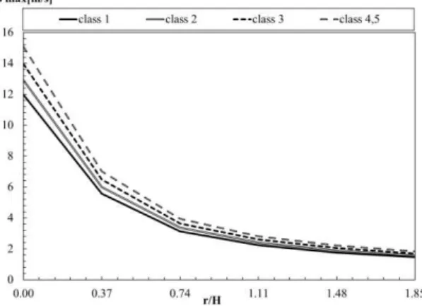
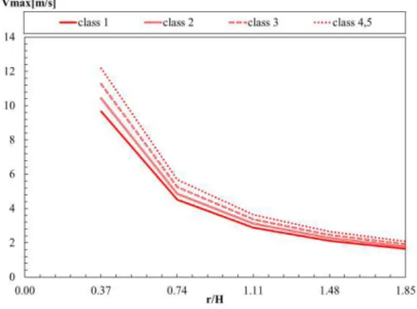
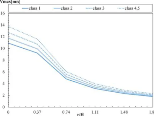
From the results of the velocity and temperature in the hot zone layer, calculated by the correlations developed by Alpert, the maximum dynamic characteristics were extracted from the event for a time equal to 25 minutes (1500s). The maximum velocity and temperature curves are represented respectively in Figure 14 and Figure 15 against r / H in different positions for classes 1, 2, 3 and 4 5.
Figure 14.Tmax of all car classes calculated by Alpert correlations.
Figure 15.Vmax of all car classes calculated by Alpert correlations.

![Table 1.Rough Measure of Energy Released or Generated from Various Sources [48].](https://thumb-eu.123doks.com/thumbv2/123dok_br/16815114.751098/37.892.163.727.636.829/table-rough-measure-energy-released-generated-various-sources.webp)